
Abstract
A numerical-analytical approach was utilized to construct a predictive model of cutting force for machining unidirectional carbon fiber reinforced polymer (UD-CFRP) laminates. The force coefficients in the model, which include friction angle, shear plane angle, shear strength, and rebound height, can be characterized by the fiber orientations ranging from 0° to 180°. The accuracy of the model was confirmed through experimental verification. The results indicate good agreement between the predicted and experimental values, with relative errors below 14.8%, except for the thrust force at 90°. Additionally, the study examined the influence of rake angle and flank angle on the cutting force, revealing two critical points in the predicted cutting force curve throughout the fiber orientation. These turning points shifted with changes in the rake angle. For instance, the value of the first critical point changes from 60° to 45° when the rake angle range shifts from [0°, 5°] to [10°, 15°]. This indicates that a larger rake angle facilitated an earlier transformation of chip formation mode, leading to a decrease in cutting force. Furthermore, the cutting force decreased as the rake angle increased between the two turning points. The impact of the flank angle on the cutting force was determined to be minimal, and the turning points’ positions remained consistent as the flank angle increased.
Keywords
Introduction
Carbon fiber reinforced polymer (CFRP) composites are widely used in the aerospace industry as primary structural components because of their superior properties. While CFRP parts are often fabricated to near-net shape, post-machining is necessary to ensure that the components meet assembly requirements. The material removal mechanism of CFRP is different from that of metal due to its anisotropy and non-homogeneity, which is largely influenced by the fiber orientation angle.1–3 Many scholars have made substantial efforts to understand the material removal mechanism in CFRP machining, including studying chip formation, visualizing machining damage, and predicting cutting force using models.4–6
Numerous studies have been conducted to explore the cutting process of unidirectional CFRP (UD-CFRP) using finite element methods and analytical modeling. Three main finite element cutting models have been proposed to investigate the variation of cutting force and material failure mode, i.e., the microscopic model,7–9 macroscopic model,10–12 and macro-micro model.13–15 These models have shown acceptable predictions of the principal cutting force, but the thrust force still needs improvement. Additionally, responses such as temperature distribution, delamination, surface defects, and subsurface damage have been investigated at various fiber orientations. Analytical methods have also been used to develop the quantitative relationship between the cutting forces and the process parameters in orthogonal cutting of UD-CFRP, including macro-mechanical and micro-mechanical models.16–18 These existing analytical models focus on force prediction by pre-defining the chip formation modes from experimental observations at different fiber orientation ranges, and the macroscopic and microscopic properties of CFRP, cutting edge rounding and spring back effect of the fibers along the flank face were taken into account.19–22 However, some of empirical parameters need to be determined for the micro-scale cutting force model.23–27 Despite significant improvements in the process analysis of cutting CFRP, the cutting mechanics in relation to cutting conditions remain complex and require further investigation.
This paper presents a predictive model of cutting force for machining UD-CFRP using a numerical-analytical method. The force coefficients associated with the cutting force model are determined through function modeling using the available data from orthogonal cutting experiments and simulations. The relationship between the force coefficients and fiber orientation is discussed to enhance understanding of their impact on the cutting force. Experimental measurements of the cutting force at different fiber orientations are performed, and the influence of rake angle and flank angle on the cutting force is further investigated using the proposed model.
Analytical modelling of UD-CFRP
To discuss the cutting forces correlated to the friction behavior and the spring back effect, a simplified cutting model is proposed based on Zhang’s model.
18
There are two deformation regions considered in the machining of UD-CFRP, i.e., the chip region and the rebound region, as shown in Figure 1. The interacting force between the rake face of the tool and the chip in the chip region is taken as the rakeface force, which is represented by Characteristic of component forces in the analytical cutting model.


Therefore, the total forces of


On the other hand, the rakeface force


Simulation modeling of UD-CFRP
Description of 3D micromechanical cutting model
There is limited research on the experimental measurement of the shear plane due to the difficulty in obtaining the integrity of the machined surface.6,28 In this study, the shear plane angle Scheme of 3D finite element cutting model for a 90° fiber orientation. Properties of the constituents used in the cutting simulation of CFRP.

Failure model of fiber and matrix
The carbon fiber is considered an anisotropic material, and
The matrix is modeled as an isotropic elastic-plastic material, and the elastic modulus 
Failure model of interphase
By comparing the cohesive zone model (CZM), the solid continuum element has been used to represent the interphase between the fiber and the matrix due to the lower computational time and the excessive element distortion. The interphase is defined as an anisotropic material, and Failure model of the interphase.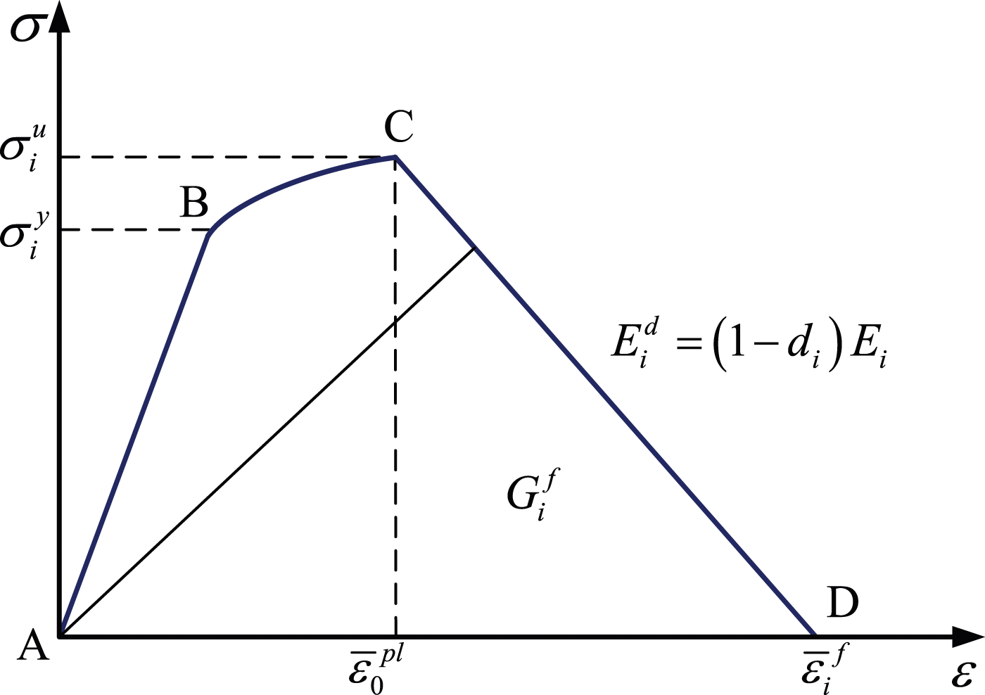
The interphase modulus with damage (


In the simulation, the shear plane is defined as the geometrical surface where elements are deleted to produce the chip, i.e., the separation surface between chip and workpiece, as shown in Figure 4. The line of depth of cut is taken as the baseline, which is used to determine the shear plane angle with the separation surface of chip. After completing the simulation, the shear plane angle The shear plane in the simulation of CFRP cutting at the fiber orientation of (a) 0°, (b) 45°, (c) 90° and (d) 135°.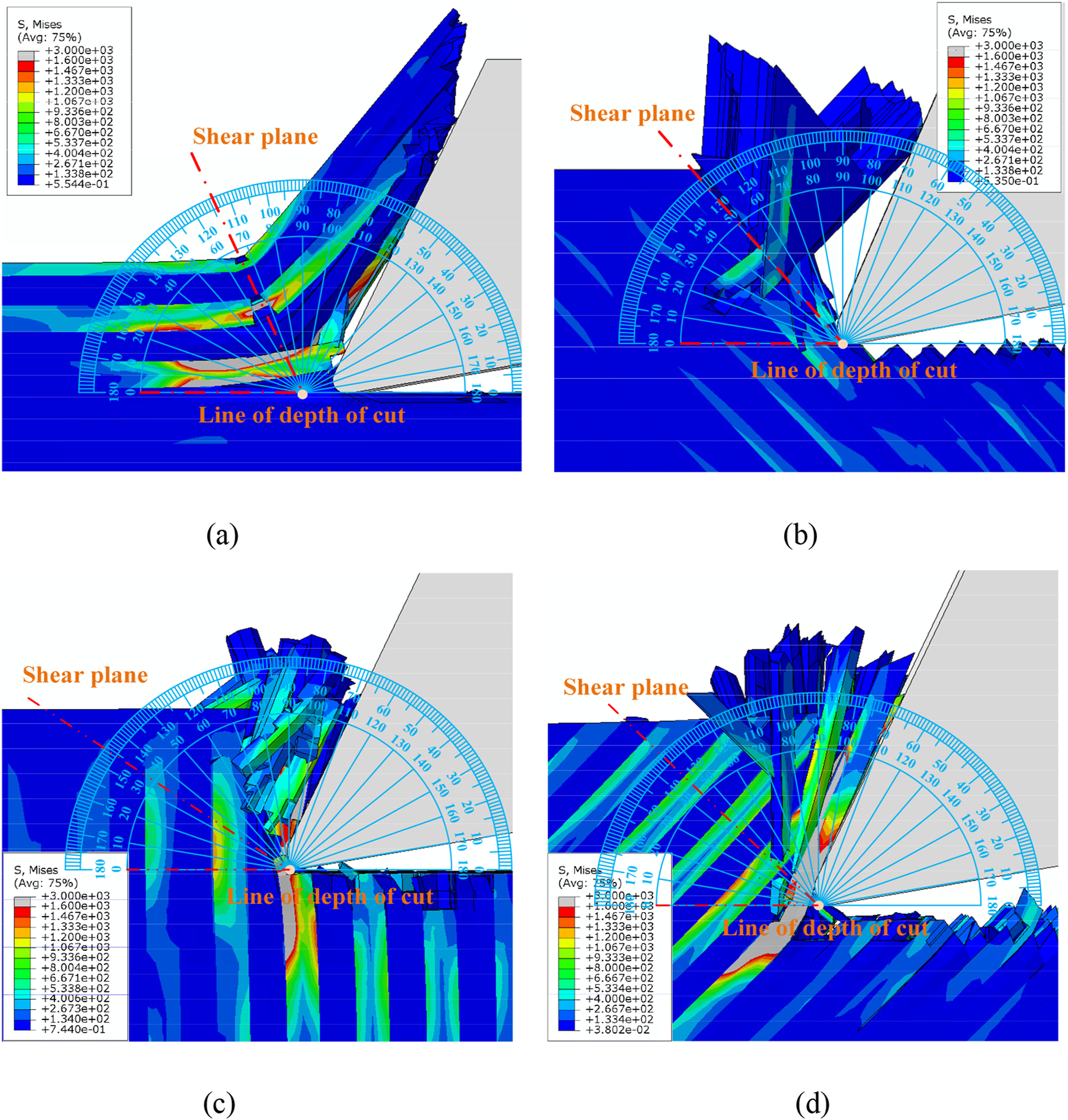
Force coefficients determination
Friction angle
It is known that the angle between the resultant force and the normal force acting on the rake face is defined as the friction angle, 
Based on the experimental Variation of the friction angle with the fiber orientation.

It can be seen that the predicted function aligns reasonably well with the experimental results across the entire range of fiber orientations. The value of
Shear plane angle
It can be observed from Figure 1 that the chip is formed by the shear fracture of the workpiece, and the shear fracture occurs along a theoretical shear plane that makes an angle of
Based on the results of the shear plane angle in the cutting simulation of UD-CFRP (see Section on “Simulation modelling”) and the experimental measurements obtained from sources,6,28 the variation of Variation of the shear plane angle with the fiber orientation.

The proposed function can capture the general trend of the shear plane angle in the analyzed fiber orientations, with the exception of the 30° fiber orientation. On the other hand, the assumed values of the shear plane angle are also presented in Figure 6, in which the shear plane angle
Shear strength
The shear strength Variation of the shear strength with the fiber orientation.

Comparing with the constant shear strength used in sources,4,24 the proposed function is relatively closer to describing the relationship between shear strength and fiber orientation. Meanwhile, the theoretical calculations of shear strength
Rebound height
As shown in Figure 1, the rebound height Variation of the rebound height with the fiber orientation.

The fairly good agreement between predictions and measurements suggests that the proposed function can accurately assess the rebound height for fiber orientations ranging from 0° to 180°. It is obvious that extremely low rebound heights are detected when the fiber orientation exceeds 90°, which implies that the fibers still bounce back, but the effect is considered limited. Consequently, the corresponding component force can be obtained by using the function of the fiber orientation-dependent rebound height.
Experiment verification
Experimental setup
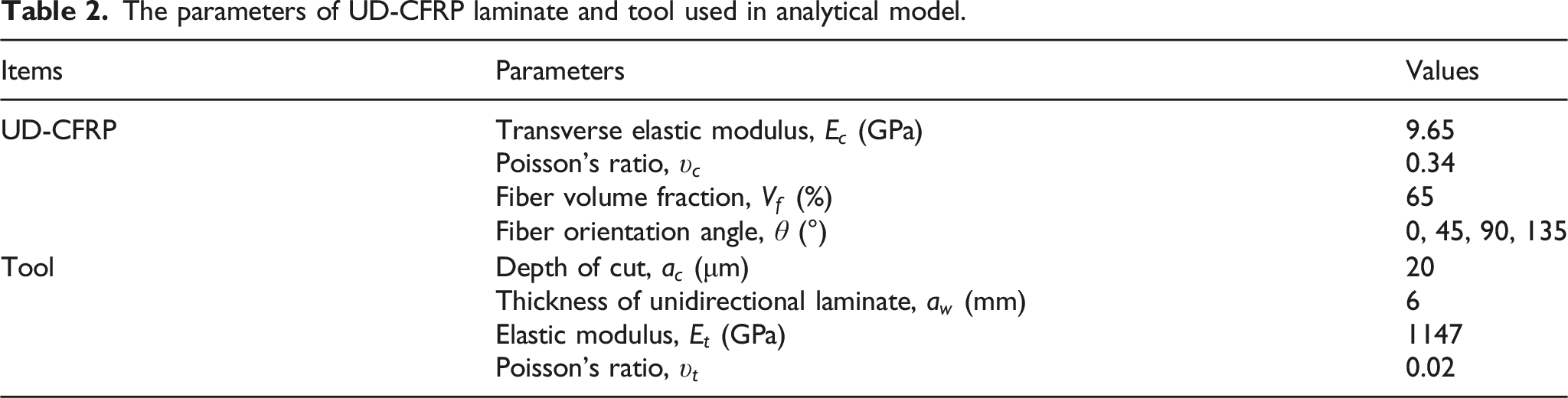
As shown in Figure 9, the machining experiments of UD-CFRP were conducted on a CNC machining center, in which the UD-CFRP laminates had fiber orientations of 0°, 45°, 90°, and 135° with a cutting thickness of 6 mm. It is noted that the UD-CFRP laminate was fabricated using the autoclave processing method. The curing profile involved heating the sample at a rate of 1.5°C/min for 100 min, maintaining the temperature at 180°C for 150 min, and then cooling it down to room temperature at a rate of 1.5°C/min. The 0.06 MPa vacuum pressure was maintained throughout the curing process of the composite samples. The machining process was performed using a diamond-coated cemented carbide cutting tool with a speed of 157 m/min, a rake angle of 20°, and a flank angle of 10°. The cutting conditions in the simulation were kept the same as in the tests. The other parameters used for the UD-CFRP laminate and tool are provided in Table 2. The Kistler 9272 dynamometer is used to measure the cutting force in each test, and the average value is calculated as the effective one after five repeated cutting trials. The Hitachi S-3400N scanning electron microscope (SEM) is utilized to analyze the machined surface area, where the depth of cut and the actual depth of cut may vary. The height measurement of the area where spring back occurs is obtained, i.e., the vertical distance between points A and B (Figure 9). The point A is the intersection of the flank face and the line of the actual depth of cut, while point B is the intersection of the cutting edge and the line of the depth of cut. Schematic of the experiment setup for CFRP composites. The parameters of UD-CFRP laminate and tool used in analytical model.
Model prediction and validation
The comparison between the predicted cutting forces and the experimental data, along with error bars, for various fiber orientation angles is illustrated in Figure 10. It can be observed that the theoretical values reasonably match the measurements within the fiber orientations range of [0°, 180°], in which the relative error is lower than 14.8%, except for the thrust force at 90°. Figure 10(a) shows that both the cutting force Comparison between the experiments and predictions of (a) cutting force and thrust force and (b) rakeface force and flankface force with fiber orientation.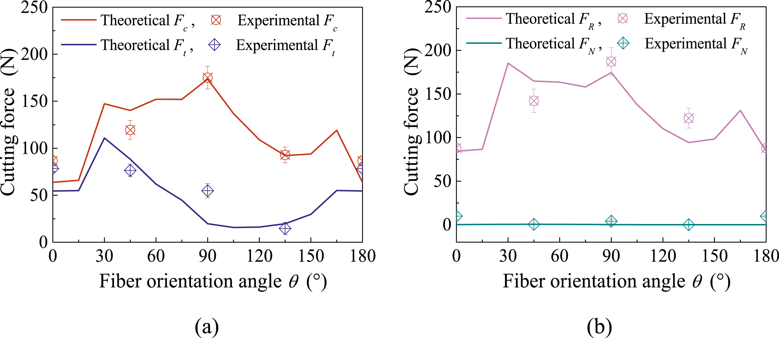
The predictions of the rakeface force
Furthermore, the comparison between the predicted values and the measurements of friction angle and rebound height with error bars for different fiber orientation angles is presented, as shown in Figure 11. It is found that the predictions of the proposed function for the friction angle and rebound height (see equations (18) and (21)) closely match the experimental values. It is worth noting that the experimental friction angle was obtained through the reverse tangent calculation of the friction coefficient, which was evaluated based on the variation curve of maximal Comparison between the experiments and predictions of (a) friction angle and (b) rebound height with fiber orientation.
Results and discussion
Figure 12 shows the impact of rake angle on the cutting force and thrust force across the entire range of fiber orientation. It is found from Figure 12 that there is a first turning point in the curve of predicted cutting force and thrust force for the fiber orientation range of [0°, 90°], which is attributed to the change in the chip formation mode. The inflection point value decreases as the rake angle increases. For instance, the turning point value changes from 60° to 45° when the rake angle range shifts from [0°, 5°] to [10°, 15°]. And the value further decreases to 30° as the rake angle reaches 20° (see Figure 10(a)), which means that a larger rake angle is beneficial for the transformation of chip formation mode to occur earlier, resulting in a decrease in cutting force. Meanwhile, the second turning point is also observed for the fiber orientation range of [90°, 180°], in which the inflection point varies from 150° to 165° as the rake angle increases within the range of [10°, 15°]. These phenomena reflect that the rake angle strongly influences the variation of the cutting force and the thrust force, both of which decrease as the rake angle increases across the fiber orientation between the two turning points. Conversely, the cutting force and the thrust force increase with the rise of the rake angle within the fiber orientation range from 0° to the first turning point and from the second turning point to 180°. Effect of rake angle on the (a) cutting force and (b) thrust force for different fiber orientation in machining CFRP.
Figure 13 shows the impact of flank angle on the cutting force and thrust force within the fiber orientation range of [0°, 180°] with a rake angle of 20°. It is evident that the cutting force and the thrust force influenced by the flank angle are limited. The trends of the cutting force and the thrust force show that both forces decrease as the fiber orientation range increases from 0° to 180°. The flank angle has a significant effect on the thrust force compared to the cutting force, which indicates the interaction between the workpiece and the tool’s flank face is more likely to act in the normal direction of the machined surface. Moreover, the inflection point value in the curve of predicted cutting force and thrust force will not change with the increase of the flank angle. This implies that the change in chip formation mode may be independent of the flank angle throughout the fiber orientation. This implies that the elastic bouncing back effect of CFRP on the flank surface is the main factor affecting the variation of cutting force and thrust force. Effect of flank angle on the (a) cutting force and (b) thrust force for different fiber orientation in machining CFRP.
Conclusions
The numerical-analytical method was used to derive the mechanical model for cutting force in machining UD-CFRP laminates. Experimental measurements were conducted to validate the model, and the results indicate good agreement between the predicted and experimental values, with relative errors below 14.8%, except for the thrust force at 90°. The force coefficients, such as friction angle, shear plane angle, shear strength, and rebound height, were strongly influenced by the fiber orientation. The results of the functional modeling align well with the experimental findings.
The impact of rake angle and flank angle on the cutting force and thrust force was also investigated. Two turning points were observed in the curve of predicted cutting force and thrust force across the entire range of fiber orientation, and the position of inflection points changed with the increase in the rake angle. It can be further observed that a larger rake angle is beneficial for the transformation of chip formation mode to occur earlier, resulting in a decrease in cutting force. Additionally, the impact of flank angle on cutting force and thrust force is limited, and these forces decrease as the flank angle increases within the fiber orientation range of [0°, 180°]. The inflection points in the curve of predicted cutting force and thrust force remain constant with the increase in flank angle. This indicates that the change in chip formation mode is not influenced by the flank angle. Furthermore, the results obtained from UD-CFRP laminates can be utilized to investigate the changes in cutting force and shear plane angle during the machining of multi-directional CFRP (MD-CFRP) laminates.
Footnotes
Declaration of conflicting interests
The author(s) declared no potential conflicts of interest with respect to the research, authorship, and/or publication of this article.
Funding
The author(s) disclosed receipt of the following financial support for the research, authorship, and/or publication of this article: This research work was supported by the Zhejiang Provincial Natural Science Foundation of China (LQ21E050006), the Special Project of Center for Scientific Research and Development in Higher Education Institutes of Ministry of Education (No. ZJXF2022174), the Basic Public Welfare Research Project of Zhejiang Province (LGG19E050010), the Scientific Research and Cultivation Fund Project of Hangzhou City University (204000-58162208).