
Abstract
Hat-stiffened composite skins have been widely used in primary structures of aircraft components. The bonding strength at the stiffener-skin interface is critical to ensure the advanced load-bearing capacity of the stiffened skin, whereas, the deltoid regions are usually the weakest locations because of the geometrical singularity. Inserting fillers into the deltoid regions could alter the bonding strength. In this study, a series of four-point bending tests are conducted on the co-cured hat-stiffened composite skin specimens with and without fillers and with different pre-fabricated debonding defects, furthermore, finite element simulations are implemented to predict the failure process. The stiffness, initial failure load, failure mode and failure process are analyzed to obtain the influences of the fillers on the damage tolerance of the hat-stiffened composite panels, and the influential mechanisms were revealed by the combined analyses of the test and simulation results. It is found that the usage of fillers can increase the initial stiffness of the panel without prefabricated defects by about 10%, but provide limited influence on the initial failure load. The pre-fabricated debonding defect along longitudinal direction has little influence on the stiffness and failure load, but the influence of the defect along transverse direction are higher. The initial failure of all hat-stiffened composite panels with/without filler and with/without prefabricated defects under four-point bending onsets around the deltoid region. The usage of the fillers changed the load transfer and the stress status in the deltoid region of the hat-stiffened composite panels and as a consequence, the initial failure modes were changed and the failure load were increased by the fillers. This work provides a technical support for the damage tolerance design and strengthening method of hat-stiffened composite structures.
Introduction
Nowadays, carbon fiber reinforced plastics (CFRP) are increasingly implemented in the aerospace primary structures for weight reductions. Composite stiffened panel is an assembly of serval composite stiffeners and a composite skin, in which the stiffeners are attached or bonded to the composite skin. The stiffeners can improve the strength and rigidity greatly, which makes the stiffened panels have very high structural efficiency. 1 Besides that, the composite stiffened panel can be fabricated by co-curing technologies and thus decreases the manufacturing cost, which makes stiffened composite panels to be common in all thin-walled lightweight structures. 2
Typical shapes of the stiffeners include “I”, “J”, “L”, “T”, “Z” and hat (omega), etc. Compared with the former five open-sectional stiffeners, the hat stiffeners are in close section and exhibit higher torsional rigidity and strength-to-weight ratio.3–8 In addition, the hat stiffeners have many other advantages, i.e., (1) the special geometrical configuration allows a greater spacing of the stiffeners due to their own width; (2) the enclosed space between the stiffener and the skin can effectively be utilized as a duct for the passage of cables; (3) the minimal fuel loss when used in wet bays; (4) compatible with most composite prepreg systems; (5) OML tooling approach easy to design and use; (6) the contour can be relatively easy to control. 9 In one word, the hat stiffeners have clear advantages over the open-sectional stiffeners, which makes them to be one of the most widely used structure concepts in the fuselages and wings of airplanes.
As the geometric features of the hat-stiffeners and conventional composite manufacturing techniques, it is inevitable to form either an open or enclosed void between the curved stringers and panels, often referred to as a deltoid. An empty deltoid, especially when accompanied by a geometrical singularity, is disadvantageous from the aspect of structural integrity. 10 Moreover, the stiffened panels used in the fuselage are in complex loading during service, which includes both in-plane and out-of-plane loads. The stiffened structure could buckle under in-plane compressive or shearing load, and the buckling deformation induces twisting moments or bending moments, which leads to out-of-plane stresses and stress concentration at the stiffener-panel interface. Therefore, stiffener-panel debonding failure usually occurs at the interface between the panel and stiffener flanges.
Filling deltoid with some conformal resin, fabric composite, or a bundle of rolled unidirectional carbon fibers, also known as a filler or a noodle, can somewhat attenuate or even eliminate the problem caused by the geometrical singularity and thus provide additional structural reinforcement.11,12 In recent years, many studies have been carried out on the effects of the fillers on the stiffened composite panels. For example, Sapi et al. 13 provided a review on the filler materials and the role of fillers and the effect of filler’s parameters on the performance of out-of-plane of joints. Kundan et al. 14 tested T-joints in the pull mode till the failure and assessed the efficacy of integrally woven 3D inserts. It was observed that the effects of the fillers on the initial failure load were little, whereas the normalized strength with integrally woven 3D inserts was enhanced by about 30% when compared the T-joints without the insert. Sápi et al. 15 introduced eight novel filler concepts and experimentally validated against the baseline filler (noodle) via T-joint tensile tests. According to their study, the effects of the different fillers on the damage tolerance, the failure initiation load, strength were discovered. Li et al. 16 investigated the damage process of T-joints with 3D4D braided fillers under tensile load, and they found the crack initially occurred in the interface between L-ribs and the fillet at the top of the trigone and extended along the arc edge of the L-ribs to the interface between the soleplate and the overlaminate. The initial failure load of T-joints with 3D 4D braided composite fillers was 35.6% higher than the T-joints filled unidirectional carbon fiber prepreg fillers. May et al. 17 conducted T-pull tests on the composite T-joint with braided carbon fiber noodle, they found the damage is initiated in the curvature of the fillet and slightly above the fillet and then propagates along the web as well as in the flange-skin interface. Heimbs et al. 18 conducted quasi-static and high-rate dynamic tensile tests on the composite T-joints and found the usage of PEI filler leads to a significant improvement with 23% higher energy absorption of 98 J compared to the carbon braid filler. Li et al. 19 investigated the effect of the filler’s size and found the strength of stiffener-skin intersection increased by 87% as the filler diameter was increased from 0 to 2.79 mm, but the strength decreased significantly when the diameter of filler exceeded 2.79 mm.
Most of the previous researches are based on coupon level test, which cannot represent the complex geometries and loading conditions in the real structures. Yetman et al., 20 Bertolin et al. 21 and Li et al. 22 conducted four-point bending tests separately on the hat stiffened composite panels and obtained the fracture behavior at the component level, and they found the mode I delamination occurs at the free end of the stiffener, delamination forms at the inner corners of the stiffeners and the skin are mode II slip-shear type, which highlighted that the variability seen in fracture properties at coupon level was less evident in structural component response. Nevertheless, no studies have been found on the effects of the fillers on the damage tolerance of the hat-stiffened composite panels at the component level. Current transport airplane structural design practice should comply with damage tolerance methodology according the FAA regulations, and it is necessary to further understand the influences of the fillers on the mechanical properties of the damaged hat-stiffened composite panels. Both four-point bending tests and numerical simulations are carried out for hat-stiffened composite panels with different filling and damage conditions in this study, so as to investigate the effects of the usage of fillers on the damage tolerance of the hat-stiffened panel at component level. This work can provide a technical support for the damage tolerance design of hat-stiffened composite structures.
Test article description
Configurations of the specimens.


Geometric features of the Hat-stiffened composite skin specimen (all dimensions in mm).
Mechanical properties of T800/X850 composite materials.

Experimental studies
Four-point bending tests were conducted using MTS E45.105 material testing machine referring to the test standard, ASTM D7264.
23
The test setup is shown in Figure 2 and the site-photo is shown in Figure 3. The diameters of the four rollers are all 10 mm. The two outside rollers are supporting rollers and the two inner ones are loading rollers. The two supporting rollers were clamped by the stationary head of the material testing machine, while the two loading rollers were clamped by and moved together with the movable head of the testing machine. Bending load was produced to the specimens when the two loading rollers were pushed downward by the movable head of the testing machine. A quasi-static displacement control load was applied with a constant rate of 1.0 mm/min. The environmental temperature was maintained at (23 ± 5)°C, and the relative humidity was at (55 ± 5)% during tests. The sampling rates of the load, displacement and strains were all set to 10 Hz. Four-point bending test setup (all dimensions in mm). The site-photo of four-point bending test.

The loading sequence was as below: the specimen was center-aligned through adjusting the relative position of the specimen to the loading system firstly, then decreased the load to about 20 N. Finally, the specimens were loaded till to meet the termination conditions. The center-alignment criterion was the differences of the readings of the four strain gauges shown in Figure 2(b) being less than 5% as the readings were around 900 μ. After the specimens were center-aligned, the load was dropped down to 20 N but not 0 N to avoid the possible movement between the specimens and loading system. Different loading termination strategies were used in order to capture the progressive damage processes and detect the damage after tests. As for the specimens of the configure-1 shown in Table 1, the load was kept proceeding till the ultimate load dropped by 40% of the peak load. As for the specimens of the other five configurations shown in Table 1, the loading of the first two specimens were stopped as the load dropped more than 5% of the peak load value, the loading of another two specimens were stopped as the appearance of visual inspectable damage, the loading of the last two specimens were kept proceeding till the ultimate load dropped by 40% of the peak load.
Test result analysis and discussion
Load-displacement curves
The load versus displacement relationships of the hat-stiffened panel under four-point bending are shown in Figure 4. From Figure 4, it can be seen that the consistencies of the load-displacement curves of all groups of tests are quite good before the initial failure occurs. All the corresponding displacement of the load point as the initial failure occurs is about 12 mm and the load values are generally between 500 N and 600 N, which means the initial failure bending moments are between 25,000 N⋅mm and 30,000 N⋅mm (the arm of force is 50 mm long according to Figure 2). After the initial failure, the specimens maintain the support to a quite high load, together with a progressive failure process. The final displacement corresponding to the ultimate load can be more than 40 mm, which indicates that the debonding failure at the stiffener-skin interface is in a progressive way and the stiffened panel can still absorb a large amount of energy after its initial failure. Load-displacement curves of the four-point bending test specimens.
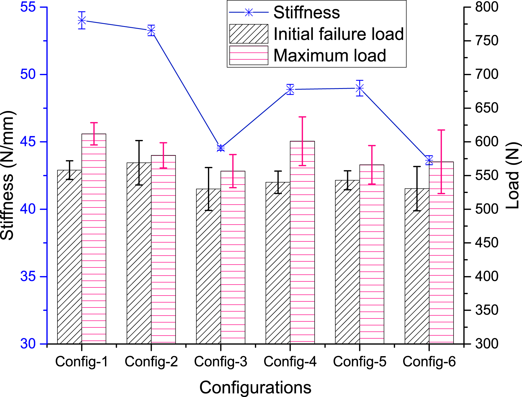
Stiffness and failure loads
The changing of the mean values and standard deviations of the stiffened panels’ stiffness and failure loads under four-point bending are shown in Figure 5. The initial stiffness is obtained in accordance with equation (1) as below. Test results of different the different panels.
The mean values and standard deviations are obtained through the equations from (2) to (3).

s n−1 = Sample standard deviation;
n = number of specimens, and
x i = measured or derived property.
The initial failure load is defined as the load value that the load suddenly drops more than 5% in the loading process. The load values are fluctuated slightly during the loading process but that value is not treated as failure load. This is because the fluctuations are mainly caused by the relative slide between the specimen and the rollers or small local damage in the contact regions between the specimens and loading fixtures, and the testing samples can still sustain much higher load after these load fluctuations. The maximum load is defined as the peak load value throughout the whole loading process, which is just a little higher than the relevant initial failure loads. It should be noted that, since the initial failure loads but not the maximum failure loads will be used to evaluate the interface strength of the stiffener-skin, the loading on the specimens were stopped with different termination criteria, therefore, the maximum load values shown in Figure 5 cannot be treated as evaluation metrics. Another benefit of stopping the tests in different conditions is the failure process can be seen in the tested samples.
From Figure 5, it can be seen the consistencies of the stiffness and failure load values of all groups of tests are rather good, and the fillers can increase the stiffness and the initial four-point bending failure load of the hat-stiffened composite panel by about 10% and 3.3% respectively. The type-1 pre-fabricated defect has little influence on the stiffness, while the type-2 pre-fabricated defect decreases the stiffness by 17.5% and 10.7% respectively for the hat-stiffened panel with and without filler. The initial failure load is not clearly decreased by the type-1 pre-fabricated defect, on the contrary, it is increased by the type-1 defect. The initial failure load is decreased by about 5.0% and 1.7% respectively by the type-2 defect. This indicates the two different kinds of pre-fabricated defects attenuate the stress concentrating level at the stiffener-skin interface and hence, postpone the failure initiation.
Failure modes
Failure modes of specimens with different pre-fabricated conditions.


Typical failure process of the Hat-stiffened composite skin under four-point bending.

Debonding results of the four-point bended specimens: (a) With filler and no defect; (b) With filler and type-1 defect; (c) With filler and type-2 defect; (d) Without filler and no defect; (e) Without filler and type-1 defect; (f) Without filler and type-2 defect.
Finite element modelling
Mesh generation
A three-dimensional finite element model was established for simulating the four-point bending of the hat-stiffened composite panel using the commercial finite element code, Abaqus,
24
which is shown in Figure 8. The finite element model consists of a hat-stiffened composite panel specimen and four cylindrical analytical rigid surfaces. The four cylindrical analytical rigid surfaces were all with a diameter of 10 mm and a length of 40 mm, which were used to simulate the loading and supporting rollers, which are also shown in Figure 2. The pre-fabricated disbond defects were defined through decreasing the strength and fracture toughness values of the cohesive elements in the debonding area to 0.01 times of those undamaged elements. The finite element model of the hat-stiffened composite skin.
Elements in the hat-stiffened composite skin impact model.

Eight-node in-plane continuum shell elements with enhanced hourglass control and reduced integration, SC8R, were used to model the composite hat-stiffener and the panel to avoid the shear locking problem and to increase the computing efficiency. The stiffener was simulated as SC8R elements and eight-node three-dimensional cohesive elements (COH3D8). The two adjacent plies with 0° ply angle were modelled as one layer of element to save the calculation cost. COH3D8 elements were used to model the inter-lamina relationships inside the composite stiffener and the interfacial relationship between the stiffener and the panel. Seven layers of COH3D8 elements were located between the two adjacent layers of SC8R elements and share nodes with the SC8R elements. The panel was simulated as four layers of SC8R elements. Each layer was used to simulate three plies of lamina to save the calculation cost. There were no cohesive elements incorporated in the panel mesh since there was no delamination failure there according to the tests.
There was one layer of COH3D8 elements at the interface between the stiffener and panel, which was tied to the surfaces of the stiffener and panel respectively to simulate the stiffener-panel bonding conditions at the interface. The two fillers were simulated as six-node three-dimensional solid wedge elements with enhanced hourglass control and reduced integration, C3D6R, and 6-node linear triangular prism elements, C3D6. The surfaces of the filler were tied to the adjacent surfaces of the panel and stiffener to simulate the bonding conditions at the filler-stiffener and the filler-panel interfaces. The four rollers were modelled as R3D4 elements.
Constitutive models and material parameters
Intralaminar failure criteria
Hashin’s failure criteria. 18
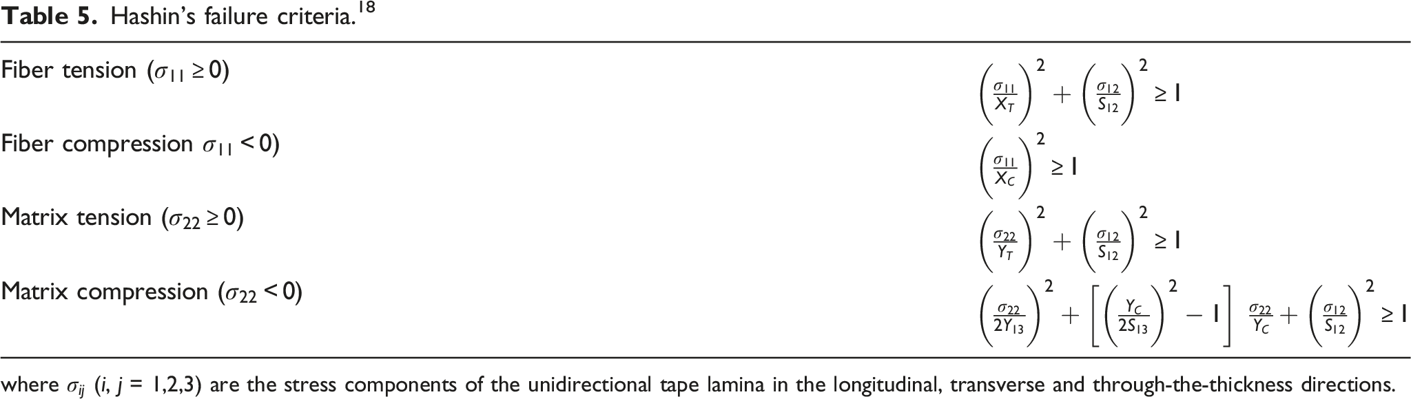
where
Interlaminar failure and debonding
Since the stiffened composite panel specimens were manufactured by co-curing process, same material parameters and failure criteria were used to simulate the delamination damage inside the stiffener and the stiffener-panel debonding failure. The cohesive zone model, which combines both a strength-based and a fracture mechanics-based criteria, was used to predict onset and propagation of interlaminar cracks. The interface started to degrade once the stress at interface increases to its strength, and the degradation of the interface properties involves energy dissipation. Once the energy dissipated by surface area is equal to the fracture toughness of the interface, a new free area will be created.
Ye’s criterion
26
was used as strength degradation initiation criterion to predict the onset of the degradation process, which is written as equation (4) below.

The interface of adjacent plies would be fully degraded when the energy dissipated equals to the fracture toughness. The B-K criterion
27
was implemented to predict the damage propagation under mixed-mode loading conditions, as shown as equation (6). The value of η, which is power exponent, is set to be 1.45.
In ABAQUS, the damage factor D (SDEG: Scalar stiffness degradation, 0 ≤ D ≤ 1) is introduced to characterize the degree of damage for the cohesive element.24,28 The stiffness coefficient (K) in damage evolution is expressed by
Material parameters of the cohesive elements.

Contact relationships
“Hard” contact was used to define the normal interaction properties of the contact to avoid penetration during the analysis process. Penalty friction formulation was used to define the tangential interaction properties of the contact. The friction coefficients between the composite panel and the steel impactor and that between the composite panel and the wood fixture were set to be 0.1 and 0.3 respectively. The surface-to–surface contact was used to define the contact relationships between the four cylindrical rollers and the upper and lower surfaces of the panel.
Boundary conditions and simulation algorithm
The two outer supporting cylindrical rigid surfaces shown in Figure 8(a) were set to be fixed, while the two inner loading ones were applied a downward displacement loading. Nonlinear static algorithm was used to simulate the quasi-statical four-point bend loading process.
Simulation results
Comparison of the deformation process between simulation and test results
The comparisons of the simulated and experimental load-deflection relationships of the composite skin-hat stiffeners subject to four-point bending are shown in Figure 9. Only one typical sample’s test results of each configuration were chosen to compare with the simulation results so as to make the comparison to be clearer. It should be also noted that the simulation results do not include the post failure process to save the CPU time, and the simulations of the initial failure mode are the primary objects of the current work. From comparisons, it can be concluded that the proposed model can be used to simulate the deformation and failure processes reasonably well, in terms of stiffness and onset of delamination damage. Comparisons of the simulated and experimental load-deflection relationships of the composite skin-hat stiffeners subject to four-point bending.
Failure modes and mechanism
Initial failure modes of stiffened-panel specimens with different pre-fabricated conditions.
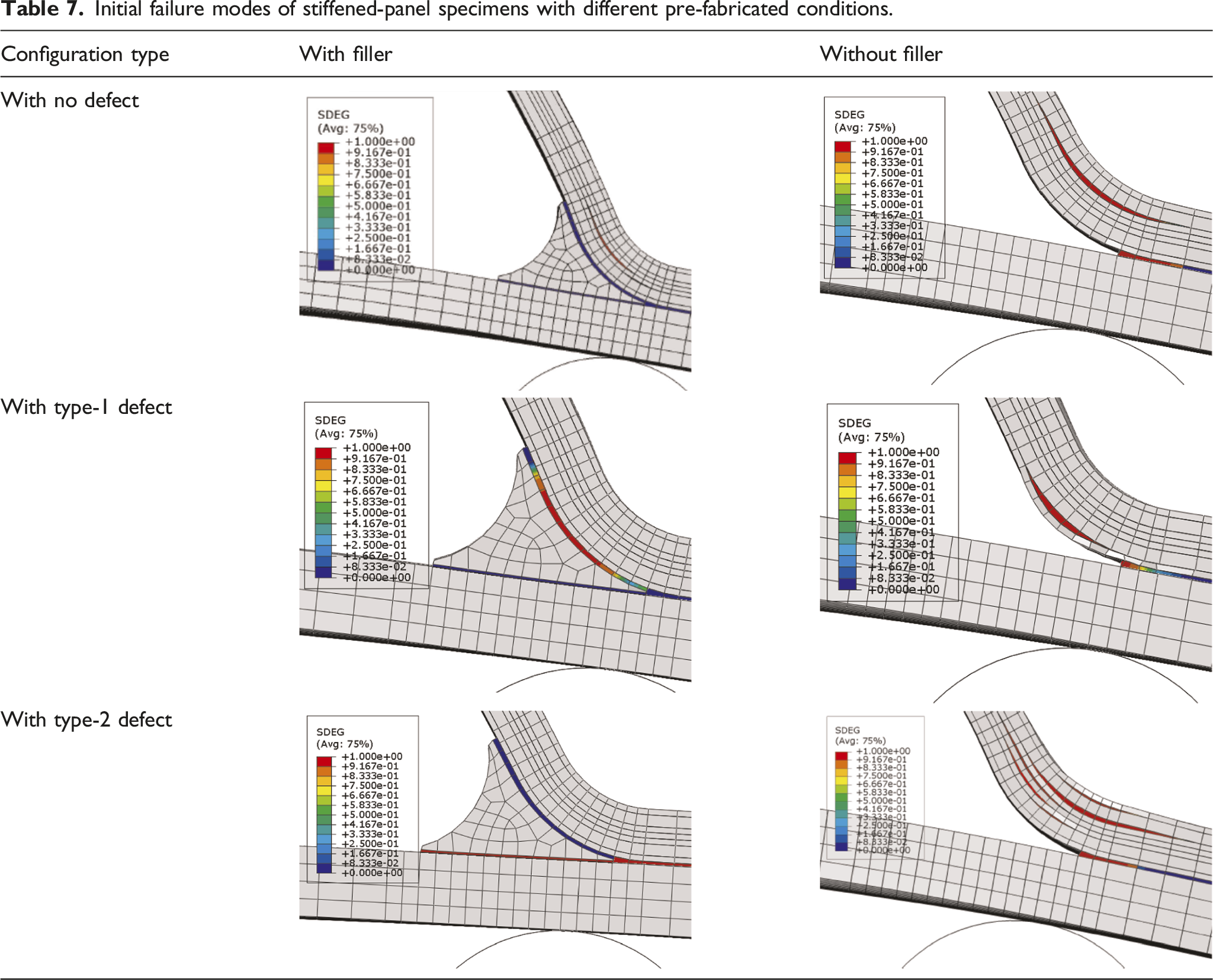
From the Table 7, it can also be seen that the initial failure modes and the failure locations of the panels were also changed by the pre-fabricated defects. The failure usually onsets at the weakest point and the pre-fabricated defects promote the initiation of the failure. The delamination cracks in the deltoid region of the stiffener opens, which indicates that the four-point bending load generated not only shear stresses, but also out-of-plane tensile stresses between different plies of composite stiffener in the deltoid region. Whereas, both the stiffener-filler disbond and the stiffener-panel disbond does not open, which indicates that these two locations of disbond are induced by shear stresses and the fillers mainly transfer compression and shearing load between the stiffener and skin.
Conclusions
Base on the work presented, the following conclusions can be drawn. 1. A four-point bending test method has been proposed to evaluate the bond strength between the hat stiffener and composite panel at component level with high repeatability and reliability of the test results. Six configurations of hat-stiffened composite panel articles with different filling conditions and prefabricated debonding statuses have been tested, in which the stiffness, initial failure load, and failure modes of the test results exhibit a high consistency. 2. The usage of fillers can increase the initial stiffness and the initial failure load by about 10% and 3.3% respectively. The type-1 defect has little influence on both the stiffness and failure load, but the type-2 defect has a large influence on both of them. 3. The finite element simulation method has been developed and proposed to predict the failure process of the hat-stiffened composite panel under four-point bending and was validated against the corresponding experimental results. Furthermore, the failure mechanisms have been discussed with the test and simulation results. 4. The initial failure of all six different hat-stiffened composite panels under four-point bending onsets around the deltoid region. The usage of the fillers changed the load transfer and the stress status in the deltoid region of the hat-stiffened composite panels and as a consequence, the initial failure modes were changed and the failure load were increased by the fillers.
Footnotes
Acknowledgements
The authors would like to thank the National Natural Science Foundation of China (Grant No. 52075326, U1637105).
Declaration of conflicting interests
The author(s) declared no potential conflicts of interest with respect to the research, authorship, and/or publication of this article.
Funding
The author(s) disclosed receipt of the following financial support for the research, authorship, and/or publication of this article: This work was supported by the National Natural Science Foundation of China (Grant No. 52075326, U1637105).