
Abstract
For closed-hole panels such as hat-stiffened panels, it is inevitable to use mandrels during the manufacturing process. However, the uniformity of pressure transmission of the silicone rubber mandrel with the prefabricated hole is not good, the vacuum bag mandrel is easy to be broken and wrinkled, the water-soluble mandrel is high in cost, and the invar steel metal mandrel is difficult to demold. To solve these problems, this article proposed a new method for co-curing carbon fiber-reinforced resin matrix composite hat-stiffened panels by using a silicone airbag as a mandrel through autoclaves. Firstly, the thermo-force-flow multi-field coupling finite element model of co-curing carbon fiber-reinforced polymer (CFRP) hat-stiffened panels was established by using finite element software. The co-curing process of hat-stiffened panels was simulated and studied. The influence of different thickness of silicone airbag mandrels on the wall thickness and pressure of the workpiece were found to be relatively uniform in the new process. Then, the autoclave experiment was carried out to verify the correctness of the finite element model. Lastly, the interfacial bonding strength test was carried out to verify the mechanical properties of the parts. In summary, the practicability of co-curing CFRP hat-stiffened panels with silicone airbag male mandrels was proved in this article. The precision of CFRP hat-stiffened panel was efficiently promoted by this new process.
Introduction
Carbon fiber composite is a lightweight, high-strength, and high-performance material. It has a series of advantages such as high-temperature resistance, corrosion and fatigue resistance, high-specific strength, good damping and shock absorption ability, good damage safety, designability, and multifunctional integration. Therefore, it is widely used in aircraft, and its usage has become one of the advanced indicators for evaluating aircrafts. 1
The reinforced wall panel structure of the composite can be generally divided into T type, L type, J type, and hat type (Ω-type) according to the shape of the truss. The hat-stiffened panel has better structural stability, higher efficiency for the axial load transfer and buckling strength than other types, making it the first choice for tubular structures such as fuselage sections. 2 Hat-stiffened panels are widely used in most aircrafts, such as the rear side panels of the C919.
Carbon fiber hat-stiffened panel mainly has co-bonding, secondary bonding, and co-curing methods. Co-curing molding has a small number of methods using autoclaves, which greatly reduces the cost, and co-curing does not require glue adhesive, so good interface mechanical properties, lightweight, and small deformation can be obtained, which is beneficial for heavy weight and precise size requirement structures like aircraft fuselage section. However, co-curing inevitably requires the use of a mandrel structure, many scholars have also conducted research.
For open-type stiffened panels, such as T-, J-, I-shaped reinforced wall panels, it is difficult to calculate the radius and volume of a triangular filler, and the inconsistency between the reinforcement bar and the panel tends to occur during co-curing process. Many scholars have done a lot of research. Wang et al. studied the effects of pressure distribution, packing, tool assembly scheme, and the overall forming process on the compaction of T-reinforced panels. 3 -5 Ma et al. studied the compaction effect of the T-shaped stiffened panel triangle by vacuum-assisted resin infusion/prepreg co-curing process. 6 Zou et al. studied a new method for curing carbon fiber reinforced polymer CFRP by high pressure microwave. 7 Zhou et al. studied the effect of filler radius on the forming quality of T-stiffened panels. 8 Elaldi et al. studied a new method of forming J-stiffened panels. 9 Bai et al. studied the impact properties of a co-cured J-shaped stiffened panel. 10 Peng et al. studied the structure of the mold and the control of the forming process to improve the quality of the parts. 11 Ye et al. studied the curing scheme, pre-adhesive material, and curing parameters of the co-bonding process of I-stiffened panel. 12 Hong et al. adopted a new molding process to shape the I-reinforced panel and J-reinforced panel. 13 However, these open-hole types are easy to demold, and the molding method are not suitable for the molding of closed-hole types such as hat-stiffened panels.
For the closed-hole hat-stiffened panels, issues such as difficulty in demolding and low manufacturing precision should be urgently solved. Xu et al. studied the co-bonding, secondary bonding, and co-curing of the hat-stiffened panels by thermocompression curing. 14 Tarfaoui and Moumen studied a new type of adhesive to improve the co-bonding properties of the hat-stiffened structure. 15 Kim et al. studied the influence of the metal mandrel and silicone rubber mandrel on the bearing pressure of the hat-stiffened parts, but did not study the influence of the shape of the mandrel on the forming quality. 16 Xun et al. used vacuum bags as auxiliary airbags to co-cure hat-stiffened panels. Due to the tendency of wrinkles and leaks in vacuum bag mandrels, they are now being phased out by factories. 17 Xiao et al. invented a low-cost water-soluble mandrel to make hat-stiffened panels. The water-soluble mandrel has less thermal deformation, which can well maintain the shape of the hole in the forming process, and it is convenient to demold, but the water-soluble core mold itself is of poor quality and is prone to rupture during the experiment, so that the surface quality of the inner wall surface of the hat-shaped part is poor, and it has not been put into production. 18 Li and Zhou et al. studied the process of silicone rubber mandrels with prefabricated round holes, analyzed the shape of the hat-shaped long truss under this process, and found that the shape of the hat-stiffened panel was difficult to control. The reason was that the silicone rubber mandrel with prefabricated holes exerted pressure through its own thermal expansion, which tended to cause uneven pressure on the hat body, induced dimensional defects or defects in precision, and the process adjustment was difficult. 8,19,20
The above research studies have achieved certain results, but there are still many problems. 21 The pressure transmission of the silicone rubber mandrel with the prefabricated hole is uneven, the airbag mandrel is easy to leak, the cost of water-soluble mandrel is high, and the invar metal mandrel is difficult to demold. Secondary bonding and co-bonding need to use the autoclave more often, which will cause waste of energy and low efficiency of the process.
To address these issues, a new process of using silicone airbag male mandrel was proposed. The finite element simulation of the co-curing process was carried out, and the hat-stiffened panels were manufactured. Then, the interfacial bonding strength test was conducted. The influence of mandrels with different thickness on the quality of parts was studied. The pressure distribution at some key points during the experiment was analyzed. It provides a theoretical basis and experimental verification for co-curing hat-stiffened panels.
Experiment
Prepreg material
The materials used for CFRP hat-stiffened structure are C135 unidirectional prepreg and BCP200 fabric prepreg produced by Shandong Ding Sheng Composite Technology Company (China). The substrate material is DS1207.3 heat-resistant prepreg special for epoxy resin. The properties of the materials provided by the company are presented in Table 1.
Prepreg properties.
Hat-stiffened structure and mold
Hat-stiffened structure and layup
The hat-stiffened structure is shown in Figure 1. The hat-stiffened panel is composed of hat-stiffened long truss and skin plate.

CFRP hat stiffened panel. (a) Composition of CFRP hat-stiffened panel and (b) measurements of CFRP hat-stiffened panel.
The unidirectional prepreg is laminated with the woven prepreg using axial direction as 0°. The stacking sequence of the hat part is [±45°/0°/90°/0°/90°/0°/90°/0°/±45°], and the stacking sequence of the plate is [±45°/±45°/90°/−45°/±45°/45°/0°/45°/±45°/−45°/45°/90°].
Principle of new curing process
The principle of the new process is that the hat-shape long truss is placed in the frame mold and the silicone airbag mandrel is placed in the hat-shaped closed aperture mold. The silicone airbag mandrel is inserted into the canister pressure of the autoclave to support the formation of hat-shaped long truss, and the skin mold is placed at the bottom of the preformed material to function as a temperature uniform skin. The mold placement and curing package are shown in Figure 2. The curing temperature and pressure curve are shown in Figure 3.

Co-curing process of hat-stiffened structure with autoclave.

Processing curve.
The advantage of this scheme is that the hat-shaped long truss is placed in the frame mold, and the position in the width direction is positioned by the cavity frame mold, which has higher dimensional accuracy; the silicone airbag mandrel has uniform pressure transmission because of the thin wall structure, and it is easy to place and extract in the closed aperture mold.
Mandrel preparation
The silicone airbag mandrels were produced using the mold shown in Figure 4. Different sizes of mandrel (Figure 4(a) to (c)) were selected to match the shell mold (Figure 4(d)) and the cover mold (Figure 4(e)) to produce the silicone airbags with different thicknesses. The appropriate amount of 881# silica gel solution is mixed with curing agent according to the mass ratio of 100:2.5, stirring evenly then pour it into the mold. The silica gel begins to solidify after half an hour and takes out 6–8 h later after complete curing. The properties of the silicone rubber provided by the company are presented in Table 2. The silicone airbags with different thicknesses (1, 2, and 3 mm) are shown in Figure 5.

Mandrel manufacturing mold. (a) mandrel for 1 mm airbag, (b) mandrel for 2 mm airbag, (c) mandrel for 3 mm airbag, (d) cavity mold, and (e) cover plate.
Properties of 881# silicone rubber.
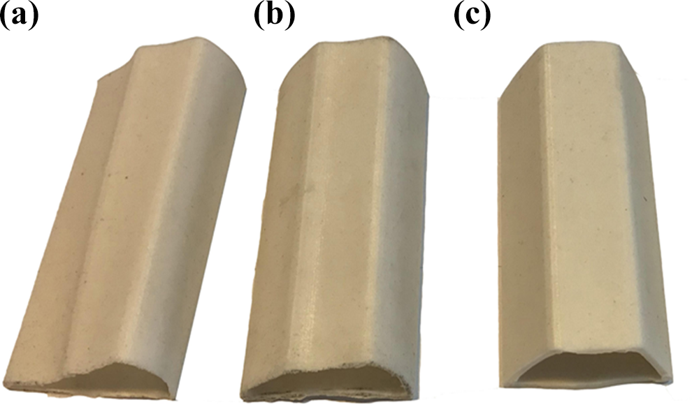
Silicon rubber mold. (a) 1-mm-thick airbag, (b) 2-mm-thick airbag, and (c) 3-mm-thick airbag.
Design and manufacture of steel molds
The long truss mold is a frame cavity mold made of Q235 steel, and the skin mold is a plate mold made of Q235 steel. The long truss mold and the skin mold are shown in Figure 6.

Steel mold.
Finite element modeling
Thermal conduction and solidification kinetic equation
In the curing process of carbon fiber-reinforced resin matrix composites, the temperature field and the curing reaction of the resin play a major role in the internal stress and pore defects of the stiffened panels. The temperature field is mainly determined by the external heat source, the exothermic heat of the resin curing reaction, and the heat exchange between the materials.
Based on the Fourier heat conduction law, the thermochemical model considered the effect of the resin solidification exotherm on the temperature field during the curing process:


where
The kinetic equation of resin curing reaction is:

where
Finite element model
COMSOL Multiphysics is a large-scale advanced numerical simulation analysis software released by Comsol in Sweden. It is a widely applied commercial multi-physics coupling analysis software.
The porous medium heat transfer, the curing generalized partial differential equation, and the porous elastic module of the Comsol software were used to model and simulate the co-curing process of carbon fiber-reinforced resin matrix composite hat-stiffened panels.
Since the axial solidification process was basically the same to reduce the calculation workload, this simulation used a two-dimensional simulation. To accurately reflect the deformation of the hat-stiffened panels in the curing process with the autoclave, it was necessary to add relevant boundary conditions to the steel mold and the silicone mandrel:
The outer surface 1 of the prefabricated parts, the upper surface 2 of the skin mold, and the inner surface 3 of the silicon were loaded with a curing temperature curve as shown in Figure 3, and the remaining boundaries were thermally insulated.
The surface 1 of hat-stiffened long truss was in direct contact with the frame mold, so a fixed constraint was added. Since the side surfaces 4 and 6 were symmetric, a symmetrical constraint was added; since there was more than one hat-shaped long truss, so the side surface 5 was symmetrically restrained in the horizontal direction.
The curing pressure was set to 0.6 MPa on the bottom surface 2 of the steel mold and the inner surface 3 of the silicone mandrel.
The article also performed finite element modeling on a hat-stiffened panel made from a silicon mandrel with a 12.5-mm preformed aperture. As boundary conditions, a pressure of 0.1 MPa was set in the preformed apertures, and the rest was not changed.
For the two models above, the grid was divided by a free-form quadrilateral mesh. The mesh of the mold and the prefabricated parts are shown in Figure 7.

(a and b) Finite element meshing.
Implementation plan
Co-curing experiments were carried out by placing silicone airbag mandrels with different thicknesses, and then the parts were dimensioned and analyzed. On the basis of the experiment, the influence of thickness of silicon airbag on pressure and deformation of the parts were analyzed by finite element numerical simulation, and the solidification forming mechanism of the new process was explained. Furthermore, we compared the results of the finite element displacement map of the silicone airbag mandrel with preformed aperture mandrel to indicate the advantages and disadvantages of the two processes.
Results and discussion
Shape and thickness analysis
The shape and thickness of the hat had a great influence on the mechanical properties of the hat-stiffened panels, so the shape of the hat had to be analyzed. The effects of different mandrel thicknesses (1, 2, and 3 mm) on the shape and thickness of CFRP hat-stiffened panels were compared and analyzed through experimental research.
It can be seen from the cured hat-stiffened panel that the surface was smooth for all probes, and no abnormal occurred. The results of the size measurement are shown in Figure 8. The height of the inner wall of the workpiece was between 30.28 mm and 30.44 mm, and the basic deviation was less than 2%. The vertical distance from the triangle to the edge of the hat was between 49.08 mm and 49.17 mm, compared with 48.16 mm in the structural design, the deviation was almost 2%, and the forming result was good.

Experimental results of appearance accuracy test of hat-stiffened structures: (a) with 1 mm thickness mandrel, (b) with 2 mm thickness mandrel, and (c) with 3 mm thickness mandrel .
Took the top, the edge, and the bottom of the hat from the parts formed under different thickness respectively, and selected four points for the histogram, the results are shown in Figure 9. In Figure 9(b) to (d), it can be seen that the minimum size of the four points was 1.17 mm, the maximum was 1.22 mm, the deformation was 0.05 mm, and the basic deviation was almost 4%. The maximum deformation of the bottom of the hat was 0.04 mm, and the basic deviation was 2%. The deformation of these three places in the hat were all less than 4%. Hence, the dimension fluctuations in this new method were smaller.

(a to d) Size changing chart of hat-stiffened parts.
Analysis of finite element results
The finite element simulation of the new process was conducted, and the displacement diagrams of the silicone mandrel were obtained. Since the expansion of the mandrel changes little and is not easy to observe, we draw 20 times enlarged diagrams of the hat-stiffened panels, as shown in Figure 10. It can be seen from Figure 10 that the largest deformation region was the triangular region, and the deformation at the top of the hat was the second. Figure 10(b), (d), and (f) shows that as the wall thickness of the silicone airbag increased, the deformation of the stiffened panels also began to increase. The maximum displacement (accuracy: 0.001 mm) of the triangle area was changed from 0.035 mm to 0.09 mm; the displacement of the hat top was also increased from 0.02 mm to 0.07 mm. The amount of expansion at the same temperature was larger when the thickness of the silicon airbags was larger.
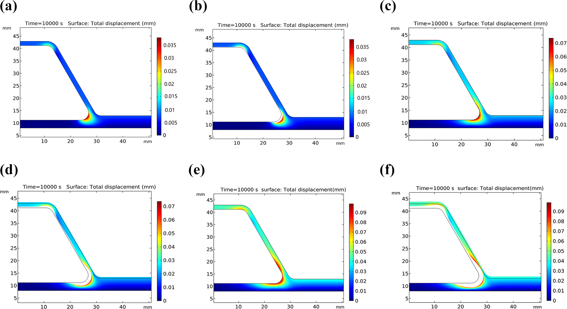
Maximum displacement diagram and 20 times enlarged diagram of CFRP hat stiffened panels. (a) 1 mm thick, (b)1 mm thick magnified 20 times, (c) 2 mm thick, (d) 2 mm thick magnified 20 times, (e) 3 mm thick, and (f) 3 mm thick magnified 20 times.
In conclusion, the maximum deformation in the triangle area and the hat shoulder were small, and hence were basically negligible, indicating that using the silicone airbag as a mandrel was effective.
The CFRP hat-stiffened panels using a silicone mandrel with a 12.5-mm preformed aperture were modeled as shown in Figure 7(b). After simulation, the finite element displacement map is shown in Figure 11. After analysis, it was found that under the same process conditions, the maximum size deformation of the triangle with the preformed silicone mandrel was 0.25 mm, which was 2.8 times that of the 3 mm thickness airbag molded parts, 3.6 times of the 2 mm thickness airbag molded parts, and 7.1 times of 1 mm thickness airbag molded parts.

(a) Maximum displacement diagram and (b) 20 times enlarged diagram of hat-stiffened panel manufactured by 12 mm prefabricated aperture mandrel.
It indicated that the new process proposed in this article was better than the preformed aperture process.
Hat pressure analysis
The pressure and its uniformity in the solidification process had a great influence on the property of the part, and it had to be analyzed. According to the finite element simulation results, the pressure of the top of the hat A, the bottom B, the triangle C, and the flange D were taken to draw the pressure curve to analyze the effects of the silicone airbag mandrels with different thicknesses on the pressure and its uniformity. The results are shown in Figure 12.
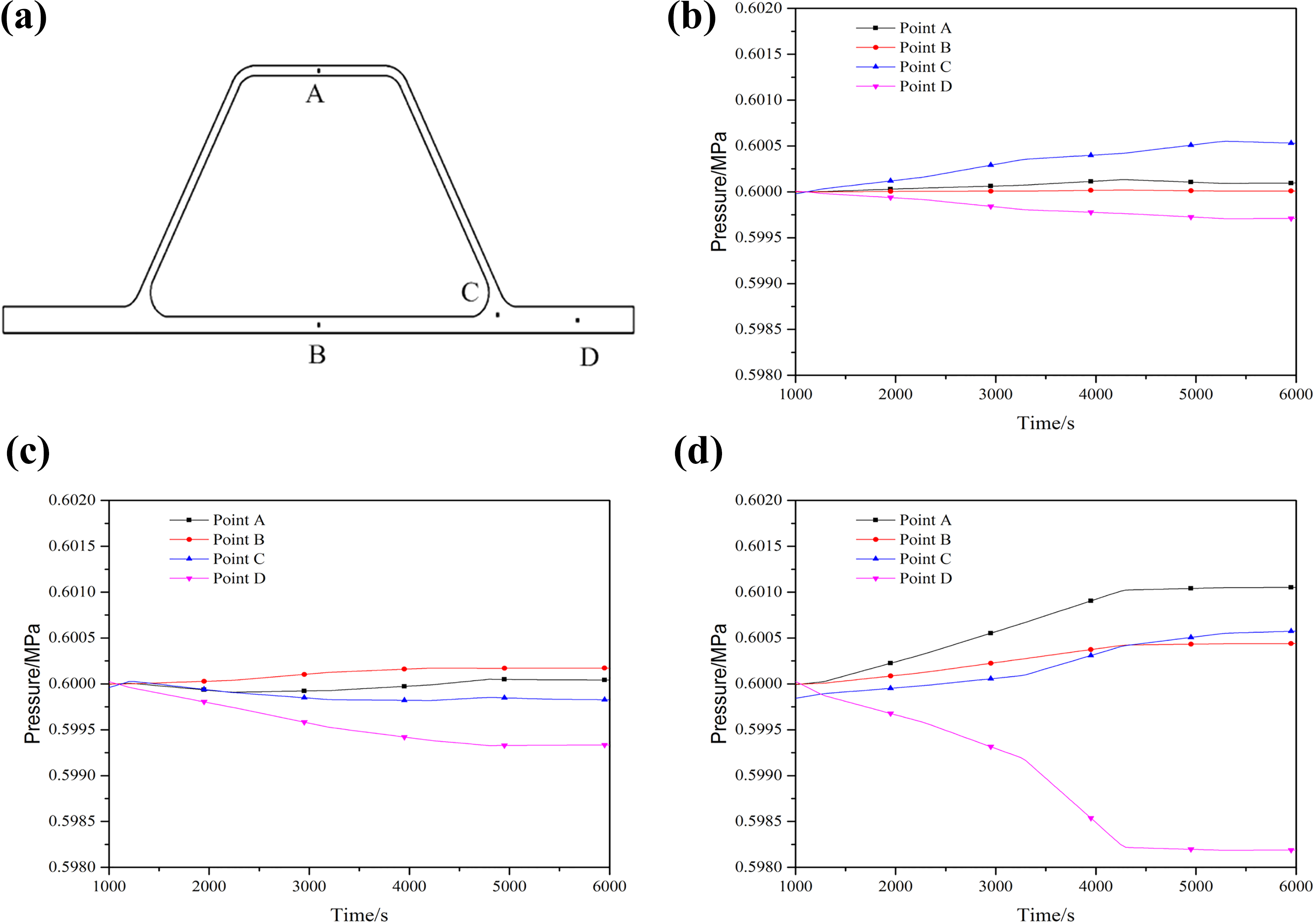
Pressure diagram of different points of hat-stiffened parts: (a) pressure measuring points, (b) 1 mm, (c) 2 mm, and (d) 3 mm.
As it can be seen from Figure 12(b), the pressure at the point C of the triangular region is the largest, because the lower surface 2 of the skin is fixedly restrained, the upper surface is subjected to the pressure of the can and the expansion force of the silicone rubber. The force of point A at the bottom of the hat is relatively uniform with the processing time. The reason is that the top of the hat is pressed by the tank and subjected to the upward expansion of the silicone rubber. The B point at the bottom of the hat has the most uniform force. This is because, the B point is pressed by the tank at the both sides and subjected to the expansion of the silicone rubber. Therefore, the force here is closer to 0.6 MPa than the point A. As shown in Figure 12(b) to (d), as the wall thickness increases, the force at point D in the lying area becomes lower because when the wall thickness increases and the thermal expansion of the silicone rubber becomes larger, this offsets the part of the tank pressure.
From Figure 12, it can be seen that the pressure range (accuracy: 0.0001 MPa) of the molded parts of the 1–mm-thick silicone airbag mandrel was 0.5997–0.6006 MPa, the pressure range of the 2 mm thick silicone airbag mandrel was 0.5993–0.6002 MPa, and the pressure range of the 3-mm-thick silicone airbag mandrel was 0.5982–0.6011 MPa. When the thickness of the silicone airbag mandrel was larger, the pressure range of the workpiece was bigger. But the pressure at four points was basically around 0.6 MPa, and the fluctuation was small, and the hat-stiffened structure had a uniform curing pressure, so the size was uniform, consistent with the thickness measured before. The hat was also free of distortion, which can maintain the initial design dimensions, demonstrated the feasibility of the new process further.
Bonding strength analysis
The parts prepared in this article are hat-stiffened panels and the hat is used to enhance the mechanical properties of the base skin. The interface between the hat and the skin not only acts as a bridge but also a transmitter of the mechanical properties of the workpiece. The bonding strength of the interface seriously affects the quality of the part and determines whether the part meets the requirements for use. Therefore, the tensile strength test of the interface is required in this chapter. We used MTS810 drawing machine to carry out the drawing experiment on the parts manufactured by different silicone airbag mandrels.
Figure 13 is the load–deflection curve of tensile test. The drawing force reaches the maximum of 2.07 kN when the thickness of silicone mandrel is 1 mm and the displacement is 1.6 mm. When the thickness of silicone mandrel is 2 mm and the displacement is 2.35 mm, the drawing force reaches the maximum of 1.89 kN. When the thickness of silicone mandrel is 3 mm and the displacement is 2.15 mm, the maximum tensile force is 1.73 kN. The tensile force in Figure 13 appears to rise again after falling, which is due to ductile fracture between the stiffener and the skin.
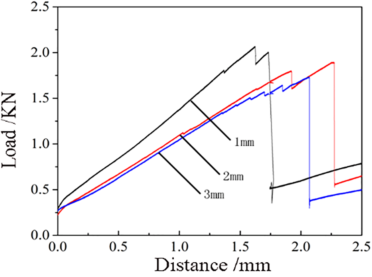
Load–deflection curve of tensile test.
The results of tensile tests showed that the larger the wall thickness of silicone mandrel, the worse the interfacial bonding strength of hat-stiffened panel. This is because when the thickness of the mandrel increased, the expansion force caused by the mandrel will increase during the heating process, and the greater the pressure on the triangle area, resulting in the weakening of the interfacial bonding strength to a certain extent.
According to the calculation of the tensile load in Figure 13, the pull-out stresses of 1, 2 and 3 mm mandrel are shown in Figure 14. The pull-out stress is 2.094, 1.92, and 1.756 MPa, respectively. This means that the larger the wall thickness, the smaller the pull-out stress.

Pull-out stress diagram.
Conclusions
The workpiece manufactured with different thicknesses (1, 2, and 3 mm) silicone airbag mandrels were compared through experimental research, and the thickness deviation of the top, the edge, and the bottom of the hat were respectively 0.05, 0.03, and 0.04 mm. The wall thickness was relatively uniform.
The pressure at the four points of the hat were obtained through the finite element simulation analysis, and the pressure range of the molded parts with different wall thickness was approximately 0.5997–0.6006 MPa (1 mm), 0.5993–0.6002 MPa (2 mm), and 0.5982–0.6011 MPa (3 mm), and the parts were under relative uniform pressure.
In summary, the size and thickness of the experimental parts and the pressure of the finite element simulation results is relatively uniform with processing time, which proved the feasibility of the autoclave co-curing CFRP hat-stiffened panels with silicone airbag mandrels.
This article provides a method for forming CFRP hat-stiffened panels using a silicone mandrel, which has good performance and high stability. Demold is easy, mold making process is simple and it can be used multiple times.
The correctness of the mathematical model and the finite element analysis method were verified by experiments, which provided theoretical and experimental support for the manufacture of composite hat-stiffened structures. The limitation of the study is that only the bonding strength have been tested. Other mechanical properties such as impact and compression properties have not been studied. The next research direction is to conduct research on impact resistance and observe the microstructure of the panels.
Footnotes
Acknowledgements
The authors would like to gratefully acknowledge the help of Yiyu Shao, Fubing Chen and Pingping Xie during the experiments and the support of KC Wong Magna Fund in Ningbo University.
Declaration of conflicting interests
The author(s) declared no potential conflicts of interest with respect to the research, authorship, and/or publication of this article.
Funding
The author(s) disclosed receipt of the following financial support for the research, authorship, and/or publication of this article: This work was supported by the Fundamental Research Funds for the Provincial Universities of Zhejiang (No. SJLZ 2021002), the National Basic Research Program of China (973 Program), the Natural Science Foundation of Zhejiang Province (Grant No. LY18E050006), the Natural Science Foundation of Ningbo City (Grant No. 2017A610088), and Ningbo Science and technology innovation 2025 major project (2018B10004, 2019B10100).