
Abstract
Cellulose nanocrystals (CNCs) and cellulose nanofibers (CNFs) extracted from rice stalks were added to poly-methyl methacrylate (PMMA) with weight ratios of 0.1–1.0 wt%. The tribological and mechanical properties of the resulting composite materials were evaluated and compared. The addition of CNCs and CNFs reduced the wear volume by around 72–90% compared to pure PMMA samples in ball-on-disk wear tests performed against a chrome steel ball counter body. The CNC and CNF reinforcements also effectively improved flow stress under static and dynamic deformation conditions. Furthermore, the flow stress enhancement increased with an increasing CNC/CNF addition for both composite materials. For a constant strain and strain rate, the maximum enhancement effect was observed in the samples reinforced with CNFs. Overall, the CNF/PMMA showed a better tribological and mechanical performance than the CNC/PMMA. In addition, the CNFs had a longer length and higher aspect ratio than CNCs, which led to a more effective mechanical entanglement effect with the PMMA matrix. This physical entanglement improved the structural integrity of the composites. The CNC reinforcement (CNC percentage from 0% to 1.0 wt.%) also enhanced an effective improvement of about 35%∼45% in yield stress and ultimate strength under dynamic deformation conditions and static deformation conditions. Furthermore, the CNF reinforcement (CNF percentage from 0% to 1 wt%) also enhanced an effective improvement of about double yield stress and ultimate strength under dynamic deformation conditions and static deformation conditions.
Introduction
Cellulose is the most common organic compound in nature and is readily found in plants, wood, algae, cysts, and bacteria. Cellulose exists in many different forms and has many advantageous properties, such as a high Young’s modulus, good crystallinity, and a high aspect ratio. As a result, nanocellulose materials are widely used throughout the paper-making, textiles, cosmetics, and pharmaceutical industries.1–4 Manmade nanocellulose materials can be broadly classified into two main types: cellulose nanofibers (CNFs) and cellulose nanocrystals (CNCs), wherein both cases, a conventional cellulose extraction process is first performed to remove components other than cellulose from the source lignocellulosic material. CNFs are generally prepared using high-energy mechanical methods such as high-pressure homogenization, ultrasonic vibration, and grinding.5,6 CNC and CNF are natural polymer materials extracted from rice straws. It has the characteristics of non-toxicity, high specific strength, and specific stiffness. Therefore, they are very suitable as an additive to composite, especially for environmental-friendly polymer composites such as PMMA.
There are many types of polymers, including both natural (e.g. silk, wool and DNA) and synthetic (e.g. nylon, polyester, and polyethylene). Some of these polymers exhibit plastic behavior due to their chemical structures, while others become brittle after being stressed at room temperature. Among the latter group of polymers, one of the most commonly used general-purpose plastics is poly-methyl methacrylate (PMMA). PMMA is a non-crystalline linear polymer that is glassy at room temperature with a penetration of about 92%, making it the most transparent polymer material,7–10 with Young’s modulus of around 3 GPa and tensile strength of 60–70 MPa. Compared with glass, PMMA not only has better transparency (around 92%) and higher impact resistance but also has only half the specific gravity. 11 Thus, PMMA is used for many applications, including LED lampshades, light guide plates for liquid crystal displays, aquarium display windows, artificial dentures, large sinks, airplane windows, and so on. Two molding methods are commonly used for PMMA. The first method is injection molding, in which the PMMA master batch is melted and injected into a hot mold by a screw. Once the cavity is filled, the PMMA takes on the form of the mold under the effects of compaction pressure and is then ejected from the mold and allowed to cool. Injection molding has the advantage that the finished products can take many shapes, including both simple and complex. However, the light transmittance is typically low. In the second method, initiators such as benzoyl peroxide (BPO) and azobisisobutyronitrile (AIBN) are added to methyl methacrylate (MMA) to form PMMA through a process of bulk polymerization. Compared to injection molded parts, the finished components have a higher light transmittance. However, they can only take simple shapes. One of the biggest disadvantages of PMMA, irrespective of the molding technique employed, is its lack of toughness, which results in the formation of brittle cracks in many applications and severely limits the application scope of the material.
In recent years, an increasing number of studies have investigated the use of nanocomposites as a matrix reinforcement material.12–17 In general, the results have shown that under ideal dispersion conditions, the contact area between the nanofiller and the matrix can be greatly increased for the same volume addition. Thus, even with a low percentage of filler material, it is possible to reduce the mean inter-particle distance significantly, thereby improving the toughness.18,19
Many engineering components fabricated of polymer (e.g. automotive, airplane and tissue engineering) are subject not only to static loads, but also dynamic loads during their service lives. However, while many studies have investigated the basic characteristics of composite materials,20–22 the behaviors of CNC/PMMA and CNF/PMMA composites under typical engineering conditions are still not fully clear. 23 Accordingly, in the present study, CNC/PMMA and CNF/PMMA composites were prepared with 0.1–1.0 wt% CNC/CNF reinforcement. The tribological properties of the various composites were investigated by ball-on-disk wear tests using a chrome steel ball counter-body. The flow stress behavior of the samples was then examined under quasi-static and dynamic loading conditions using a material testing system (MTS) and split-Hopkinson Pressure Bar (SHPB), respectively. The results provide a useful insight into both the role of nanocellulose in reinforcement and the reinforcement mechanism itself.
Experiment
Preparation of CNCs, CNFs, and nanocellulose/PMMA composites
The CNCs and CNFs were prepared in the laboratory using standard extraction and bleaching processes with agricultural waste rice straw as the raw material.
24
The schematic of preparation of CNCs and CNFs was demonstrated in Figure 1(a). The surfaces of the CNCs and CNFs were modified by TEMPO oxidation under different conditions in order to improve their hydrophobicity. Nanocellulose/PMMA composites were then synthesized by in-situ polymerization. Briefly, MMA monomer and 0.0333 wt.% of BPO initiator were poured into a pre-polymerization bottle and mixed by an ultrasonic oscillator for 1 min. The pre-polymerization bottle was then placed in a constant temperature water tank at 90°C with water circulation to initiate pre-polymerization. After 20 min, the bottle was removed and transferred to another water tank at a temperature of 25°C and left to cool for a further 20 min. Different quantities of CNC/CNF and dispersant (PEG 2000 & PEG 6000) were then added to the pre-polymerization bottle. The bottle was shaken intermittently with a 1000-W ultrasonic processor (UP-1200, LINKO, Australia) and was then returned to the 90°C water tank for 30 min to prompt a polymerization reaction. The bottle was shaken for 10 s every 5 min of the process. After the reaction process, the slurry in the pre-polymerization bottle was poured into a plate mold and placed in a constant temperature water tank at 70°C with water circulation for 3 h. Finally, the mold was heated in an oven at 90°C for 1 h to obtain the desired composite material. The graphical demonstration of the preparation process of PMMA composites was shown in Figure 1(b). Scanning electron microscope (SEM, JEOL, JSM-6700F, Peabody, MA, USA) and optical microscopy were used to observe the surface morphology of the composites. Fourier transform infrared spectrometer (FTIR, Thermo Nicoleti S5, iD7 ATR Accessory, USA) was used to study the structural properties of composites. (a) The schematic of preparation of CNSs and CNFs (b) The graphical demonstration of the preparation process of PMMA composites.
Tribological properties of nanocellulose/PMMA composites
The tribological behavior of the nanocellulose/composites was evaluated using a ball-on-disk tribometer (POD–FM406–10NT, Fu Li Fong Precision Machine, Kaohsiung, Taiwan). The upper ball rotates at a speed of 0.03 m/s with a normal load of 2 N for a 50 mm sliding distance. The tests were performed at 25°C and relative humidity of 70%. The upper ball is a 52100 chrome steel ball with a diameter of 6.31 mm, and the disk is the PMMA composites with a diameter of 25.4 mm and 5 mm thick. The size of specimens for static and dynamic testing are 5 × 5 mm cylindrical specimens (height × diameter). The friction coefficient of each sample was recorded continuously in real-time as the test proceeded. On completion of the test, the wear depth on the sample surface was measured using a 3D laser scanning microscope (VK9700, Keyence, Osaka, Japan). Three tests were performed under each of the experimental conditions.
Mechanical properties of nanocellulose/PMMA composites
The mechanical properties of the various specimens were evaluated under both quasi-static loads and dynamic loads. In the quasi-static tests, the specimens were deformed at strain rates of 10−3, 10−2 and 10−1 s−1, respectively, using a material testing system (MTS 810 series; MTS Systems Corporation, Minneapolis, MN, USA). In the dynamic tests, the specimens were impacted at strain rates of 3 × 10³, 4 × 10³ and 5 × 10³ s−1, respectively, using a split-Hopkinson Pressure Bar (SHPB) system (Long Win Science and Technology Corporation, Taoyuan, Taiwan) with the configuration shown in Figure 2. The size of specimens for static and dynamic testing are 5 × 5 mm cylindrical specimen (height × diameter).25,26 For each specimen, the stress-strain response was determined by measuring the incident, reflected and transmitted strain pulses using two strain gauges mounted at the mid-point positions of the input and output bars, respectively. We used three to five samples for each mechanical testing condition. The impact tests were performed at room temperature (25°C) in a lubricated condition. (Note that full details of the experimental setup, data acquisition process, and computational procedure are available in Lee and Lin,
25
Yang et al.,
26
Campbell and Ferguson,
27
Chen et al.,
28
, Chen and Wu,
29
and Kuo et al.
30
Experimental setup for SPHB impact tests.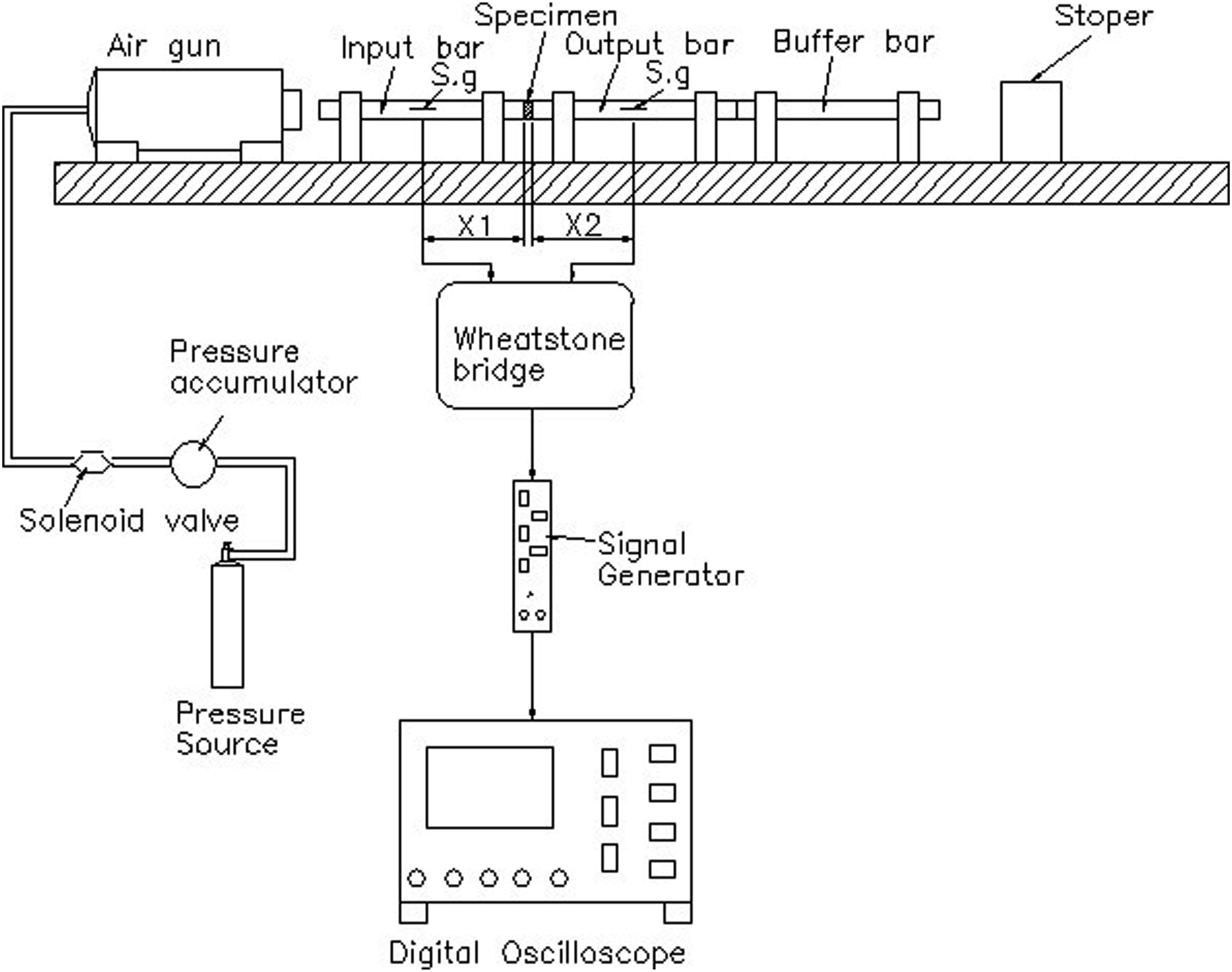
Results and discussion
Appearance of nanocellulose composites
Figure 3(a) and (b) present transmission electron microscopy (TEM) images of the as-prepared CNCs and CNFs, respectively. It is evident that, even though both nanomaterials were extracted from rice stalks, they have different dimensions and aspect ratios due to their different preparation processes. In particular, the CNCs have a length and aspect ratio of around 5 nm and 30, respectively, while the CNFs have a length of approximately 1 μm and an aspect ratio of around 100. The greater aspect ratio of the CNFs is to be expected since, in addition to crystalline segments, they also contain amorphous regions between the crystalline segments.
31
TEM images of (a) CNCs and (b) CNFs.
Structure of nano-cellulose/PMMA composites
Figure 4(a) and (b) presents scanning electron microscope images of the CNC/PMMA composites with 0.5–1 wt.% CNC addition. (Note that the sample was etched with oxygen plasma prior to observation to remove the PMMA from the surface of the composite and reveal the additive more clearly.) It is seen that the CNCs are partially aggregated and form a distributed network structure in the PMMA matrix. Figure 4(c) and (d) presents optical microscope images of the CNF/PMMA composite with 0.5–1 wt.% CNF addition. The CNF entanglements were observed. Figure 4(e) presents the FTIR of CNF/PMMA composites with 0.1 and 1 wt.% CNF addition. Among them, 1722 cm−1 is the tensile (C=O) of carbonyl groups, 1434 cm−1 is the bending vibration of CH2, 1260–1000 cm−1 is the tensile vibration of C-O (ester bond), and 950–650 cm−1 is the bending vibration of C-H, all of which are the characteristic signals of PMMA. With the increase in the amount of CNC, only 3000–3500 cm−1 feature peak signal intensity gradually increases, and the rest of the feature peaks remain almost consistent with PMMA. It is speculated that the hydrophobic PMMA is not compatible with hydrophilic CNF, and no bonding is generated. SEM images of (a) CNC 0.5 wt.%-PMMA (b) CNC 1 wt% -PMMA and OM images of (c) CNF 0.5 wt%-PMMA (d) CNF 1 wt%- PMMA composites (e) the FTIR of CNF/PMMA and CNC/PMMA composites.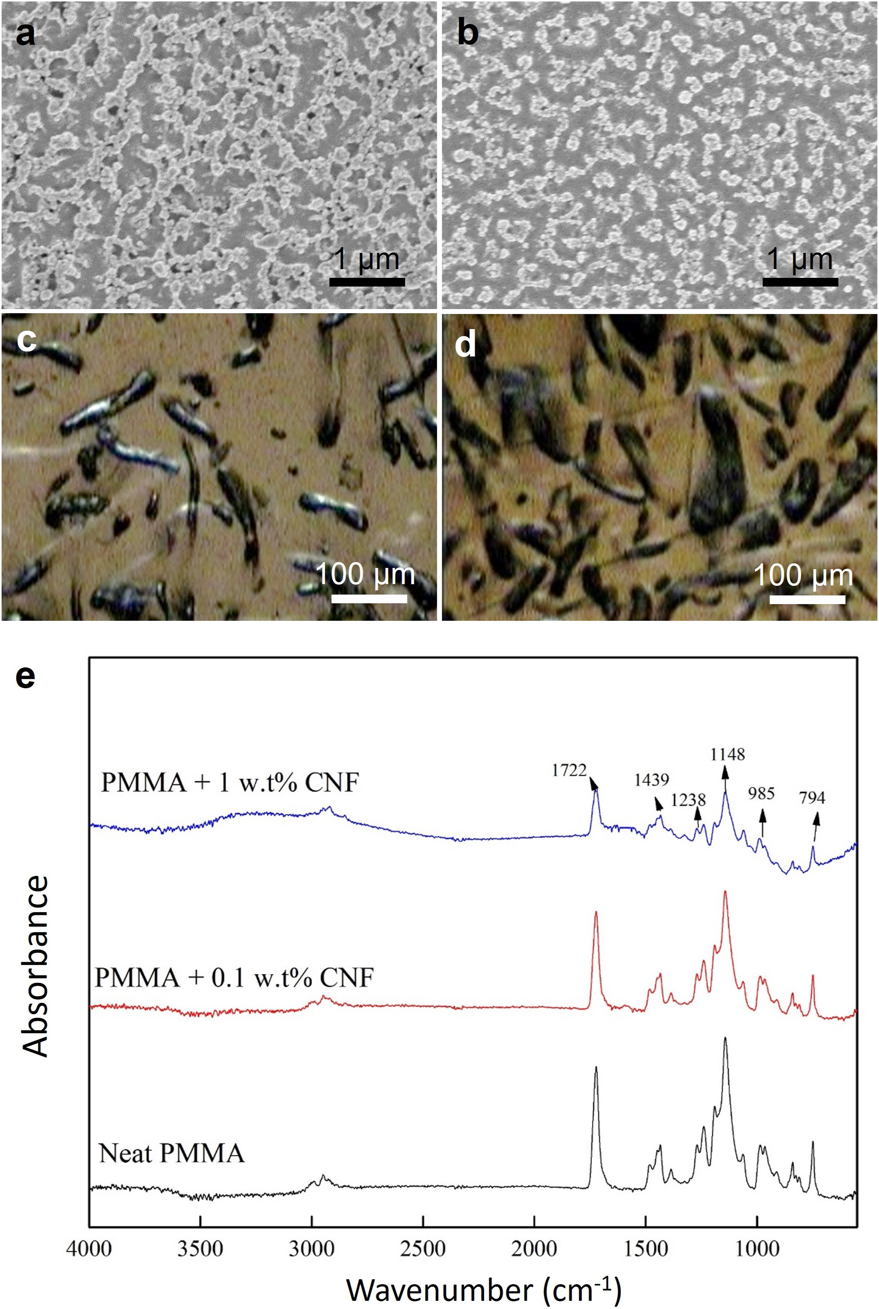
Tribological properties of nanocellulose/PMMA composites
Figure 5(a) compares the wear volumes of the nanocellulose/PMMA composites with various levels of CNC/CNF addition with that of a pure PMMA sample. Overall, the results show that the addition of nanocellulose reduces the wear volume by 72%–90%. Furthermore, for a given weight percentage of nanocellulose, the CNF samples yield a greater reduction in the wear volume. Similarly, in Figure 5(b), the average coefficient of friction of the nanocellulose/PMMA composite samples is lower than that of the pure PMMA sample, and the coefficient of friction of the CNF-based composites is lower than that of the CNC-based composites. Figure 5(c) shows the dynamic friction coefficients of PMMA composites. Tribological behavior of nanocellulose/PMMA composites: (a) wear volume and (b) average coefficient of friction; (c) The dynamic friction coefficients of PMMA composites.
The superior tribological performance of the CNF/PMMA composites can be attributed primarily to the larger length and aspect ratio of the CNFs, which improves their mechanical entanglement with the PMMA matrix and therefore increases the toughness. By contrast, the CNCs have a smaller aspect ratio and weaker bonding with the PMMA matrix. As a result, they readily break away from the matrix during sliding and degrade the third-body lubrication effect at the sliding interface accordingly. Overall, the results presented in Figure 5 show that the optimal tribological performance is obtained from the CNF/PMMA composite with the minimum CNF addition of 0.1 wt.%. Next, the tribology properties of composites can be further improved by adding environmentally friendly additives such as MoS2, graphene, and stereo-acid.32–34
Stress-strain behaviors of nanocellulose/PMMA composites
Figure 6(a)–(c) presents the true stress-strain behaviours of the CNC/PMMA specimens with different levels of CNC addition under quasi-static strain rates of 10−3 s−1, 10−2 s−1 and 10−1 s−1, respectively. For a constant strain rate, the flow stress increases with an increasing strain. Moreover, for given strain, the flow stress increases with an increasing strain rate. In addition, for a constant strain and strain rate, the flow stress increases with an increasing CNC addition. Similar tendencies are observed in the impact tests performed at dynamic strain rates of 3 × 10³, 4 × 10³ and 5 × 10³ s−1, as shown in Figure 7(a) and (b), respectively. It can be observed that the yield stress increase from 48 MPa to 98 MPa when the addition of CNC is increasing to 1.0 wt% (at the same stress rate of 10−3 s−1). It increased about 45% strength. It also observed that the strength under dynamic deformation also increased about to 50% (at strain rate of 6000 s−1, the yield stress increases from 98 MPa to 148 MPa). Furthermore, the ultimate strength also increase from 80 MPa to 123 MPa at the same strain rate of 10−3s−1 and increases from 200 MPa to 242 MPa at the strain rate of 6000 s−1 when the addition of CNF increase to 1 wt%. Figures 8(a)–(c) and 9(a)–(c) present the true stress-strain behaviours of the CNF/PMMA composites under quasi-static and dynamic strain rates, respectively. A similar tendency of the flow stress on the strain, strain rate and CNF addition is observed as that for the CNC/PMMA composites. It also can be observed that the yield stress increases from 48–159 MPa at the strain rate of 10−3 s−1 and the addition of CNF increases to 1.0 wt.%. It enhances the yield stress about double when the addition of CNF increases to 1.0 wt.%. Furthermore, the yield stress also increases from 98 MPa to 242 MPa at the strain rate of 6000 s−1. It also enhance double yield strength. Meantime, we can observe that the ultimate strength have about 65% enhancement in static and dynamic strain rate for CNF addition increase to 1 wt%. (80 MPa–170 MPa at strain rate of 10−3 s−1 and 200 MPa to 340 MPa at strain rate of 6000 s−1). The Tables 1, 2, 3, and 4 are presented the comparison of the Young’s modulus, yielding strength, and ultimate strength for CNC/PMMA and CNF/PMMA composites under quasi static strain rates and high strain rates, respectively. Stress-strain relationships of CNC/PMMA composites under strain rates of: (a) 10-3 s-1, (b) 10-2 s-1, and (c) 10-1 s-1. Stress-strain relationships of CNC/PMMA composites under strain rates of: (a) 4000 s-1, (b) 5000 s-1, and (c) 6000 s-1. Stress-strain relationships of CNF/PMMA composites under strain rates of: (a)10-3 s-1; (b) 10-2 s-1, and (c)10-1 s-1. Stress-strain relationships of CNF/PMMA composites under strain rates of: (a) 4000 s-1, (b) 5000 s-1 and (c) 6000 s-1. Comparison of the young’s modulus, yielding strength, and ultimate strength for CNC/PMMA composites under quasi-static strain rates. Comparison of the young’s modulus, yielding strength, and ultimate strength for CNC/PMMA composites under high strain rates. Comparison of the young’s modulus, yielding strength, and ultimate strength for CNF/PMMA composites under quasi-static strain rates. Comparison of the young’s modulus, yielding strength, and ultimate strength for CNF/PMMA composites under high strain rates.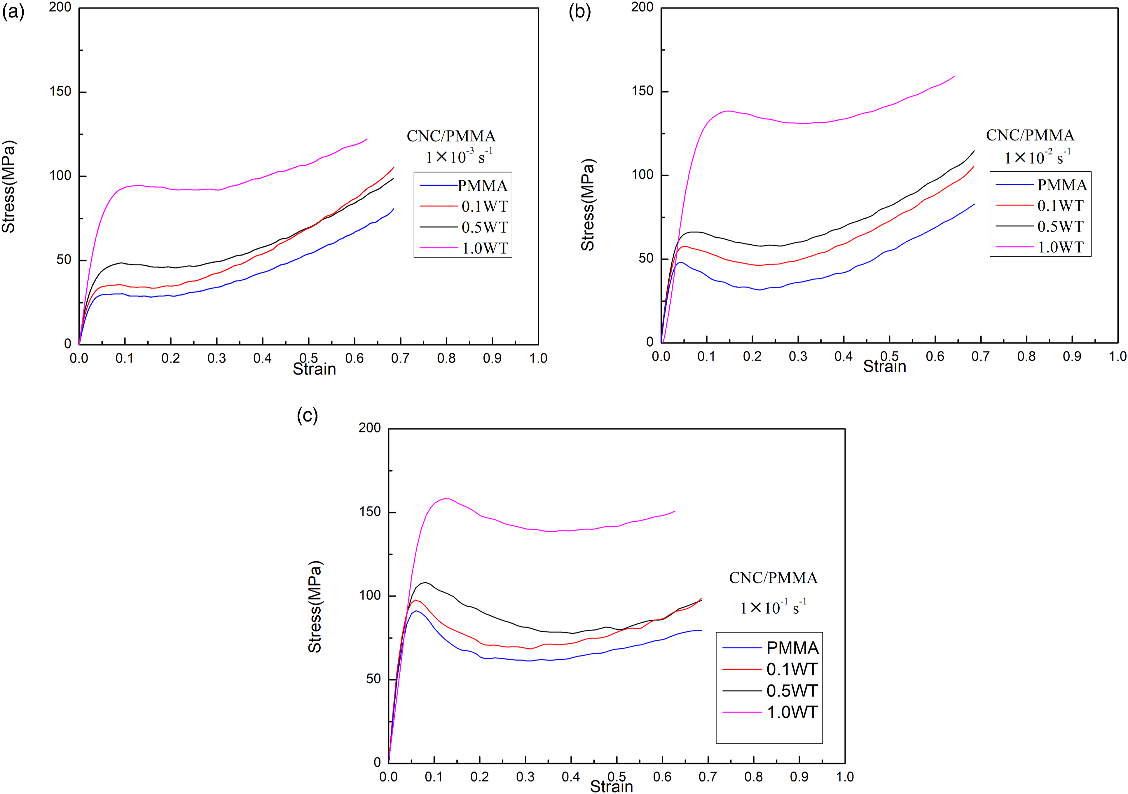


Overall, the results presented in Figures 6, 7, 8, and 9 show that all of the composite specimens (both CNC-based and CNF-based) undergo initial work hardening in the early deformation stage (after the yield point). Furthermore, for both materials, the mechanical response (i.e. the flow stress) improves with an increasing nanocellulose concentration. Finally, the CNF/PMMA composites provide a better mechanical response than their CNC/PMMA counterparts. The superior performance of the CNF/PMMA composites is once again attributed to the greater length and aspect ratio of the CNFs, which enhance the toughness and ductility of the composite material.
Conclusion
CNC and CNF nanomaterials have been prepared from rice straw and mixed with PMMA to produce CNC/PMMA and CNF/PMMA composites with CNC/CNF additions of 0.1–1.0 wt%. The TEM observations have shown that the CNC nanomaterials have an aspect ratio of around 30, while the CNFs have a much larger aspect ratio of approximately 100. For both nanocomposites, the nanocellulose materials are uniformly distributed in the PMMA matrix with a network-like structure. In ball-on-disk wear tests performed against a chrome steel ball counterbody, the optimal wear performance (i.e. the lowest wear volume and coefficient of friction) is obtained by the CNF/PMMA composite with the minimum CNF addition of 0.1 wt%. By contrast, in impact tests performed under quasi-static and dynamic strain rates, the maximum flow stress is obtained from the CNF/PMMA composite with the maximum CNF addition of 1 wt%. The superior tribological and mechanical performance of the CNF/PMMA composites can be attributed to the longer length and aspect ratio of the CNFs, which increase the entanglement of the CNFs with the polymer matrix and improve the toughness and strength of the composite material as a result. The future work will be investigated the other addition in the polymer matrix ex. nano-particle on PMMA or PLA etc.
Footnotes
Acknowledgements
The authors gratefully acknowledge the use of EM000600 of MOST 110-2731-M-006-001 belonging to the Core Facility Center of National Cheng Kung University.
Declaration of conflicting interests
The author(s) declared no potential conflicts of interest with respect to the research, authorship, and/or publication of this article.
Funding
The author(s) disclosed receipt of the following financial support for the research, authorship, and/or publication of this article: This study was supported by the Ministry of Science and Technology (MOST) of Taiwan under Project No. MOST 110- 2628-E-992 -002, MOST 110-2221-E-006-150, MOST 111-2221-E-006-145, MOST 111-2221-E-006-147-MY2, MOST 111-2221-E-006-133.