
Abstract
An interesting technique for modifying carbon fiber-reinforced polymer matrix composites is through hybridization with carbon nanotubes (CNTs). Carbon nanotubes sheets/carbon fibers offer potential benefits of nanoscale reinforcement to the well-established fibrous composites by creating multiscale hybrid micro-nano composites. In this study, the tensile properties of high tensile strength polyacrylonitrile (PAN)- and high modulus pitch-based carbon fiber-reinforced polymer matrix composites incorporating CNT sheets (CNT-sh/CFs/Ep-H: CNT sheets/carbon fibers/epoxy hybrid composites) were investigated. To fabricate CNT sheets, CNT was vertically grown on a quartz glass plate by chemical vapor deposition. A solid-state drawing and winding technique was applied to transform the vertically aligned CNT array into horizontally aligned CNT sheets. The tensile modulus of the CNT-sh/CFs/Ep-H was higher than that of the composite in the as-received state (CFs/Ep: carbon fibers/epoxy bundle composite). The tensile strength of the CNT-sh/PAN-based CF/Ep-H was lower than that of the PAN-based CF/Ep, whereas the tensile strength of the CNT-sh/pitch-based CF/Ep-H was higher than that of the pitch-based CF/Ep.
Introduction
Carbon fibers are widely used as reinforcements in composite materials because of their high specific strength and modulus.1,2 Today, a number of high strength (>6 GPa) polyacrylonitrile (PAN)- and high modulus (>900 GPa) pitch-based carbon fibers are commercially available. The mechanical behavior of several high strength and high modulus PAN- and pitch-based carbon fibers was recently characterized by Naito et al.3–8
Carbon nanotubes (CNTs), including single-wall CNTs, double-walled CNTs, few-walled CNTs, and multi-walled CNTs (MWCNTs), attract considerable attention and have shown great potential for various applications since their discovery. 9 Carbon nanotubess are desirable fillers that improve the performance of polymers; therefore, the use of CNTs in polymer matrix composites has been a focus for academic researchers and engineers in recent years.10–12 However, a number of challenges must be met before CNTs can be exploited for their envisioned applications to polymers. For example, CNTs are generally entangled and tend to agglomerate in polymers as bundles, ropes, or particles (low volume fraction and dispersion quality), and such randomly oriented discontinuous reinforcements may not deliver the superior properties of CNTs. 13
Recently, great efforts have been undertaken to synthesize millimeter-scale aligned CNT arrays for the production of large-scale CNT structures.14–17 Inoue et al.17,18 reported a rapid, simple, dry, and cost effective method to grow vertically aligned and spinnable MWCNT arrays. With this optimization of vertically aligned CNT growth, horizontally long-aligned CNT sheets in macroscopic lengths have easily been produced. On the basis of a solid-state drawing technique, Zhang et al. 19 created highly oriented, continuous, and freestanding meter-long CNT sheets from a CNT forest. Inoue et al. 20 successfully fabricated large-scale, anisotropic, and well-aligned CNT sheets by stacking and shrinking long-lasting MWCNT webs without binder materials. The aligned CNT sheets could allow the production of high-volume fraction composites with desirable characteristics.21–27
The combination of CNT sheets and carbon fibers offers potential benefits of nanoscale reinforcement to the well-established fibrous composites by creating multiscale hybrid micro-nano composites. However, the mechanical properties of polymer matrix composites reinforced with CNT sheets/carbon fibers have previously not been evaluated.
In the present work, carbon fiber-reinforced polymer matrix composites incorporating CNT sheets (CNT-sh/CFs/Ep-H: CNT sheets/carbon fibers/epoxy hybrid composites) were fabricated via a dry method.17,18 The tensile properties and fracture behavior of CNT-sh/CFs/Ep-H were investigated using epoxy-impregnated bundle composites.
Experimental procedure
Materials
Physical properties of carbon fiber bundles and tensile properties of CNT sheets/carbon fibers/epoxy hybrid composites prepared with different carbon fiber bundles.
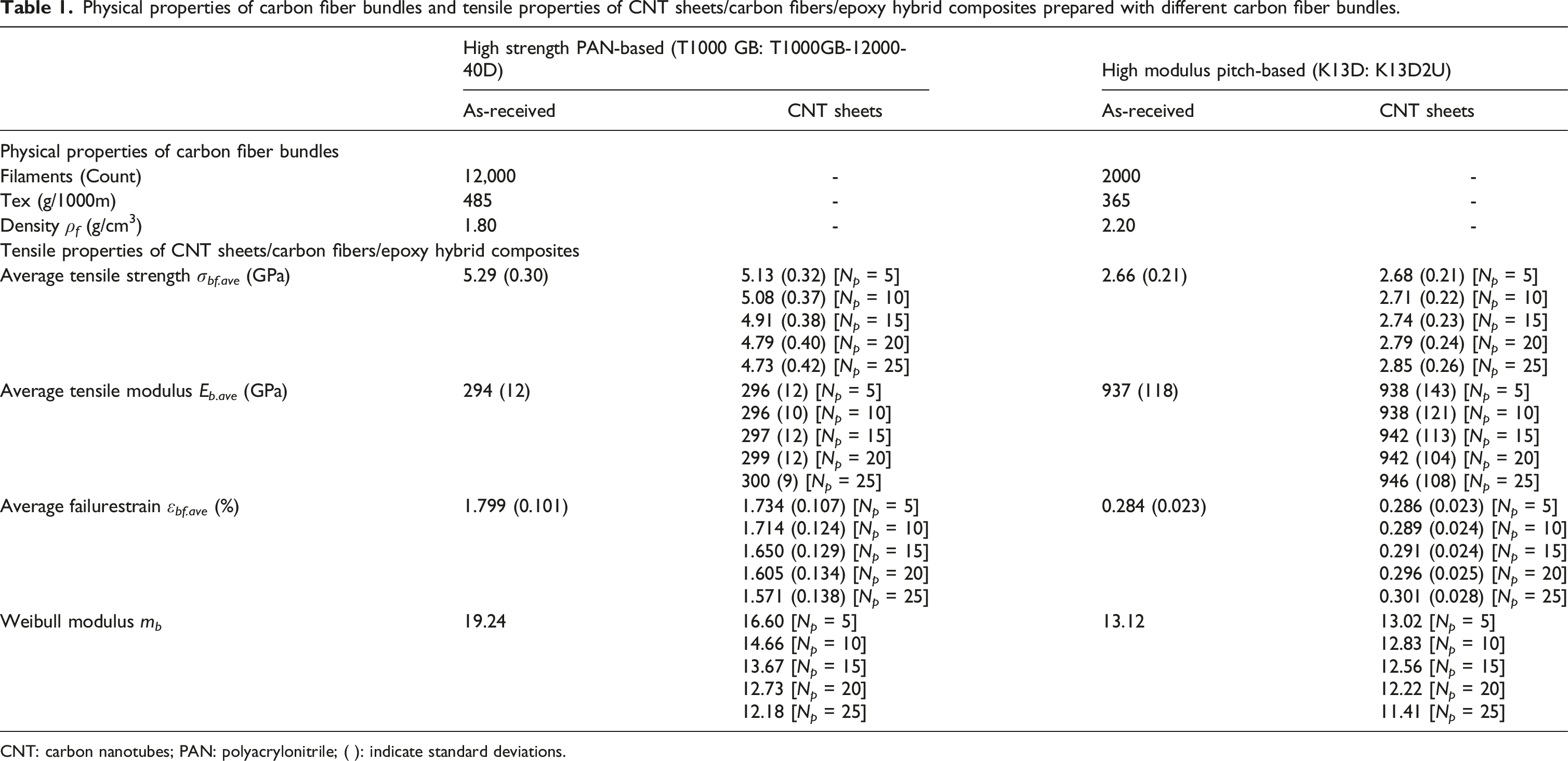
CNT: carbon nanotubes; PAN: polyacrylonitrile; ( ): indicate standard deviations.
The thermoset epoxy solution consisted of a diglycidyl ether of bisphenol A epoxy (JER813, supplied by Mitsubishi Chemical Corp.) and an acid anhydride grade hardener (YH306, supplied by Mitsubishi Chemical Corp.) at a ratio of epoxy:hardener = 100:124 by weight. 28
Preparation of CNT sheets
Multi-walled CNT arrays were synthesized using a conventional thermal chemical vapor deposition (CVD) system. Iron chloride (FeCl2) was used as the precursor for the Fe catalyst. Since catalyst nanoparticles were formed by a vapor-phase reaction between FeCl2 and acetylene at the beginning of the growth process, the substrate did not require pre-deposition with a metal. An unprocessed substrate of quartz or oxidized Si was placed in the growth chamber. Details of the growth method are described in Ref. 17,18. The advantages of this method are its rapid growth rate (>0.1 mm/min) and reaction efficiency with acetylene (>50%). In addition, every array can be drawn for as long as the MWCNTs remain on the substrate. As-grown arrays can be drawn without post-processing.
Vertically aligned MWCNT arrays of ∼1.0 mm in height were grown on quartz substrates using a one-step CVD method with FeCl2 as the catalyst.17,18 Carbon nanotubes sheets can be directly drawn from an MWNT array using the dry-drawing and winding technique, as illustrated in Figure 1. The CNT sheets in this study were prepared with 5, 10, 15, 20, and 25 plies (N
p
) on the basis of the number of winding revolutions. The resulting materials were then examined using scanning electron microscopy (SEM, Quanta 200FEG, Thermo Fisher Scientific) at an operating voltage of 10 kV. Processing of aligned multi-walled carbon nanotubes sheets by dry-drawing and winding.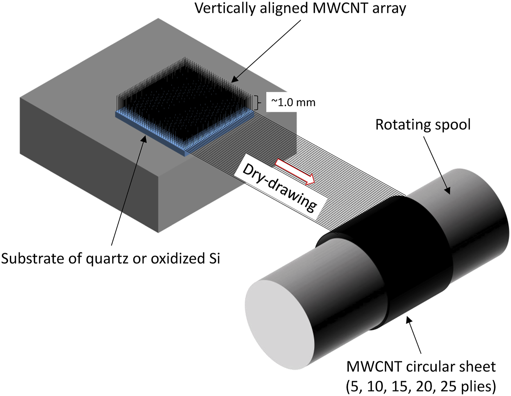
Preparation of epoxy-impregnated bundle composites
The carbon fiber bundles were impregnated using a liquid epoxy solution. The N
p
values of both the CNT-sh/CFs/Ep-H were 5, 10, 15, 20, and 25 plies. To prepare the CNT-sh/CFs/Ep-H, the epoxy-impregnated bundles were covered with the CNT sheets, as illustrated in Figure 2. The composites were cured at 90°C for 3 h followed by 150°C for 12 h (with a heating rate of 3°C/min) to form a rigid bundle composite.
28
Preparation of carbon nanotubes sheets/carbon fibers/epoxy hybrid composite and tensile test specimen.
Tensile test
The bundle composites were trimmed to lengths of approximately 65 mm. Emery paper tabs were bonded to each end of the specimens and a gauge length (L) of 25 mm was used,28–30 as illustrated in Figure 2. The specimens were set up to the testing machine using active gripping systems. Tensile tests of the bundle composites were performed using a universal testing machine (Autograph AG-series, Shimadzu Corporation) with a 5-kN load cell. A crosshead speed of 5 mm/min was applied, primarily for consistency with ref28–30 in order to compare results. The tensile test provides the load (P) as a function of the extension (U
*
) curve until failure. Tensile stress (σ
b
) and tensile strain (ε
b
) were calculated as follows

After testing, the fracture surfaces of the bundle composite specimens were coated using an osmium coater (HPC-1SW, Vacuum Device) and then examined using SEM at an operating voltage of 5 kV.
Results and discussion
Carbon nanotubes sheet
Figure 3 shows the SEM micrographs of the CNT sheets. At a lower magnification, the CNTs appear highly oriented and horizontally aligned in the drawing direction. However, several wavy and entangled CNTs can be observed at a higher magnification. As-grown MWCNTs in this study had an average outer diameter of 40 nm.17,18 SEM micrograph of the surface view of CNT sheets. CNT: carbon nanotubes; SEM: scanning electron microscopy.
Tensile property
Figure 4 shows the tensile stress (σ
b
)-strain (ε
b
) curves for the CNT-sh/CFs/Ep-H. The σ
b
–ε
b
curves for these CFs/Ep (in the as-received state) are also shown in this figure. The strains of the σ
b
–ε
b
curves were offset by 0.25% for PAN-based composites and in 0.05% for pitch-based composites for easy viewing. For all the composites, the stress applied to the specimen was linearly proportional to the strain until failure. The tensile modulus of pitch-based composites was higher than that of PAN-based composites. On the other hand, the tensile strength and failure strain of PAN-based composites were higher than that of pitch-based composites. Tensile stress-strain curves of the CNT sheets/carbon fibers/epoxy hybrid composites (a) T1000 GB PAN-based carbon fiber composite and (b) K13D pitch-based carbon fiber composite. CNT: carbon nanotubes; PAN: polyacrylonitrile.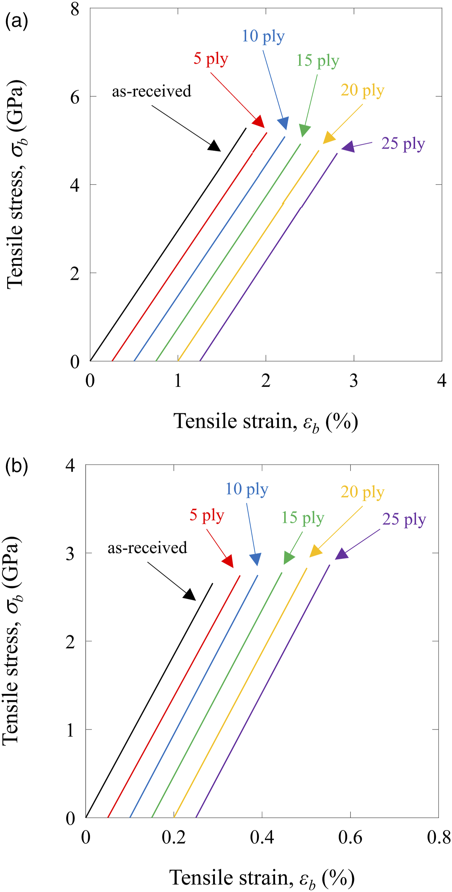
The tensile modulus (E b ) was calculated using a least square method for the straight-line section of the stress–strain curve. The average E b (E b.ave ) values of the CNT-sh/CFs/Ep-H and the as-received CFs/Ep are summarized in Table 1. For both the CNT-sh/CFs/Ep-H, the E b.ave slightly increased with the increase in the CNT sheet content (N p ). Based on equation (1), the addition of highly aligned CNT sheets (including the matrix) does not account for the increase in E b.ave of the CNT-sh/CFs/Ep-H. The stress transferred to the CNT sheets/epoxy composites slightly inferenced by the increase in E b.ave of the CFs/Ep.
The tensile strength (σ
bf
) of the CNT-sh/CFs/Ep-H and the as-received CFs/Ep was calculated as
The ε bf values of CNT sheets/epoxy composites (without carbon fiber) were previously found to be more than 0.35%, 31 which was less than those of the PAN-based CF/Ep but greater than the pitch-based CF/Ep, as shown in Table 1. The ε bf of the CNT sheets/epoxy composites might be affected by the σ bf of the CNT-sh/CFs/Ep-H. For hybrid laminate composites, the fracture of the low elongation composite layers was impeded by the greater ductility of the high elongation composite layers.32,33 Similar results were observed for hybrid composites.34–36
Fracture surface
Typical SEM micrographs of longitudinal views of the tensile fractured surfaces of the CNT-sh/CFs/Ep-H and the as-received CFs/Ep are shown in Figures 5 and 6, respectively. In a previous study, an axial tension failure of unidirectional carbon fiber-reinforced plastic specimens led to the fracture in the transverse direction at several points and was associated with longitudinal splitting of the composite.
37
Similar fracture morphology (longitudinal splitting along the full length of the specimen, resulting in a brush-like fracture surface) was observed for all bundle composite specimens. For both the CNT-sh/CFs/Ep-H, some longitudinal aligned CNTs were observed with the original surface features. The interfacial shear strength between the CNT and matrix was poor. SEM micrographs of the longitudinal views of the tensile fractured surfaces of the CNT sheets/T1000 GB PAN-based carbon fiber/epoxy hybrid composites (a) as-received, (b) 5-ply, (c) 15-ply, and (d) 25-ply. CNT: carbon nanotubes; SEM: scanning electron microscopy; PAN: polyacrylonitrile. Scanning electron microscopy micrographs of longitudinal views of the tensile fractured surfaces of the CNT sheets/K13D pitch-based carbon fiber/epoxy hybrid composites (a) as-received, (b) 5-ply, (c) 15-ply, and (d) 25-ply.

There was a distinct difference in the morphology among the CNT-sh/CFs/Ep-H and the as-received CFs/Ep. The fractured surfaces of the CNT-sh/PAN-based CF/Ep-H showed rough surfaces with some adhesion of resins, whereas the fractured surfaces of the as-received PAN-based CF/Ep showed relatively smooth surfaces with the original fiber surface features. For the CNT-sh/PAN-based CF/Ep-H, the low elongation CNT sheets/epoxy composites began to fail, and the crack mainly propagated into the matrix because of lower energy release of matrix failure. The elongation of net-epoxy was higher than that of the carbon fiber. For the as-received PAN-based CF/Ep, the carbon fibers began to fail, and the crack mainly propagated along the interface between the fiber and matrix because of higher energy release of carbon fiber failure. On the other hand, the fractured surfaces of the CNT-sh/pitch-based CF/Ep-H and as-received pitch-based CF/Ep showed relatively smooth surfaces with the original fiber surface features. The low elongation K13D pitch-based carbon fiber began to fail, and the crack mainly propagated along the interface between the fiber and matrix because of higher energy release of carbon fiber failure.
Weibull modulus
The results shown in Table 1 clearly indicate that there was an appreciable scattering of σ
bf
. The statistical distribution of fiber and composite strengths is usually described by means of the Weibull equation.
38
The two-parameter Weibull distribution is given by


Hence, m b can be obtained by linear regression from a Weibull plot of equation (6).
Figure 7 shows the Weibull plots of the σ
bf
of the CNT-sh/CFs/Ep-H and the as-received CFs/Ep. The m
b
values of the CNT-sh/CFs/Ep-H and the as-received CFs/Ep are summarized in Table 1. The m
b
values of the as-received PAN- and pitch-based CFs/Ep were found to be 19.24 and 13.12, respectively. The m
b
values of the CNT-sh/CFs/Ep-H were 16.60 (N
p
= 5), 14.66 (N
p
= 10), 13.67 (N
p
= 15), 12.73 (N
p
= 20), and 12.18 (N
p
= 25) for the PAN-based composites, and 13.02 (N
p
= 5), 12.83 (N
p
= 10), 12.56 (N
p
= 15), 12.22 (N
p
= 20), and 11.41 (N
p
= 25) for the pitch-based composites. In both cases, the m
b
values were lower than those of the composites in the as-received state. The results clearly show that the addition of highly aligned CNT sheets decreased the m
b
of the tensile strength of PAN- and pitch-based CFs/Ep. Weibull plots of the tensile strength of the carbon nanotubes sheets/carbon fibers/epoxy hybrid composites (a) T1000 GB polyacrylonitrile-based carbon fiber and (b) K13D pitch-based carbon fiber.
The m b (scattering of tensile strength) of the CNT sheets/epoxy composites were thought to be small (large scattering), which might be affected by the m b of the CNT-sh/CFs/Ep-H.
Weibull modulus versus tensile strength
In previous investigations of carbon fibers and carbon fiber polymer composites,4,28–30,39–42 m
b
increased with an increase in the σ
bf.ave
. In addition, a linear relation was found between σ
bf.ave
and m
b
on a log–log scale. In this study, the relationship between σ
bf.ave
and m
b
were also evaluated on a log–log scale. Figure 8 is a representation of m
b
as a function of σ
bf.ave
of the CNT-sh/CFs/Ep-H.29,30 From the viewpoint of the m
b
distribution, it can be seen that m
b
increased with an increase in the σ
bf.ave
of the CNT-sh/PAN-based CF/Ep-H. However, m
b
increased with a decrease in σ
bf.ave
of the CNT-sh/pitch-based CF/Ep-H. In addition, there was an almost linear relation between σ
bf.ave
and m
b
on the log–log scale. The m
b
relates to the strength distribution. These relationships indicate that the σ
bf
distributions of the CNT sheets/epoxy composites strongly depend on the flaw sensitivity and strength values. Weibull modulus of the carbon nanotubes sheets/carbon fibers/epoxy hybrid composites as a function of the average tensile strength.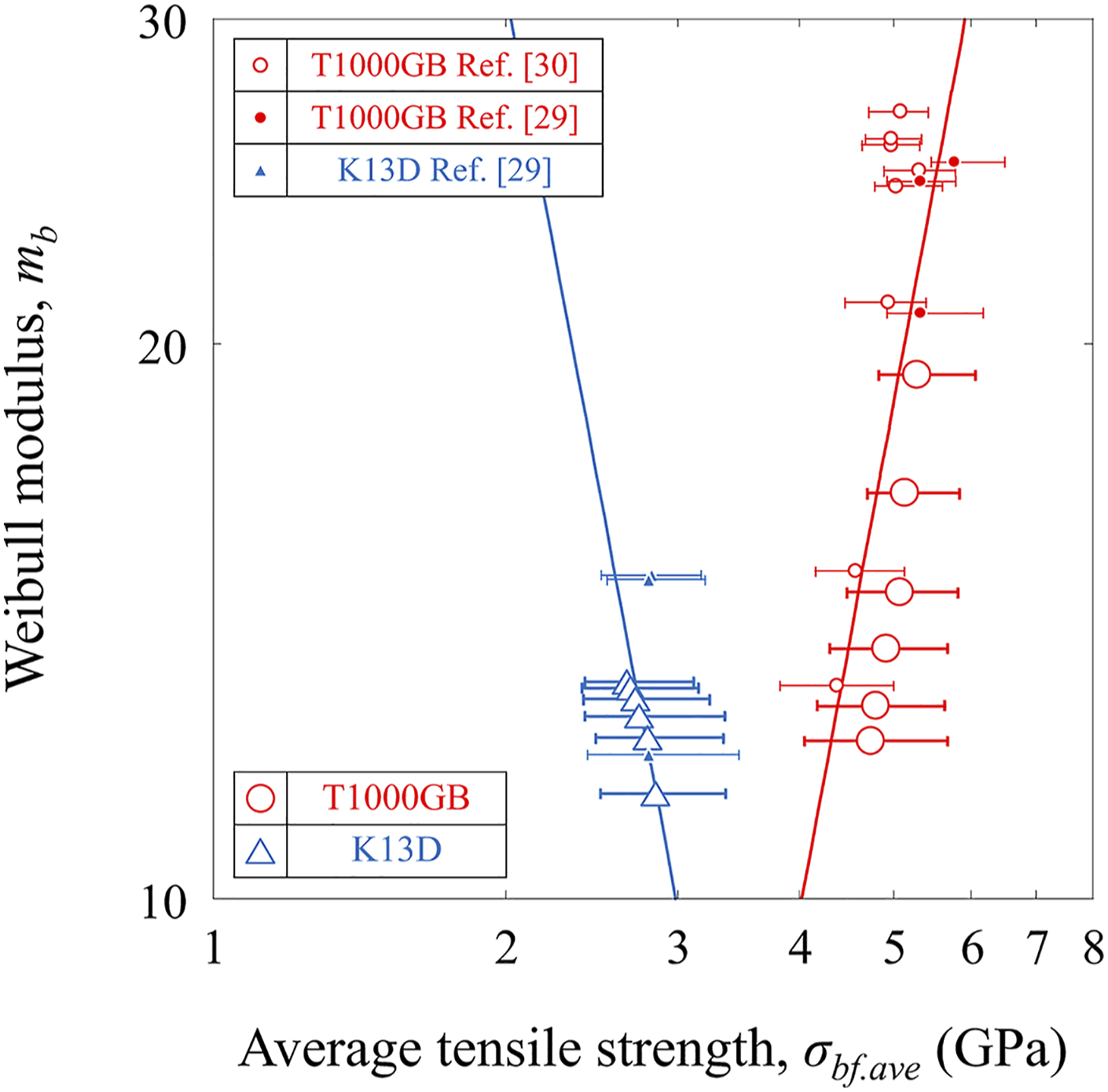
Bundle composites are the smallest-unit load-bearing component in a fiber-reinforced composite. The m b of the tensile strengths of bundle composites (as well as E b , σ bf , and ε bf of the bundle composites) usually depend on that of the fiber-reinforced composites, although the interfacial shear strengths between the fibers and the matrices also depend on E b , σ bf , ε bf , and m b of the fiber-reinforced composites.
Concluding remarks
The tensile properties and fracture behavior of the CNT-sh/CFs/Ep-H were evaluated. The Weibull statistical distributions of the tensile strength of the CNT-sh/CFs/Ep-H were also characterized. The results are briefly summarized. (1) The average tensile modulus of the CNT-sh/CFs/Ep-H slightly increased with the increase in the CNT sheet content (N
p
). The stress transferred to the CNT sheets/epoxy composites slightly inferenced by increasing the tensile modulus of the CFs/Ep. (2) The average tensile strengths of the CNT-sh/PAN-based CF/Ep-H were lower than that of the composites in the as-received state. The average tensile strengths of the CNT-sh/pitch-based CF/Ep-H were higher than that of the composites in the as-received state. This indicates that the hybridization of CNT sheets improves the tensile strength of the high modulus pitch-based CF/Ep, whereas the hybridization of CNT sheets does not improve the tensile strength of the high strength PAN-based CF/Ep. (3) The Weibull modulus of the CNT-sh/CFs/Ep-H was lower than that of the composites in the as-received state. The results clearly show that the addition of highly aligned CNT sheets decreases the Weibull modulus of tensile strength of CFs/Ep.
Footnotes
Authors’ contributions
Kimiyoshi Naito performed research, wrote the manuscript and drew the figures. Chiemi Nagai prepared the test specimens. Keiichi Shirasu prepared the SEM micrographs. Yoshinobu Shimamura prepared the CNT-sheets. Yoku Inoue prepared the CNT. All the authors read and approved the manuscript.
Declaration of conflicting interests
The author(s) declared no potential conflicts of interest with respect to the research, authorship, and/or publication of this article.
Funding
The author(s) received no financial support for the research, authorship, and/or publication of this article.
Data availability
The datasets supporting the conclusions of this article are included within the article.