
Abstract
Carbon nanotubes have extraordinary potential for the modification of reinforcements and matrices in fiber-reinforced polymer composites for enhanced mechanical properties. In this study, 12 fiber-reinforced polymer composites were produced with and without the addition of functionalized multi-wall carbon nanotubes using different stacking sequences of E-glass and carbon fabric reinforcements in simple and hybrid configurations. Carbon nanotubes were incorporated into the fiber-reinforced polymer components prior to composite fabrication by: (i) grafting on reinforcements, and (ii) matrix modification by carbon nanotubes. The grafting of carbon nanotubes exhibited a pronounced tensile behaviour with carbon-rich fiber-reinforced polymers, whereas carbon nanotube-modified matrix showed more enhanced flexural behaviour overall. Around 12% increase in tensile strength was observed when the carbon nanotubes were grafted on to the reinforcements compared to respective pristine composites, while around 70% increase in the flexural strength was noticed as compared to the respective pristine composties when carbon nanotube-modified matrix was used.
Keywords
Introduction
Materials in a composite system are combined in a way to minimize the effect of their deficiencies that enable to make better use of their properties. The use of high strength-to-weight ratios materials in composites allows to achieve complex design features in a variety of applications such as construction, automotive, aircraft, various protective equipment, etc. The composite materials consist of a bulk material called matrix and a reinforcement of some kind and are characterized in general terms by high mechanical, chemical and electrical performance [1]. Following the Second World War, the composites industry has kept growing in full swing making use of new materials and better methodologies for performance enhancement and application expansion. The load transfer ability from fibers to the surrounding matrix and their synergy within a composite plays a significant role in strengthening and toughening it [2]. Fiber and matrix interface is mostly considered as the weakest spot in a composite which causes delamination [3]. Smaller reinforcements at the interface region can prevent a concentrated stress between the fiber and matrix, therefore, increasing the fiber/matrix adhesion [4].
Carbon nanotubes (CNTs) have been acknowledged widely for strengthening the mechanical properties of the composites [5] along with thermal [6] and electrical properties [7]. Zhu et al. [3] found a maximum of 45% improvement in shear strength of glass fiber-reinforced vinyl ester composites by coating a small amount of nanotubes on the midplane ply. There are several ways to accommodate the interaction of the CNTs within the composite materials, which differ with cost, time and resources. The most common method is chemical vapor deposition (CVD) to grow CNTs on reinforcement directly but it requires higher temperatures and time [8–11]. CVD process is also assisted with catalyst-related process such as catalyst coating and annealing which have been associated with a reduction in tensile strength of carbon fibers [12]. Qian et al. [13] have reported that an addition of only 1% of CNTs by weight in a matrix material can raise the stiffness of the composite film by 36–42% and impart 25% improvement in the tensile strength. COOH functionalized multi-walled carbon nanotubes (MWCNTs) grafted on carbon fiber reinforcement along with PAN have been reported with an improved thermal stability up to 850℃ as well as improved UV absorption [14]. Rathore et al. [15] testified an improvement of 11.5% and 32.8% in the flexural strength and flexural modulus of glass fiber-reinforced epoxy composites with the incorporation of 0.1% MWCNTs. Ku-Herrera et al. [16] investigated the interface of glass fibers and functionalized MWCNTs and documented the evidence for the reaction between carboxyl groups of MWCNTs and oxygen containing functional groups of glass fiber coating linked through hydrogen bonding. Eskizeybek et al. [17] experimented the chemical grafting of acid-modified CNTs onto silane functionalized glass fabric to enhance the interfacial properties of multiscale glass fiber/epoxy composites. Lee et al. [18] experimented an alternative route for CNT grafting on carbon fiber and noticed an improvement of 22% in tensile strength of carbon fiber composites grafted with MWCNTs as compared to the corresponding pristine composites. Glass and carbon fiber-reinforced hybrid composites have been researched in a variety of perspectives to reach their maximum potential. Dong and Davies [19] studied the flexural properties and failure modes of different stacking sequences of glass and carbon fiber-reinforced epoxy hybrid composites in a three-point bending configuration. Better flexural strength was reported with samples having glass fiber reinforcement at compressive side and carbon fiber reinforcement at outer surface of specimens.
CNTs can impart their maximum potential in strengthening the composite material if the majority of the load could be transmitted from the matrix to the nanotube [20]. The strength enhancement of CNT reinforced epoxy is dedicated to the interfacial bond strength of CNT/epoxy and total available interfacial area of CNT/epoxy. Such a large interfacial area reduces the interfacial stress concentration and hence facilitates stress transfer from the matrix to MWCNTs. Apart from strengthening and toughening the matrix, if CNT-modified matrix can enhance the interfacial adhesion with fibers then it will reach their maximum potential. In addition to the interfacial stress transfer, the other factors which may actively or passively influence the flexural modulus and strength are: (i) decline in void content due to addition of CNTs into the polymer network [21] and (ii) boosted rigidity because of limited inter-chain slippage attributed to the presence of CNTs [22]. The rate of crack propagation can be limited and deflected by an ideal concentration of CNTs that comes in the way of a crack-tip in a composite. “Pulling out” phenomenon of CNTs from matrix before complete failure has also been reported to enhance the toughness of composites [23] and bridging cracks [13].
In this study, two different methods of CNT integration in composites were experimented using different combinations of layering sequences of reinforcements and compared with their corresponding pristine composites. Previously, CNTs integration methods have been studied individually for the improvement of mechanical properties of fiber-reinforced composites consisting of specific types of reinforcement but its usage has not been investigated for multi-layered hybrid composites, and comparison of integration methods.
Experimental work
Materials
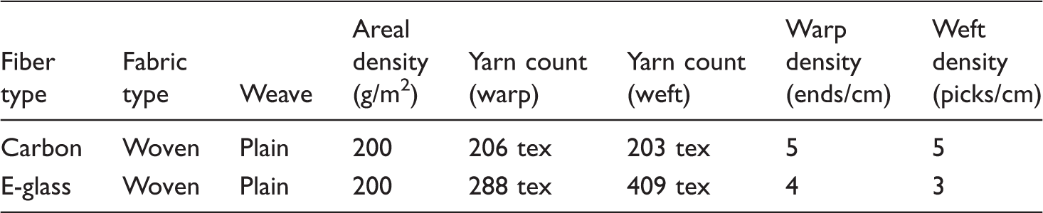
Specifications of reinforcements.
DURATEK 1000 epoxy resin system, supplied by Duratek, Turkey, was used as matrix. It is suitable for open mold lamination processes, fabrication of small parts, and quick production cycles. DTE 1000 + DTS 1100 resin system shows 1.10 ± 0.05 g/cm3 density, 950 ± 100 mPas viscosity and 40 ± 5 min pot life at room temperature [24]. Functionalized (carboxylic group) MWCNTs were supplied by Cheap Tubes Inc., USA. The average outer diameter of MWCNTs was 30–50 nm with an average length of 10–20 µm and the carboxylic content of the MWCNTs was 0.73% (by weight). Polyacrylonitrile (PAN) fibers were composed of a polyacrylonitrile copolymer containing 6–8 wt.% vinyl acetate [P(AN-co-VAc)] with an average molecular weight of 120,000–140,000 g/mol and were supplied by Aksa Acrylic Chemical Industry Inc., Turkey. Dimethylformamide (DMF) with a purity and density of 98% and 0.944 g/ml, respectively, was supplied by MERCK, Turkey.
In the first approach, MWCNTs-grafted reinforcements were prepared by spraying an evenly distributed mist of MWCNT/PAN solution on reinforcements followed by a thermal treatment for stabilization prior to composite fabrication. It has been reported that PAN shows improved interaction with functionalized CNTs and results in chemical bonding with the functional groups of MWCNTs and reinforcements [25].
In the second approach to incorporate CNTs in the FRP composites, CNT-modified resin was prepared by dispersing functionalized MWCNTs in epoxy resin by sonication process. Functionalized CNTs have been attributed to enhanced interfacial properties due to the chemical bonding at the CNT/epoxy interfaces, thus supporting the mechanical properties of FRPs [26].
Fabrication of composites
Twelve FRP composites (dimensions 30 cm × 40 cm) were produced in the configurations presented in Figure 1. First set of composites was manufactured without CNTs in four different stacking arrangements of E-glass and carbon fiber reinforcements as illustrated in Figure 1(a). Same stacking arrangements were repeated with the addition of MWCNTs by two different approaches as illustrated in Figure 1(b) and (c). Detailed explanation of manufacturing process is explained in the next section.
Stacking sequences of FRP composites by three different approaches: (a) illustration of pristine composites without CNTs; (b) illustration of composites with CNTs-grafted reinforcements; and (c) illustration of composites with CNTs-modified matrix. FRP: fiber-reinforced polymer; CNTs: carbon nanotubes.
Figure 2 shows the stepwise preparation of pristine (without MWCNTs) FRP composites as illustrated in Figure 1(a); 37 parts (by weight) of hardener were mixed in the 100 parts of resin. The resin was mixed and applied to reinforcements by hand lay-up so that the reinforcements were completely surrounded by the resin. The impregnated reinforcement stacking was vacuum bagged and cured under vacuum for 48 h at room temperature.
Steps in the fabrication of pristine composites without CNTs. CNTs: carbon nanotubes.
Incorporation of MWCNTs in FRP composites
MWCNTs were incorporated into the FRPs by grafting on to the reinforcements, as shown in Figure 3, and resin modification by MWCNTs, as shown in Figure 4.
Steps in the fabrication of MWCNTs-grafted composites. MWCNTs: multi-walled carbon nanotubes. Steps in the fabrication of composites with MWCNTs dispersed matrix. MWCNTs: multi-walled carbon nanotubes.

CNT grafting on reinforcements
Grafting of MWCNTs was carried by spraying an evenly distributed mist of MWCNT/PAN solution on reinforcements followed by a stabilization thermal treatment as shown in Figure 3. MWCNT/polyacrylonitrile (PAN) solution was prepared by mixing 0.3% (by weight) PAN fibers in DMF; 0.3% (by weight) functionalized MWCNTs were dispersed in PAN/DMF suspension through sonication in a soundproof box. Hielscher UP 400 S 400 W equipped with H3 sonotrode having a tip diameter of 3 mm was used for sonication of the CNT/PAN dispersion in DMF. Sonication was carried for 60 min in two parts with 50% amplitude and 0.5 cycles/s to prepare the dispersion.
Each reinforcement layer was clamped in an iron frame prior to grafting for dimensional stability. Using a low-pressure spray gun (0.08 mm nozzle), 10 ml CNT/PAN dispersion was sprayed on each side of the reinforcement that makes 20 ml for both sides and 60 ml for each composite panel. Special care was taken to ensure even distribution of the CNT/PAN dispersion on the surface of reinforcements. The spray-coated reinforcements were subjected to a thermal treatment for 180 min at 250℃ to stabilize the PAN. After stabilization, the reinforcements were stacked in the configurations shown in Figure 1 and FRP composites were produced by fabrication method presented in Figure 2.
CNT-modified resin
Figure 4 shows steps in the fabrication of composites with MWCNTs dispersed matrix; 184 mg (equivalent to 0.3% MWCNT for 60 ml of MWCNT/PAN dispersion used for grafting) of MWCNTs were dispersed in 237 g of resin by sonication for 60 min in two parts with 50% amplitude and 0.5 cycles/s with H3 sonotrode in a sound proof box; 63 g of fast curing hardener was added to the resin after sonication and mixed thoroughly.
The stacked reinforcements as illustrated in Figure 1 were impregnated with CNT-modified resin by hand layup followed by curing under vacuum as explained in Figure 2.
Mechanical characterization
Dimensions of test specimens.

Tensile test
Five FRP specimens of each FRP composite were subjected to tensile test and the ASTM standard D-3039 testing procedure was followed [27]. The tensile tests were performed on the universal testing machine AG-IS 50 KN made by SHIMADZU. Supporting tabs were attached to tensile specimens, as shown in Figure 5(a) and (c), to avoid failure at the grips during the test and were obtained from the same composite panel. The strain was recorded by an extensometer camera. All the specimens were subjected to tensile loading at a rate of 6 mm/min as illustrated in Figure 5(b).
(a) Specimen for the tensile test; (b) tensile test configuration; and (c) fracture of a tensile specimen.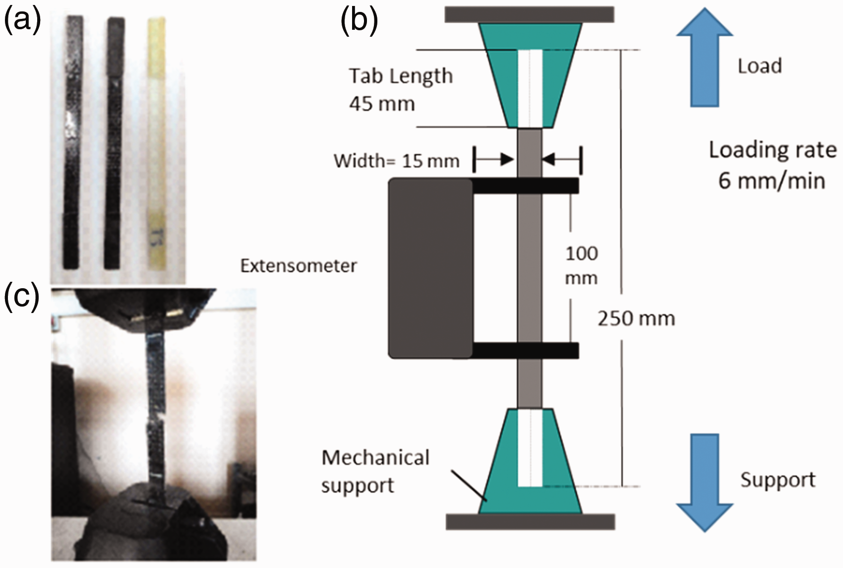
Load–displacement data were recorded for each test event and the tensile strength, the strain, and the elastic modulus were obtained by using equations (1) and (2).


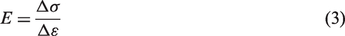
The modulus of elasticity E was computed using equation (3) within the strain range of 0% to 0.3%.
Flexural strength
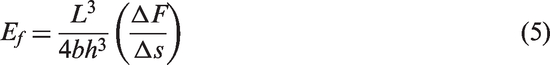
Five specimens of each FRP composite panel were subjected to flexural test in a three-point bending configuration according to ISO 14125 standard [28]. Testing specimens are presented in Figure 6(a). Universal testing machine AG-IS 50 KN made by SHIMADZU was used for three-point bending test according to the assembly illustrated in Figure 6(b) and (c). Specimens were subjected to transverse loading at a rate of 5 mm/min. The load–displacement data were recorded for all the three-point bending test events. Flexural strength was calculated using equation (4) and flexural modulus was calculated, along with the linear region of the load versus displacement curve, using equation (5).
(a) Specimen for the flexural test (three-point bending); (b) three-point bending testing configuration; and (c) fracture of a three-point bending specimen.

Results and discussion
Tensile strength comparison
The tensile behaviours of the specimens against each category are shown as stress versus strain curves in Figure 7. Overall specimens experienced a linear and brittle behaviour up to the failure point. CCC composites exhibited most superior loading behaviour as compared to the other stacking arrangements due to the presence of 100% carbon fiber reinforcements. A significantly enhanced loading behaviour with the incorporation of MWCNTs was also noticed where the CNT-grafted composites showed a tensile strength improvement up to 17% and CNT-modified resin composites showed 12% improved results, Figure 7(a).
Stress vs. strain curves for the tensile loading of: (a) CCC composites; (b) CGC composites; (c) GCG composites; and (d) GGG composites.
Second stacking arrangement of CGC composites specimen exhibited a relatively lower tensile performance as compared to the CCC composites due to the replacement of mid-plane carbon fabric reinforcement with the glass fabric, Figure 7(b). The strain to failure of CGC composites was higher as compared to the CCC composites which can be dedicated to the higher strain to rupture property of glass fabric mid-plane reinforcement. The specimens with CNT-modified resin showed around 15% pronounced ultimate tensile strength, whereas the CNT-grafted specimen revealed around 6% decline in ultimate tensile strength values; however, strain to failure was increased up to 12% with CNT grafting as compared to the pristine composite specimen.
GCG composites exhibited relatively less stiffness than the corresponding CCC and CGC composites due to the presence of higher glass fabric content, Figure 7(c). Strain to failure was similar to the CGC specimens but considerably less as compared to the GGG composite which is evident due to the presence of higher percentage of carbon fiber reinforcements as explained in similar study by Haery et al. [29]. GCG composites also showed lesser ultimate tensile strength than CCC and CGC composites which can be dedicated to the presence of higher glass fabric content replacing carbon fiber. There was a negligible difference in the maximum tensile loading capacity of pristine GCG composites and respective CNT-grafted specimens. The specimens with CNT-modified resin were able to improve the maximum loading capacity up to 19% as compared to the pristine composites.
GGG stacking arrangement accounted for the least tensile strength as compared to the other stacking arrangements; however, these specimens showed the highest strain to failure as shown in Figure 7(d). The addition of MWCNTs did not show any noticeable tensile improvement with both CNT integration approaches. Besides, a 12% drop in the ultimate tensile strength was observed in case of the CNT-grafted reinforcements. Eskizeybek et al. [17] have described the decline in the ultimate tensile strength of CNT-grafted GFRP in his research as a possible result of degradation of glass fiber reinforcement during the thermal treatment in grafting process [17].
Macrographs of the fractured region in tensile test specimen can be seen in Figure 8. Most of the fractures occurred across the width of the specimen with a very low angle as indicated by the arrows in the figures. Close monitoring of these points show crazing which is caused by the concentration of stresses and the moment at which stress concentration overcame the threshold of the material, failure initiated at concerned regions. Thereafter, failure spread along the width of the specimen as the load-bearing area decreased. Pristine CCC and CGC specimen reached failure with a limited matrix shear boundary across the width as shown in Figure 8(a) and (d). The addition of MWCNTs featured a load-bridging characteristic to the composites; therefore, widely distributed rupture points can be seen in case of grafted reinforcements and MWCNTs-modified resin composite specimens for CCC and CGC arrangements.
Macrographs of fractured tensile specimens.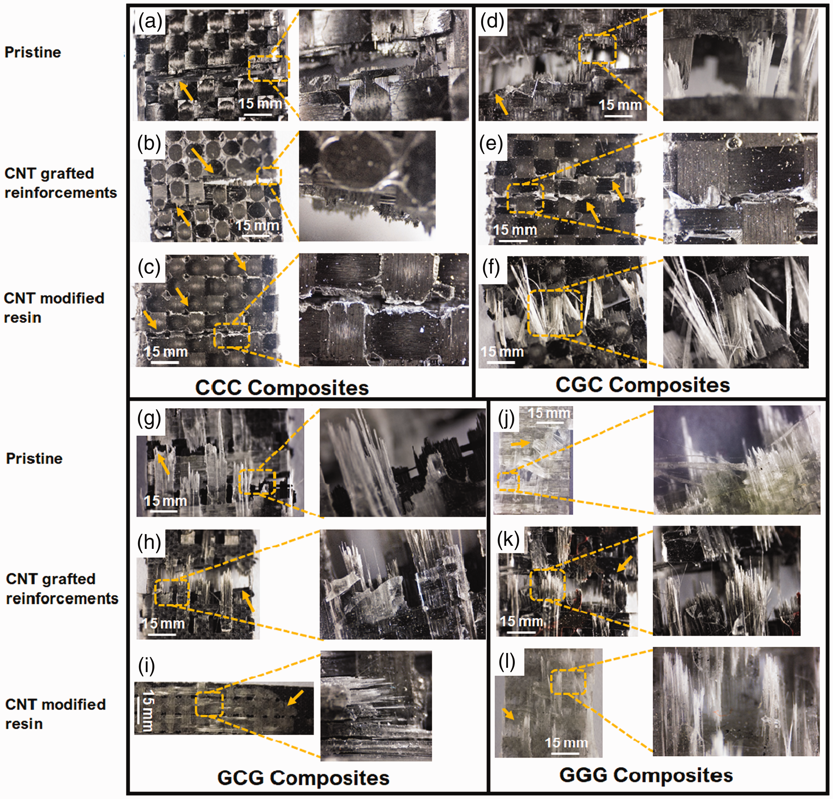
In parallel, glass fiber showed less brittle behaviour before the failure which resulted in some quantity of fibers to pull out from the matrix, Figure 8(d), (f), (g), (j) and (k). The longitudinal split and cracking of glass fiber reinforcements in hybrid composites indicate that majority of the load bearing was dedicated to carbon fiber until failure which has also been concluded in a related literature by Dong and Davies [19]. In case of GCG and GGG composites, a mixed failure phenomenon was observed showing delamination along with the transverse and longitudinal cracking as shown in Figure 8(g), (h), (i), (j), (k) and (l). A promising explanation of this effect can be the difference between strain to rupture ratio of carbon and E-glass reinforcements. Delamination occurred more frequently in CGC stacking arrangement as compared to others. Interestingly, fracture occurred mostly in the non-grafted regions in CNT-grafted GCG and GGG composites as shown in Figure 8(h) and (k). These non-grafted regions were below the corresponding wefts, and therefore mostly remained untreated which have acted as weaker stress points. Figure 8(j) and (l) shows an angular fracture path indicating a shear crack. While applying tensile load on the specimen, stresses were transversely induced along the fiber edges which are mostly random in nature due to which high-stress concentration areas were created. Although, stresses induced in these areas were in the allowable stress limit but they were large enough to rupture the matrix. The angled fracture shown in Figure 8(j) and (l) is actually the path taken by these stresses, along with the fiber edges, throughout the width of the coupon. The research contributed by Gouda et al. [30] explains the fracture mechanism of glass-carbon fiber-reinforced hybrid composites in which the flat and smoothly fractured matrix surfaces have been associated with brittle breaking behaviour and the debonding of fiber–matrix is related with the fiber pull outs which were more in case of glass fiber [30].
Comparison of the mean values of ultimate tensile strength and elastic modulus against each category is shown in Figure 9(a) and (b). Mean values and standard deviations of results were calculated and plotted in the graphs for analysis. The results from tensile strength and elastic modulus of CGC, GCG and GGG show same order (CNT modified resin > pristine > CNT-grafted RF). However, the order is different for CCC laminates (CNT grafted RF > CNT-modified resin > Pristine) which can be explained due to better direct interaction of CNTs with carbon fiber reinforcements as compared to the E-glass fiber in other laminate sequences. The highest elastic modulus value for CCC laminate sequence is also attributed to 100% carbon fiber reinforcements as compared to CGC, GCG and GGG laminates.
(a) Tensile strength comparison; and (b) elastic modulus comparison.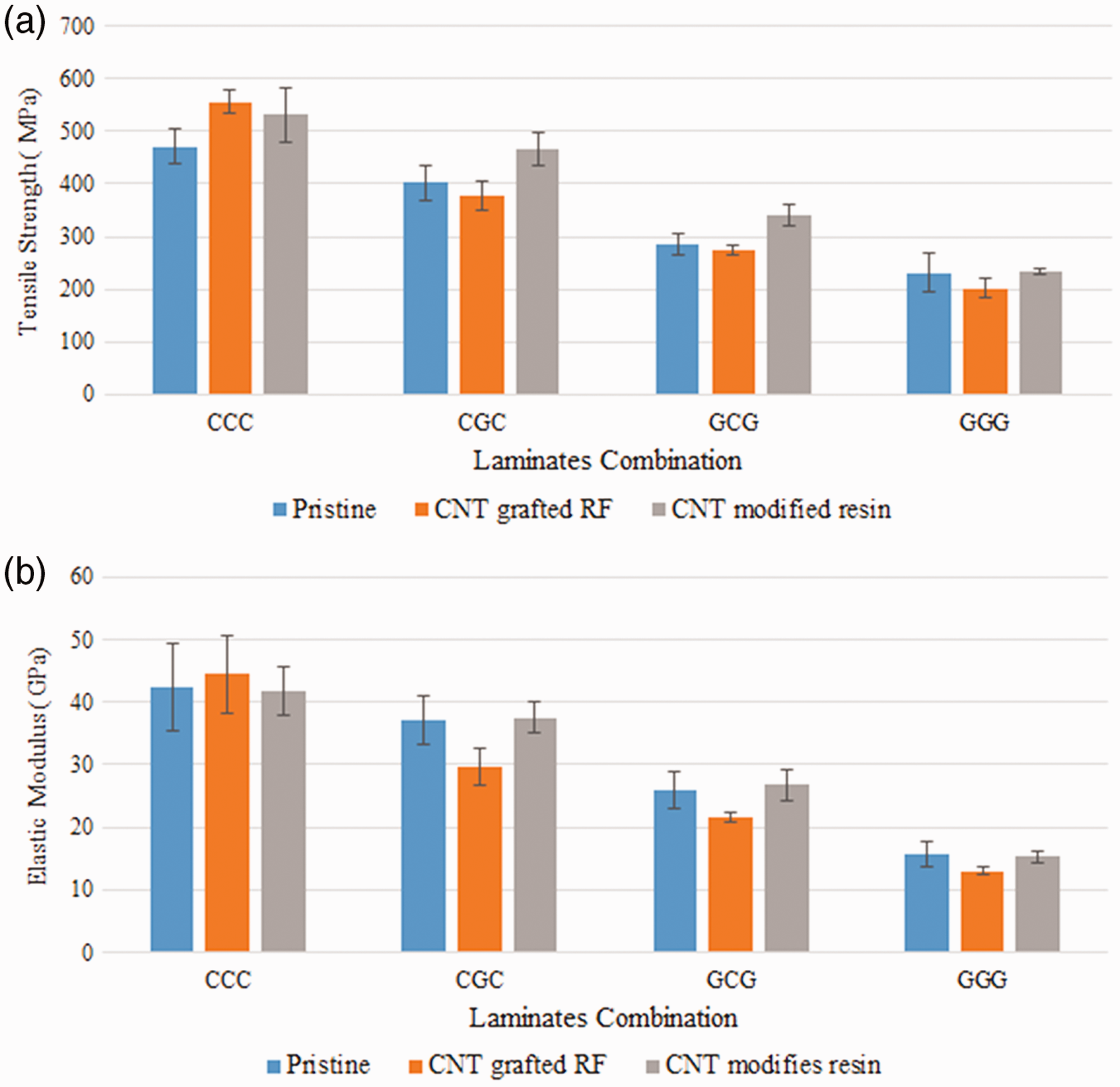
Pristine CCC and CNTs-integrated CCC composites showed the highest tensile strength as compared to other stacking arrangements which were duly maintained by the presence of higher number of carbon fiber reinforcements. GGG composites showed the lowest tensile properties with and without CNTs integration since E-glass has relatively lower tensile strength than the carbon fiber. The improvement in the strength with the addition of CNTs can be associated with the branched networking of the nanofillers which were able to reduce the immediate cracking and stress concentration avoiding delamination. Close monitoring of the fractured specimen will be able to give more knowledge about the breaking mechanism of the specimens. The elastic modulus of the pristine and CNT-modified epoxy composites exhibited similar behaviour; however, the elastic modulus of specimen consisting of CNT-grafted glass fiber reinforcements in CGC, GCG, and GGG composites showed a decline up to 20% attributed to higher strain values at failure for these composites. A similar drop in tensile behaviour by CNT-grafted glass fiber-reinforced composites has been documented in literature by Eskizeybek et al. [17].
Flexural strength comparison
The bending behaviours of the specimens against three-point bending test for each category are shown in Figure 10. Different failure behaviours were observed during flexural loading before and after primary load fall which have been indicated by the arrows in the figure. In the earlier study by Sánchez et al. [31], such curves can be classified into two major parts: the linear deformation up to the maximum loading and the other one referring to the gradual decreasing load fall steps after the maximum loading capacity. It can be explained by the presence of out-of-plane fiber breakage while loading and accompanied by step increases in strength corresponding to the matrix cracking and local delamination. CCC composites showed the highest loading capacity which was further enhanced by the presence of MWCNTs, Figure 10(a). The loading capacity was increased up to 5% by the CNT-grafted reinforcements and 17% by CNT-modified resin specimens. The increase in loading capacity also came out with higher stiffness and lower crosshead displacement before the fracture point as compared to the pristine composite which can be explained by the branched networks of CNTs surrounding the reinforcement and spread in the matrix resulting in higher cohesive forces.
Load vs. displacement plots for three-point bending tests for: (a) CCC composites; (b) CGC composites; (c) GCG composites; and (d) GGG composites.
In case of CGC pristine composites, the maximum loading capacity was found around 35% lower than the pristine CCC composites, Figure 10(b). CNT grafting on reinforcements enhanced the maximum loading capacity up to 23%, whereas resin modification with CNTs showed a pronounced maximum loading around 58% as compared to the pristine CGC composite. CNT-grafted CCC, CGC and GCG specimens showed an increased resistance to applied load followed by the primary load fall. Higher secondary load fall values can be seen in Figure 10(a) to (c) as compared to the primary load fall values for CNT-grafted arrangements which indicate better adhesion at the carbon fiber–epoxy interface supported by the grafted CNTs.
Figure 10(c) shows the load versus crosshead displacement curves for GCG stacking arrangement. The maximum loading capacity of the pristine specimen was found 50% and 23% lower as compared to the pristine CCC and CGC stacking arrangements. The gradual decrease in the maximum loading values occurred due to the replacement of carbon fiber reinforcement with the E-glass as explained in similar literature by Elanchezhian et al. [32] and Poyyathappan et al. [33]. CNT-grafted reinforcements increased the maximum loading capacity up to 40%, whereas CNT-modified resin exhibited improvement up to 70% as compared to the pristine GCG composite specimen.
Flexural behaviour of the composites with GGG stacking arrangement is shown in Figure 10(d) in which the pristine category exhibited almost similar behaviour as GCG pristine composites; however, there was a significant enhancement by the addition of MWCNTs with both methods. The maximum loading capacity was increased up to 23% by CNT-grafted reinforcements and 12% by the CNT-modified resin. Rathore et al. [15] has explained such strength improvement as a reason of effective stress transfer from the soft polymer matrix to the stiff MWCNT through the CNT/polymer interface. The strain values before the failure were found to be significantly higher in the case of GCG and GGG stacking arrangements having CNT-modified resin that indicates a higher energy absorption capability of these specimens.
The flexural specimens showed mixed failure approaches including cracking of fiber and matrix on the compressed surface and tensile shearing on the outer surface. The breakage was further followed by delamination of reinforcements in some specimen.
Macrographs of bending specimens reaching failure are shown in Figure 11 against each category and stacking arrangement. The arrows indicate different regions and modes of failure. Pristine composites with CCC and CGC arrangements exhibited regions of delamination and fiber pull out in Figure 11(a) and (d) demonstrating reduced interfacial strength as compared to the MWCNTs-incorporated specimens in Figure 11(b), (c), (e) and (f).
Macrographs of fractured three-point bending test specimens.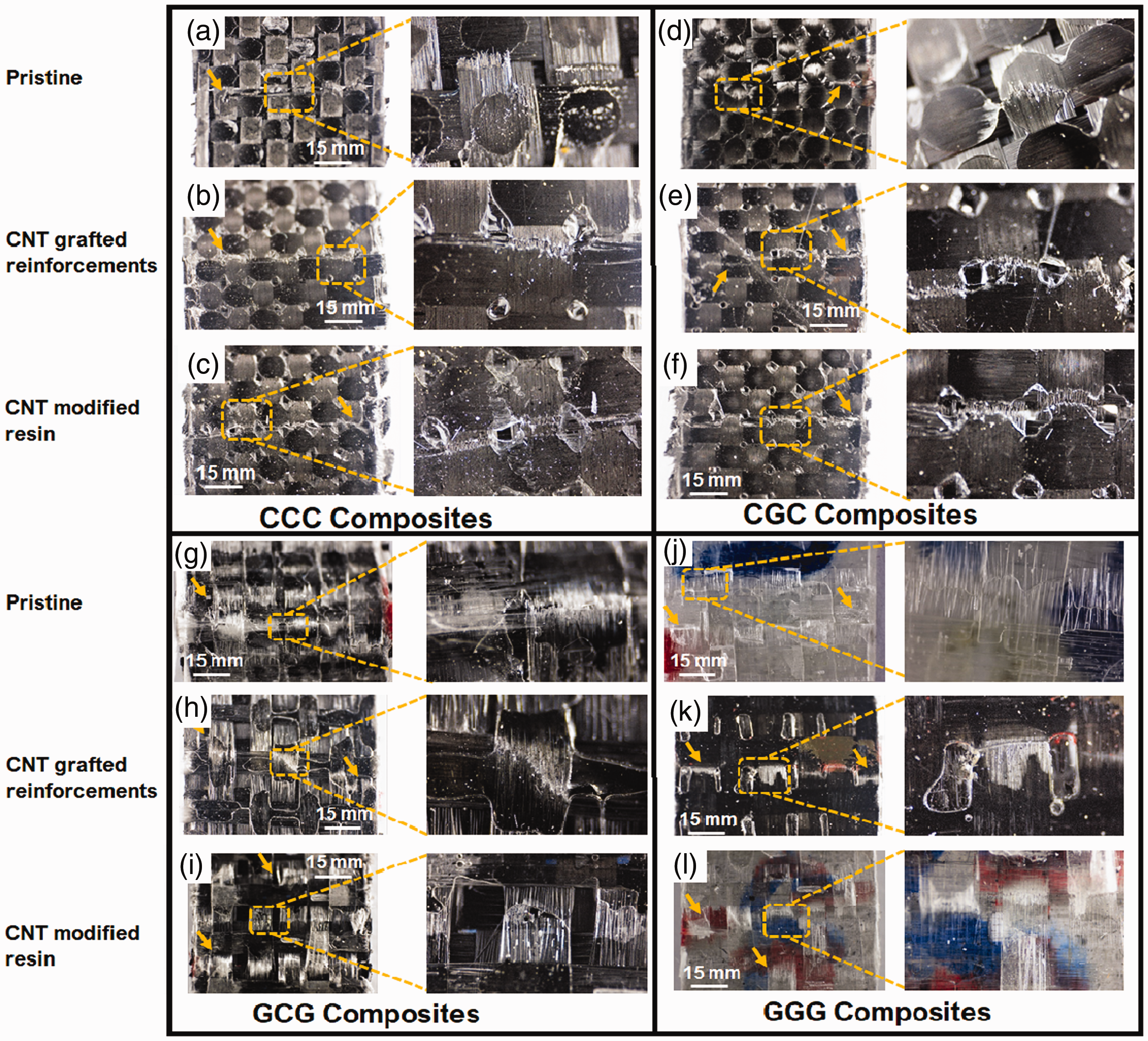
Similar failure mechanism can also be noticed for GCG and GGG pristine composites where delamination was a dominant mode of failure, Figure 11(g) and (j), as compared to the corresponding MWCNTs-integrated arrangements, Figure 11(h), (i), (k) and (l). Yip et al. [34] have related this behaviour to the lesser interfacial strength at glass fiber/epoxy interphase as compared to glass fiber/CNT/epoxy interphase. CGC composites integrated with MWCNTs exhibited signs of well-spread stress distribution shown in Figure 11(h) and (i), which explains the improved flexural loading capacities.
The comparison of mean values of flexural strength and flexural modulus for each category is shown in Figure 12(a) and (b). A decrease in the flexural strength was observed as the percentage of carbon fabric decreased in the composites. There was a significant improvement in the flexural strength of the composites with the addition of the MWCNTs in all stacking sequences which can be dedicated to high aspect ratio and surface area of MWCNTs resulting in an increased interfacial area in fiber/matrix, leading to a higher stress transfer ability across the interfaces. Prusty et al. [35] have explained the reason of well-distributed flexural stresses by CNT-filled FRP composites as the presence of larger interfaces between the fiber and matrix responsible for reducing stress concentrations.
(a) Flexural strength comparison; and (b) flexural modulus comparison.
According to results, composites manufactured with CNT-modified resin exhibited more improvement in the flexural strength than the CNT grafting on reinforcements except for GGG laminates which demonstrated slightly lower flexural strength as compared to CNT-grafted composites but higher than pristine composites. The improvement is attributed to the reduction in microcracking by the MWCNTs in the compact matrix network. The improvement appeared to be noticeably higher in hybrid sandwich stacking arrangements (CGC and GCG). The maximum cross head displacement before cracking was observed in CNT-modified resin GCG composites followed by CNT-modified resin GGG composites. The increased crosshead displacement is attributed primarily to the presence of E-glass fabric, because of its higher strain to rupture characteristic, which was further enhanced by the presence of MWCNTs in the matrix by CNT pull out and crack bridging feature as explained by Qian et al. [13].
CNT-modified resin composites showed a significant increase in the flexural modulus as shown in Figure 12(b). The highest improvement was noticed in CNT-modified resin GCG composites which increased to 37% as compared to the respective pristine composite. Composites consisting of CNT-grafted reinforcements showed a decline in flexural modulus up to 10% as compared to pristine composites in all stacking arrangements. The improved results from three-point bending test show a higher compatibility between functionalized MWCNTs and epoxy resin interaction specially in the case of CGC, GCG, and GGG stacking arrangements in contrast to the CNT integration by grafting on reinforcements. There was no significant difference of flexural modulus between CCC and CGC pair and between GCG and GGG pair, which can be attributed to the same fiber type present at the outer surfaces of the composites in respective pairs.
Conclusion
Two types of CNTs interaction in E-glass and carbon fiber reinforced epoxy composites were studied in this research: (i) grafting MWCNTs directly on reinforcements and (ii) modifying matrix with CNTs; 12 composite samples were manufactured by using two different approaches for CNTs interaction in composites. Two types of mechanical tests were conducted on specimens: tensile and three-point bending test. Macrographs of fractured specimens were examined to understand the breaking behaviour. Results showed that the MWCNTs grafting on carbon reinforcements in CCC composites was able to improve the tensile strength by 12% and flexural strength by 5% showing good grafting compatibility with carbon fiber. CNT grafting on glass fiber could not result in any significant improvement in the tensile strength. CNT-modified matrix showed significant improvements in the flexural properties of the composites which were observed highest in the case of hybrid sandwich composites. Maximum improvement of 70% in flexural strength with respect to pristine composites was observed in the case of GCG stacking sequence. The performance improvement can be related to the matrix strengthening due to the presence of MWCNTs as nanofillers which played an important role in bridging the micro cracks and strengthening the composites. Composite with added MWCNTs showed a load falling in steps after maximum flexural loading which exhibits higher energy absorption feature dominated by the out-of-plane fiber loading.
Footnotes
Declaration of conflicting interests
The author(s) declared no potential conflicts of interest with respect to the research, authorship, and/or publication of this article.
Funding
The author(s) disclosed receipt of the following financial support for the research, authorship, and/or publication of this article: This study was funded and supported by Bilimsel Araştırma Projeleri (BAP), Istanbul Technical University, Turkey against the research project no. 38830.