
Abstract
Fatigue behaviour is an important aspect for consideration while handling glass fiber-reinforced polymer (GFRP) composites. A combination of (0°/90°) and (±45°) plies are gaining practical interest in engineering applications due to their excellent mechanical properties. Properties of individual above-stated plies primarily influence the behaviour of laminates. Fatigue behaviour of on-axis (0°/90°) and off-axis (±45°) fiber orientated woven GFRP laminates was investigated. Tensile and tension-tension fatigue tests were performed on the prepared test coupons according to the ASTM standard. Fatigue test was conducted until failure at maximum applied stress of 90%, 70%, and 50% of the respective ultimate strength. Damage growth was monitored in the term of debond zones by employing the transmission light photography technique. Testing process was recorded by using a digital camera. The results were established in terms of the stress-strain curve, Wöhler curve, debond zones and dynamic stiffness. The fatigue strength of off-axis laminates was much lower than the on-axis laminates. Global damage has occurred in (0°/90°) laminates while (±45°) laminate witnessed localized damage. At higher stress levels, samples were failed at shorter lifespan with aggressive damage; however, on-axis specimens survived with longer fatigue life.
Introduction
Polymer matrix reinforced with glass fiber had gained immense attention in the industrial and scientific fields because of their excellent enhanced properties such as low weight, high stiffness and strength, durability, and high fatigue strength characteristics.1–3 Fiber-reinforced polymer (FRP) composites were broadly used to manufacture load-bearing engineering components such as marine industries, wind turbine blades, aerospace, automation bridge structure, etc., that mostly depends upon ply orientation. One of the most critical failure types of fiber-reinforced composites during their service is fatigue failure. The fatigue damage behaviour of woven laminates has not been as broadly investigated as their UD counterparts. Fatigue damage and its mechanism are influenced by a majority of parameters, which include orientation of woven fiber in weft and warp directions, matrix interface, interface strength and fiber surface defects. 4 Due to the presence of fatigue damage, ability of the material to hold extreme loads reduces, which leads to failure. Ji et al. 5 studied the fatigue life and in-plane fatigue failure of (0°/90°) woven CFRP laminate under constant and variable amplitude loading. Many researchers have shown mechanical behaviour of glass-epoxy composites along with on-axis and off-axis directions in their work.6–10 Zhao et al. 6 investigated the mechanical and failure behaviour of woven glass fiber under on and off-axis loading by acoustic emission and optical observation. Zhuang et al. 11 studied damage behaviour and damage growth with different fiber orientations of woven CFRP laminates subjected to tensile and bending load. They concluded that (0°/90°) laminate exhibited the best tensile and flexural strength, dominated by delamination, and (±45°)laminate had the best energy absorption due to its pseudo-ductile behaviour. In contrast, the tensile and flexural strength decreased drastically compared to laminate (0°/90°). Selezneva et al. 12 studied the damage behaviour of off-axis (±45°) carbon fiber reinforced polymers woven laminates under cyclic loading and observed that fatigued specimens failed after experiencing significant elongation and necking. Bergant et al. 13 studied the static and dynamic mechanical behaviour of 0° and (0/±45) laminate fabricate with different manufacturing processes. Recently Kumar et al. 14 investigated the mechanical properties of (0°/90°) and (±45°) laminate and correlated them with machining parameters. Due to the good mechanical behaviour of (0°/90°) and (±45°) plies laminates, a combination of these two plies is gaining practical interest in engineering applications.7,15 Szabo et al. 16 investigated the mechanical behaviour of woven composites using a multi-scale approach for on-axis, off-axis, and combination of these two orientations.
Progressive material properties degradation, structural disintegration, and stiffness reduction may occur due to damage occurrence like delamination, which causes the final failure of the structures. Therefore a broad study is required to understand the damage behaviour of delamination in laminated composite with different ply angles, which is an essential consideration for the analysis and design of composite structures. Delamination is a matrix-dominated failure mode and mainly occurs in resin-rich interlaminar regions. 17 Generally, matrix-rich regions in woven fiber occurred at the tow cross-over point. As the laminate made up of glass fiber and epoxy is translucent in nature, the growth of fatigue damage (e.g., debond zones and delaminations) is easily noticeable in the gauge area of the test coupons under an illuminated-light background, which can be easily examined by technique commonly known as transmission light photography (TLP). 17
In the fatigue process, hysteresis behaviour of FRP composite made up of thermoset epoxy is associated with damage-induced process. Energy dissipation during cyclic loading is also a parameter that decides the life of a component. Stress-strain hysteresis loops are directly obtained from the stress-strain curve under fatigue processes.15,18 The area of stress-strain loop calculates the total dissipated energy (TDE) per cycle, and variation of the elastic modulus with the cycle number is measured by the slope of hysteresis loop. 19 Energy is dissipated due to the presence of damage, e.g., fiber breakage, fiber bridging, and friction of the unrestrained region in the matrix and matrix/ fiber interface. 20 More Energy dissipation occurs due to the existence of secondary bonds in the polymer. This type of bond produces more frictional force between the polymeric chains because of their viscoelastic nature. 21 Some researchers have studied the evolution of the hysteresis area per cycle.15,18 However, few works have shown the influence of stress levels on that material in terms of dissipated energy.
Various methods such as X-ray radiography, 22 infra-red technique, 23 acoustic emission technique,9,24 and TLP10,25 are used to assess the damage initiation and progression in the materials. Some previous works have been done on in-situ damage development under different loading conditions by SEM technique. However, to the author's knowledge, focused work to in situ fatigue damage development and comparison of on and off-axis laminated composite using the TLP technique are not available. In the present study, TLP technique is employed to study the in-situ damage evolution in on-axis and off-axis laminates under static and dynamic load conditions and compare their behaviour. The outcomes of tests under quasi-static loading are presented in terms of the stress-strain diagram and the TLP image of failed samples. Whereas those tested under dynamic loads have their results presented as Wӧhler curve (S-N diagram), hysteresis increment with number of cycles and dynamic modulus. The influence of stress level on fracture intensity has also been presented.
Experimental procedure
Material and sample fabrication
In the present work, Plain weave E-glass fabrics with a surface weight of 610 grams per meter square (GSM) were used as reinforcement to fabricate the laminate. This fabric was provided by SS polymers Bengaluru, India. Bisphenol-A-based thermosetting epoxy and di-amine-based curing elements of commercial name Araldite LY 556 CS Aradur HY 951 were procured from Huntsman. Epoxy and hardener were mixed in a ratio of 10:1 to form matrix material. The flow time of the matrix was found to be 20 min.
Woven fibers have waviness due to tow cross-over points that cause matrix-rich as well as matrix-deficit regions, creating large debond zones when loaded. This could be easily studied using in-situ transmission light photography when composites are subjected to quasi-static and dynamic loading.
25
Plies with fiber orientation (0°/90°) and (±45°) having dimensions 280 mm × 280 mm were taken from the woven fabric. Plies were wetted by matrix material and placed as per the required stacking sequence. Uncured matrix was applied onto the stacked ply using a soft brush. Later, the stacked wet plies were placed under a press moulding machine with a maximum load capacity of 250 kN. Four 3 mm thick hardened steel brackets were placed around the wet laminate to control their thickness. Figure 1(a) presents the various steps involved in the fabrication process. (a)Sample fabrication process (b) Sample configuration (c) Experimental set-up.
The fiber volume fractions of the fabricated laminates were calculated as per the ASTM D3171-15 standard,
26
and it was found to be approximately 55%. Dimensions of tensile and fatigue specimens were taken as per standard procedure, i.e., ASTM D3039/3039M-17
27
and ASTM D3479/3479M-19
28
Testing procedures
Tensile tests were conducted on the test coupons on Hounsfield H50KS, a computer-controlled UTM with a 50 kN load cell. Tests were conducted as per the standard procedure ASTM D3039/3039M
27
with loading speed of 1 mm.min−1 in displacement control mode. Strains in the loading direction were assessed using a 50 mm extensometer clipped on the leading edge. The test results were noted in terms of ultimate strength (
Fatigue tests were conducted at 90%, 70%, and 50% of their corresponding static strength and monitored for their damage behaviour and respective number of fatigue cycles to failure. Three specimens of both on and off-axis laminate at each maximum applied stress were tested. Optical monitoring was carried out on those samples which were undergoing fatigue tests without an extensometer. In order to study the damage growth in these samples at a macro-scale, the tests were monitored using a digital camera (Nikon D5600 with maximum aperture f/3.5 and focal length of 18-55mm zoom range). The testing setup for this purpose is shown in Figure 1(c).
Result and discussion
Tensile behaviour
Tensile stress-strain response of the tested laminate along with matrix material is presented in Figure 2(a), and their mean values of tensile properties are listed in Table 1. On-axis laminate exhibited much higher ultimate tensile strength (UTS) of approximately 400 MPa, than ±45° laminates that had the UTS of about 105 MPa. While laminates with ±45° fiber orientation had failure strain of 9.81% that dropped to 5.1% when the laminates were reinforced with (0°/90°) fiber. This indicated that tensile properties are shifted from the fiber-dominated one to the fiber-matrix interface
8
and to the area marked by matrix properties due to increased angle between fibers and loading axis. (a)Tensile stress-strain response of tested samples (b) Failure morphologies of samples under tensile loading (i) (0°/90°) laminates (ii) ±45°laminates. Tensile properties of laminates and epoxy. UTS: ultimate tensile strength.

Under tensile loading, fiber and matrix present in the FRP composite were experienced non-progressive and progressive failure, respectively. Figure 2(b) shows the TLP image of failed specimens under tensile loading. Prior to failure, in-plane loading of on-axis laminates observed the maximum fibers involvement, which gave more reinforcement to the laminate. While, with increasing ply angle, the stresses are still in-plane, but the stress state becomes multi-axial.
30
Loading caused matrix cracking in transverse direction of laminates, irrespective of their fiber orientation. These cracks further propagated to form interfacial distortions between fibers and matrix in the weft direction fiber in 0°/90° laminate and also towards both directions (warp and weft) in ±45° laminate. Shear forces are generated in off-axis laminates, resulting in a rapid degradation in their fiber/matrix interface was occurred. In the absence of fiber-matrix interface, the fibers were found to rotate towards the loading direction leading to pseudo-ductile deformation
31
while the basic fracture mode remained brittle in nature, which is shown in Figure 3. (0°/90°) laminates displayed a linear behaviour in their stress-strain curve while ±45° laminates showed linear stress-strain responses followed by nonlinear ones. Laminates reinforced with ±45° fiber orientation witnessed non-linearity in deformation approximately 80% of the failure strain. Similar findings have been found in experimental work performed by Zhao et al.
6
Rotation of fibers in ±45° laminates causing longer elongation in samples.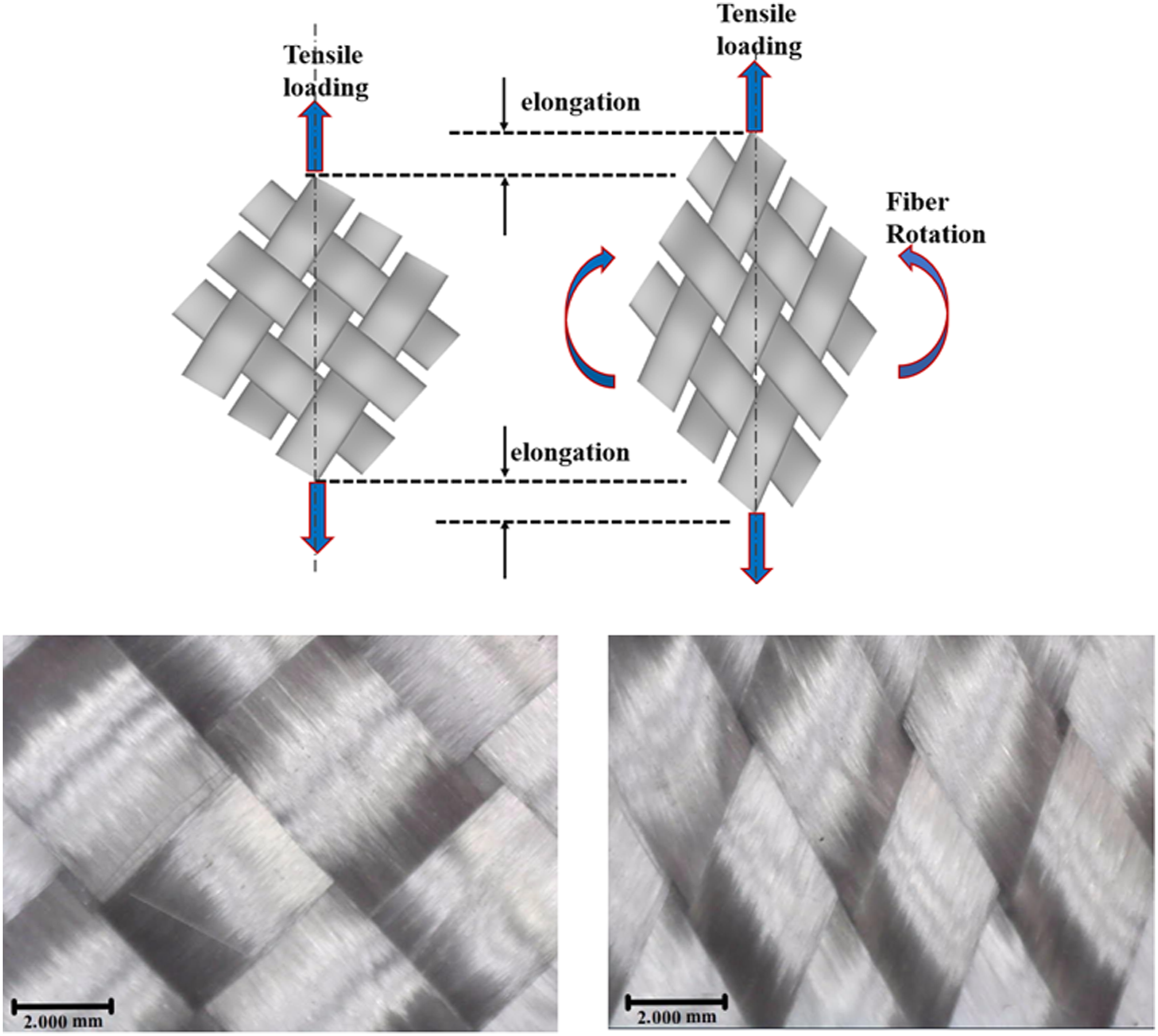
Fatigue behaviour
Wöhler curve in terms of the maximum stress (σmax), normalized stress, and number of cycles to failure is presented in (Figure 4(a) and (b)) on a semi-logarithmic scale. Tests were performed on the specimens until failure at different maximum applied stress of 90%, 70%, and 50% of the respective ultimate strength. One million fatigue cycles were considered as runout number of cycles or load equivalent to 50% of the UTS of the laminates, which was observed as the lowermost applied maximum stress. This graph showed that the fatigue life was improved with the reduction in applied stress levels. Power function in form of (a) Maximum applied stress versus number of cycles to failure (b) Normalized stress versus number of cycles to failure for the tested samples.
Fatigue damage evolution
Failure modes in an FRP laminate, subjected to tension fatigue, remain the same as the one under monotonic tensile loading since both the samples are loaded under tensile force. The damage in the test coupons was initiated with the matrix cracking, transverse to the loading direction, and it was mostly independent of the reinforcing fiber orientation. However, the subsequent damage modes showed their dependence on fiber orientation, which could be explained by a TLP (transmission light photography) image. Figure 5(a) and (b) shows the initial damage development in fatigued on and off-axis samples at different percentages of N
f
cycles. Transmission light photography image of tested samples (a) 0°/90° laminates (b) ±45° laminates.
Unlike UD fiber-laminates, which have matrix cracks on micro-and mesoscale, woven fiber laminates undergo inter-and intra-ply debonding as major damage mode. During the present investigation, these failure patterns were observed mostly due to the formation of matrix-rich and deficit regions at the tow crossover points. In (0°/90°) laminates, cracks generated in the direction transverse to loading gradually propagated to the fiber/matrix interface of the fibers at weft direction. Due to the presence of multiple deflection points, the primary matrix cracks were found to propagate in the intraply resin-deficit zone and led to debonding in the tow crossover point and in the matrix-rich region of the interply zone, resulting in their rupture. From Figure 5(a), one can observe the spatial debond zones formed that spread throughout the sample up to the number of fatigue cycles was reached to the midlife cycle (50% of the final failure cycles). Further rise in the number of cycles increased the area of the debond zone but did not increase the debond counts. Once the debond zones became sufficiently large and support of the adjacent plies loosened, the final rupture of the sample took place. From Figure 5(a), one can observe widespread damage in the 0°/90° fiber laminate, mostly due to the engagement of a large number of 0° fibers, gaining additional strength towards the loading direction.
Moreover, when the fiber angle was ±45°, the debond zone did not spread throughout the sample. Rather, it remained localized and rapid degradation in the fiber-matrix interface led to sufficiently large damage around the free edge, turning it into a site of damage development. The samples witnessed smaller and limited debond zones but had a high number of fiber-matrix interface distortion sites (the dark zones), leading to sliding of fibers at warp and fill/weft directions along loading plane from their respective matrix grooves (Figure 3). This mechanism considerably reduced the cross-sectional area and increased elongation along loading direction, which has also been reported by Seleznev et al. 12 The shape of sample became dumbbell-like shape from rectangular shape, and the specimens failed at a relatively lower number of cycles. Off-axis laminates witnessed high shear stress at the free end of the sample due to the progressive failure behaviour of the fiber-matrix interface.
The presence of fibers in weft direction gives transverse stability to the plies in angle-ply laminates, although they act as defects in (0°/90°) fiber laminates. The interface distortion of weft direction fibers and surrounding materials leads to their displacement in the loading direction. Since these laminates are highly heterogeneous compared to their UD counterparts, the development of uniaxial loading in multi-axial is inevitable. While (0°/90°) laminates offered a better fatigue response than their angle ply counterparts, this behaviour could be further enhanced in the presence of UD fibers rather than in woven ones. Figure 5(a) and (b) shows the image of the samples, respectively, with 0°/90° and ±45° fiber orientations, failing under fatigue loading. During investigation, the fracture morphology of the specimen, which failed under fatigue, was found to be similar to the one which failed under static tensile loading (Figure 2(b)). The only difference was the complete separation of the fractured sample under fatigue loading. This was mostly due to excess ramping of the piston post-failure of the material, which led to a significant number of delaminations and fiber pullouts. However, the samples that survived runout number of cycles did not have significant delamination sites within the samples. Instead, they had a few debond zones or cracks at the free ends of the samples, which has also been reported by Kawai and Taniguchi. 32 Moreover, while all the angles ply laminates failed in the gauge region, the (0°/90°) laminate witnessed failure in the vicinity of the tabs.
Effect of applied maximum stress and fatigue failure morphology
Apart from the fiber orientation, the applied maximum stress also significantly affects the fatigue failure of samples. Figure 6(a) and (b) shows the influence of stress amplitude on the failure morphology of the tested laminates. Glass fibers are stiffer than the adjacent matrix, and upon loading the apparent modulus gap causes considerable strain difference instigating high shear forces in the fiber-matrix interface.
33
Magnitude of the shear force developed on the fiber/matrix interface largely depends upon the stress magnitude; where high shear forces are generated in the fiber/matrix interface when the specimens are loaded at high stresses causing fractures mostly dominated by fiber pullouts. On the contrary, samples loaded at low stresses undergo fiber breakage rather than pullouts, mostly due to low shear stresses acting on the fiber/matrix interfaces. Samples subjected to high-stress amplitude witnessed aggressive damage as compared to the one loaded under low stresses. A plausible explanation could be that at high stresses, large cracks develop in fewer numbers, which require lesser number of cycles to propagate and coalesce. On the other hand, samples loaded under relatively low stress, produce a high number of small cracks. These cracks require a large number of cycles to propagate and the samples experience high fatigue life.
33
Larger cracks that eventually propagate in fewer cycles create a large plastic zone ahead of the advancing cracks. While these advancing cracks propagate in the matrix, they leave behind intact fibers, which bridge the cracks. Further cycling breaks the reinforcing fibers and pullouts appear in the absence of matrix. Fatigue failure morphology (a) 0°/90° laminates (1-at 0.9σmax, 2-0.7σmax, 3-0.5σmax) (b) ±45° laminates.
In this study, 0°/90° samples, tested under tension fatigue, witnessed global delamination, while ±45° samples endured local delamination. The presence of delamination itself signifies presence of a concomitant damage mechanism, such as local delamination and microcracks, around the failed sites. Such discrepancy in the delamination zone was mostly due to the presence of matrix microcracks at the free end of the off-axis laminates. Such matrix microcracks develop in the early fatigue life (as shown in Figure 6(b)). Hence, ply splitting of the laminates subjected to fatigue inevitable.
Stress-strain hysteresis and energy loss
Polymers are viscoelastic materials and undergo significant hysteresis loss when they are subjected to fatigue. Figures 7(a)–(c) and 8(a)–(c)explain the evolution of the stress-strain hysteresis in the samples loaded at 50%, 70%, and 90% of their UTS, respectively, during the fatigue test. From the figures, one can observe that samples, irrespective of ply angle, underwent permanent plastic deformation by accumulating significant permanent damage in terms of matrix deformation, fiber breakage, and debond between tow crossover points. As these failures are mostly irrecoverable in nature, there is a slight chance that upon unloading, the laminate will be able to recover the initial strength and stiffness. Samples subjected to fatigue, attained low strain under respective stresses compared to their monotonic counterparts. This was due to the strain rate-dependent behaviour and has been previously reported.
33
Variation of hysteresis loops under cyclic loading in 0°/90° laminates at (a) 0.9σmax (b) 0.7σmax (c) 0.5σmax of ultimate tensile strength. Variation of hysteresis loops under cyclic loading in ±45° laminates at (a) 0.9σmax (b) 0.7σmax (c) 0.5σmax of ultimate tensile strength.

It is observed that with the increment of stress level and the number of cycles, the hysteresis loop area increased. It could be due to the friction produced between debonded and delaminated surfaces resulting in an increase in energy dissipation. 20 Friction magnitude depends on the damaged area, which becomes higher with the rise of stress level and number of cycles. The amount of the TDE increased significantly with the decreasing fatigue stress level. The TDE for each sample is measured by integrating all individual areas of the hysteresis loop. This phenomenon can be explained by the fact that at lower stress levels, it requires higher number of fatigue cycles to failure and dissipation of additional energy for the samples which are tested. In all the cases, area of the hysteresis loop was increased near the end of the fatigue lifetime, which increased the energy dissipation per cycle.
Another important point in this regard is that on, and off-axis laminates were loaded under different maximum stresses on the basis of their ultimate strength. Hence, generated strains were proportional to the applied load. Fiber orientation was found to have a defining effect on the hysteretic behaviour of the laminates on ±45° laminates. This is mostly due to the fact that properties of these laminates are governed mainly through matrix and fiber-matrix interface. No strain shifting was observed in the 0°/90° laminates during low-stress component of fatigue cycle. It was at the peak of stress that shifting of strain was observed. Moreover, in ±45° laminates, the strain shifting or accumulation of plastic deformation was more pronounced. The reason is the same as discussed in the previous paragraph. It could be explained by the fact that in the 0°/90° laminates, small-scale straining of matrix took place around tough fibers by effective stress transfer. However, as the fiber orientation increased, the matrix micro-cracking changed to large matrix deformation and fiber-matrix distortion, which is by and large considered as precursor to the final failure. The penultimate fatigue cycle had the largest hysteresis area owing to the damage build-up and stiffness degradation. The next section deals with this aspect in detail.
The applied maximum stress has a defining effect on hysteresis loss, which is also evident in Figure 9. Figure 9(a) and (b) showed the magnitude of energy loss per cycle in the (0°/90°) and ±45° samples corresponding to the region bounded within a hysteresis loop (in Figures 7 and 8). One can conclude from Figure 9(a) and (b) hysteresis energy loss depends on the size of the loop. Hysteresis loss gradually increased with increased number of fatigue cycles, but before failure, it rose abruptly. The largest strain energy dissipation by the samples is observed during their final cycle since the samples failed at larger strains. Inadequate laminate stiffness due to the absence of transverse support by adjacent plies, erosion of matrix from resin-rich areas, and weakened fiber/matrix interfaces, the specimen fails to release enormous energy. Among the tested samples, irrespective of their loading stress, (0°/90°) laminate witnessed the most considerable hysteresis loss as compared to ±45° laminates, respectively. This was mostly due to the fact that (0°/90°) laminates were subjected to the highest load while the remaining ones were subjected to comparatively lower stress. Hysteresis loss trend with normalized fatigue life is shown in Figure 9(c) and (d). It can be noticed that at higher stress level in ±45° laminate, rate of hysteresis loss was higher mainly during the stage (N/Nf =0.1–0.98) as compared to (0°/90°) laminates. The stipulated reason could be due to the shifting of load-carrying element to fiber-matrix interface and matrix from fibers when fiber orientation changed to ±45°. Due to the progressive damage behaviour of the matrix, significant expansion of the hysteresis loops occurred with increase in fatigue cycle. (a) Magnitude of hysteresis energy loss per cycle in (0°/90°) samples (b) ±45° samples (c) Hysteresis loss trend with normalized fatigue life for (0°/90°) samples (d) ±45° samples.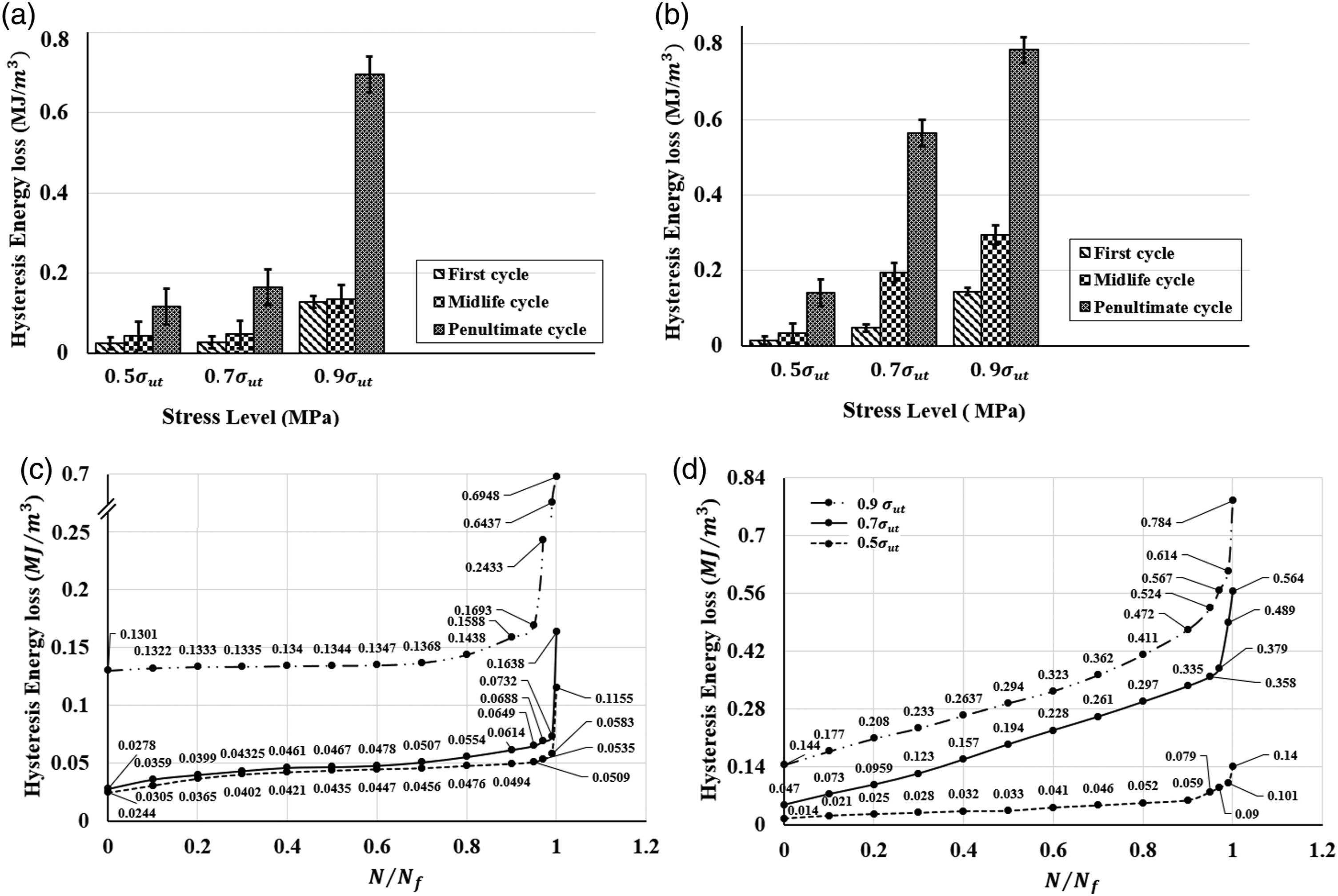
Dynamic modulus
Upon cyclic loading, slop of the axis of the stress-strain hysteresis loop decrease, which indicates the loss of dynamic modulus of specimen. The evolution of dynamic modulus versus the normalized fatigue cycles is shown in Figure 10. On-axis laminates showed the highest dynamic modulus when tested at maximum stress, i.e., 90% of UTS, which dropped upon decreasing applied stress. During the first stage, which accounted for cycle ratio (N/Nf) is approximately 0.05–0.1, the dynamic modulus rapidly decreased due to multiple cracks formation. (0°/90°) laminates showed a sharp drop compared to the (±45°) laminates, because the presence of weft direction fiber orthogonal to the loading direction provided increased number of debond cracks that were mostly absent in (±45°) laminates. Variation of dynamic modulus versus normalized number of cycles at different stress levels.
In the second stage (N/Nf =0.1–0.98), modulus decreased gradually as the fatigue cycles increased. The modulus has almost a linear relationship with the cycle ratio and a significant part of the fatigue life pertains to the second stage. During this stage, crack growth is accommodated in terms of count and length and interply delamination i.e. fatigue crack propagation in other planes, leading to a gradual modulus decay of the specimens. Furthermore, saturation in the matrix crack was attained at the end of second stage. The laminates quickly entered the third stage of modulus drop after saturation in the matrix crack, which lasted until the final failure. While a steep decline before failure was not observed in (±45°) laminates, Similar findings have been found in other experimental studies with [±45]2S angle-ply carbon-epoxy 34 and glass-epoxy 10 specimens at a stress ratio of 0.1. Although the laminates showed similar trends in terms of dynamic modulus drop, the rate of drop was found to be dependent on maximum applied stress and fiber orientation. At high-stress levels, where aggressive damage took place and hence stiffness of the laminates dropped at a higher rate when compared with samples loaded at low-stress levels. However, if the comparison is made at the initial stage, more stiffness drop was clearly observed at higher stress levels. As evident in Figure 10, the modulus decreased with the change of the fiber angle from 0° to 45°. One could explain the phenomenon in terms of increased crack density as a result of increased fiber orientation.
Conclusion
In this work, we have investigated the tensile and tension-tension fatigue behaviour of on and off-axis weaved GFRP laminates, i.e., (0°/90°)8 and (±45°)8, by using the transmission light photography technique. It is concluded that fatigue strength of the laminates depends upon the respective ultimate strength. Fatigue strength (
Footnotes
Acknowledgements
Authors would like to express their sincere thanks to their institutions.
Declaration of conflicting interests
The author(s) declared no potential conflicts of interest with respect to the research, authorship, and/or publication of this article.
Funding
The author(s) received no financial support for the research, authorship, and/or publication of this article.