
Abstract
The main objective of this study is to review existing research on the application of fused deposition modeling (FDM) for 3D printing of continuous fiber reinforced composites (CFRCs). An overview of additive manufacturing technology production techniques is provided first, followed by a look into FDM technology. The articles on CFRC printing were then summarized. The type of reinforcing material and matrix utilized, the studied parameters, the mechanical tests, and their results, are all listed. Various pre-processing, processing, and post-processing conditions, as well as their impact on CFRC mechanical properties, were also discussed. Finally, several study gaps were identified and suggestions for further research were presented.

Keywords
Introduction
The layer-by-layer creation of an item from 3D model data utilizing multiple raw materials is referred to as additive manufacturing (AM) technology, often known as 3D printing. In recent years, it has made significant development and is now regarded as a creative solution to many of the difficulties that traditional manufacturing methods confront. AM decreases build time and cost, enhances operational flexibility, allows for quick prototyping, minimizes supply chain load, and, most significantly, can manufacture nearly anything that can be designed in CAD software.
As shown in Figure 1, AM processes are split into various categories, including laser melting, laser polymerization, extrusion, material jetting, material adhesion, and electron beam processes. Powder, liquid, and solid (filament) are the basic materials utilized in 3D printers (as seen at the bottom of Figure 1, with green for powder, blue for liquid, and red for solid). Different categories of additive manufacturing processes.
1

Fused deposition modeling (FDM), also known as fused filament fabrication (FFF), is one of the most important AM methods that is based on solids and has become more desirable and attractive to industries and, most importantly, to the general public due to its simplicity, flexibility, fast prototyping, low cost, minimal waste, and ease of material change.2,3 Because of their temperature characteristics, thermoplastic base filaments are the most commonly utilized in FDM. This technique may create components from thermoplastic filaments like polylactic acid (PLA), acrylonitrile butadiene styrene (ABS), polypropylene (PP), polyether-ether-ketone (PEEK), and polyamides (PA).4,5 FDM 3D printing involves the deposit of a thermoplastic filament. A piece of filament from a reel is extruded in the XY plane, forming a layer of solid material on the build plate, after passing through a hot head at a temperature greater than the melting point of the filament. After printing one layer, the head travels along the Z-axis, causing the next layer to be built up. Using this approach, complicated forms with minimal preparation could be constructed. 6
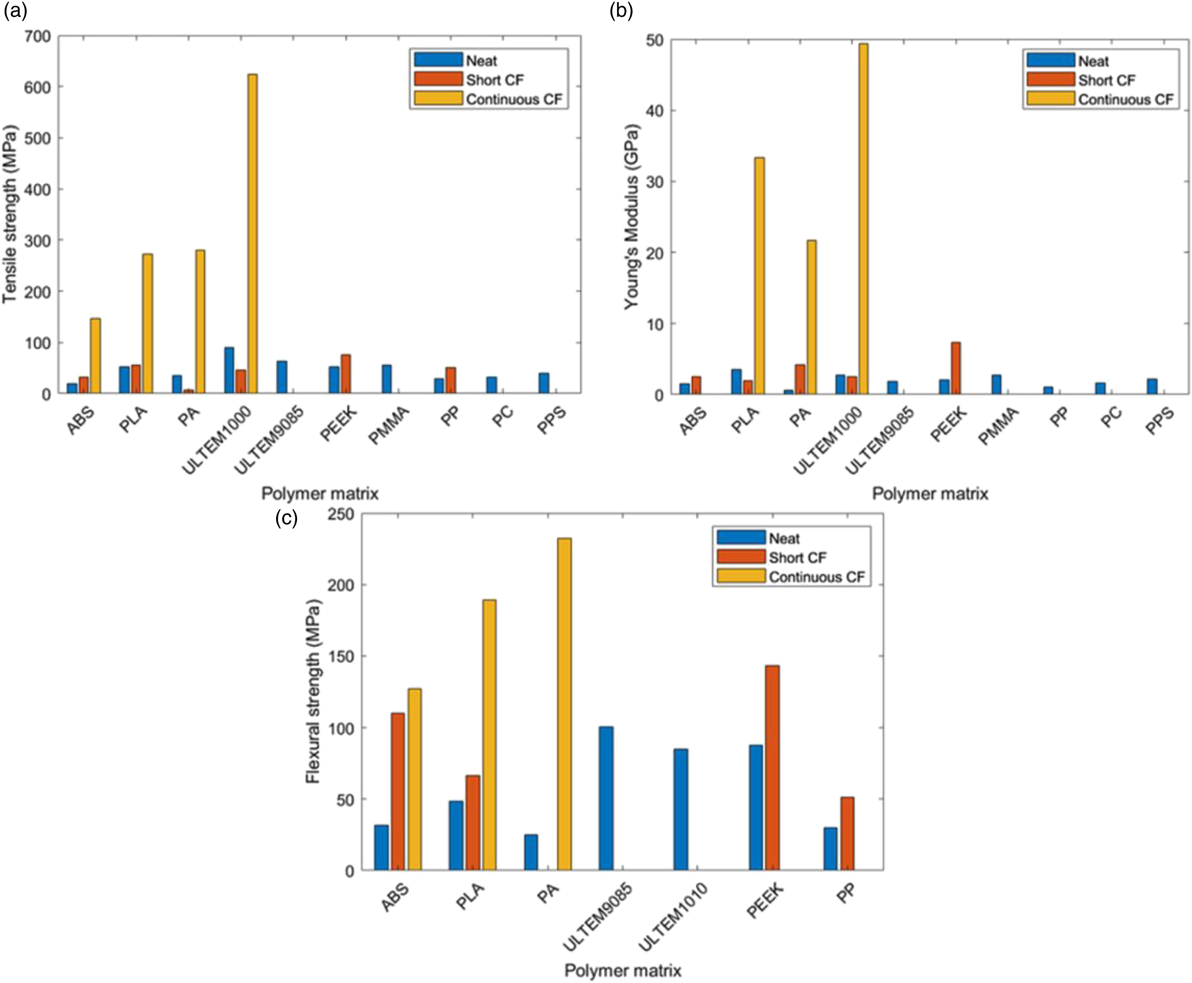
The reinforcing fibers (short or continuous) have excellent properties including high strength, lightweight, and anti-corrosion. The use of these reinforcing fibers in the common 3D printing process results in a fiber-reinforced composite with improved properties.7,8 The mechanical characteristics of continuous fiber reinforced composites (CFRC), such as Young’s modulus, tensile strength, and flexural strength, are significantly higher than those of short fiber reinforced or neat components (see Figure 2). Overall mechanical performance for fused filament fabrication-produced specimens. Average (a) tensile strength, (b) Young’s modulus, and (c) flexural strength values for neat, short, and continuous carbon fiber reinforced specimens.
9
List of review papers published relating to 3D printing of continuous fiber reinforced composites.

CFRC: Continuous Fiber Reinforced Composites; FDM: Fused Deposition Modeling.
Mechanisms of fiber-reinforced material’s 3D printers
Co-extrusion, dual extrusion, and compaction roller methods are three popular approaches for 3D printing CFRC.8,15,16 Figure 3 illustrates the schematics of these approaches. In the co-extrusion technique (Figure 3(a)), the thermoplastic filament and the reinforcing fiber are added separately to the head of the printing machine. In the dual extrusion method (Figure 3(b)), the thermoplastic filament and the fiber-reinforced are extruded separately through two nozzles on the build platform.
8
Finally, in the compaction roller technique (Figure 3(c)), a cartridge heater was secured to the nozzle body and used as a fixed shaft to support the compaction roller. The compaction roller has internal bearings to allow it to rotate freely around the cartridge heater.
16

An overview of continuous fiber reinforced composites 3D printing research
A summary of continuous fiber reinforced composites 3D printing research studies.


Most commonly studied mechanical tests and their trend during 2016–2021.

Number of researches done on pre-process, process, and post-processing of continuous fiber reinforced composites.

Published articles about continuous fiber reinforced composites 3D printing by country.
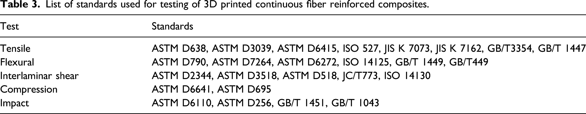
List of standards used for testing of 3D printed continuous fiber reinforced composites.
In comparison to CFRCs manufactured conventionally, printed CFRCs have inferior mechanical characteristics. The existence of flaws such as vacancies and poorer layer bonding are two primary reasons for this. As a result, several studies have attempted to enhance the mechanical characteristics of CFRCs by various pre-processing, processing, and post-processing methods (see Figure 5). As shown in Figure 5, the majority of the study focuses on the processing conditions, with just a few studies focusing on improving the mechanical characteristics of CFRCs through post-processing. As a result, it might be an intriguing topic for future research. Finally, Figure 6 shows a list of the nations where the studies were done. China, the United States, Japan, Iran, Spain, Ireland, Canada, and Singapore are the nations that have concentrated on CFRC 3D printing, according to this graph.
Pre-processing conditions
Impregnation
As indicated in Figure 5, pre-processing was the subject of 15 of the papers evaluated (mostly on impregnation). The application of impregnation is shown schematically in Figure 7. The findings revealed that impregnation quality has a significant impact on mechanical characteristics.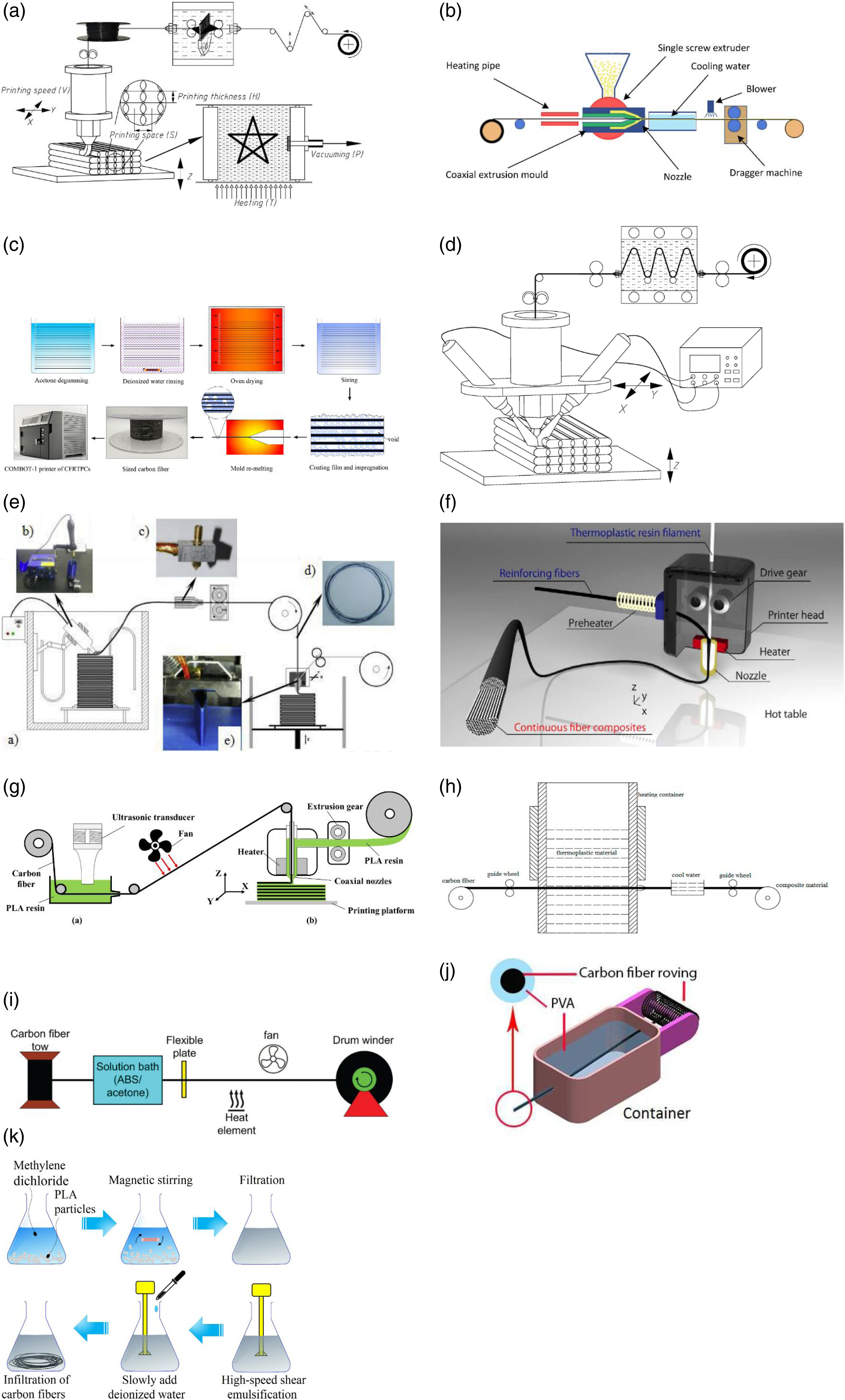
Ming et al. 18 produced the 3D printing filament by impregnating carbon fiber (CF)s with the thermosetting matrix at 130°C. The method employed multiple yarn rollers and spreading needles to stretch the fibers for a higher impregnation outcome (see Figure 7(a)). To make the continuous CF prepreg filament, Hu et al. 19 used a single screw extruder and coaxial extrusion molds. The continuous CF was heated in the heating pipe before entering the coaxial extrusion mold to keep it dry and warm and guarantee that the filaments are readily saturated with the molten resin. After impregnation, the continuous CF prepreg filament was placed in cooling water to solidify, and a fan was employed to maintain the filament dry in the next phase (see Figure 7(b)).
According to Liu et al, 20 the virgin CF was first extracted with acetone for 48 h, then repeatedly rinsed with deionized water and dried in an oven at 100°C for 2 h to remove the original epoxy sizing layer. The CF was then immersed in the aqueous PA845H solution for 12 h to guarantee that the polyamide solids penetrated the fiber bundle completely. Following that, the CF was aired at room temperature. The distribution of polyamide solids was uneven, with some gaps in the fiber bundle and a rough visible surface. As a result, a remolding nozzle with a diameter of 0.4 mm was suggested as a melt impregnation procedure. Finally, the sized CF and PA6 filament were utilized as raw materials to print composite components (see Figure 7(c)). This procedure enhanced the interlaminar shear strength of the PA6/sized CF sample by 42.2%.
Ming et al. 41 used a thermosetting matrix with a low viscosity of 1.3 Pascal-second at 130°C to impregnate continuous glass fibers (GFs). In the molten resin tank, many yarn rollers were used to stretch the fiber bundles and guarantee a broad resin impregnation area. The stretched fiber bundles were then molded into a cylinder form using a squeezing nozzle, the excess resin scraped off, and the impregnated continuous GFs extruded through a squeezing nozzle (see Figure 7(d)). Tian et al. 43 presented a recycling and remanufacturing method for 3D printed CFRC. From 3D printed composite components, continuous CF and PLA matrix were recycled in the form of PLA impregnated CF filament. The impregnated CF filament with a somewhat rough surface was produced by resolidified thermoplastic material adhering to the fiber (see Figure 7(e)). Due to enhanced surface characteristics, impregnated recycled continuous CF had a greater tensile strength (142 N) than the original printed filament (118 N).
Matsuzaki et al. 52 heated the reinforcing fibers before introducing them into the nozzle to improve the permeation of the fiber bundles with PLA; the heat diffuses to PLA, lowering its viscosity. The reinforcing fibers are automatically fed to the head by the movement of the resin filament, thus no extra equipment is necessary for feeding them. The heater within the printer head melts the PLA filament, merging the reinforcing fibers and PLA in the heated area (see Figure 7(f)).
Qiao et al. 55 impregnated CF by immersing it in a PLA/dichloromethane solution and treating it with ultrasonic waves at the same time. The impregnated CF bundle is then passed through a hole to scrape off any extra resin on its surface, and the dichloromethane solvent is volatilized under hot air. The results showed that the ultrasonic treatment had beneficial effects on the mechanical properties of the CFRC; when the amplitude increased, the tensile strength and elastic modulus rose first, then fall. Furthermore, the tensile strength and the tensile and flexural modulus of the material rose as the percentage of resin solution concentration increased (see Figure 7(g)).
Luo et al. 57 heated PLA particles to a molten state at 210°C in a sealed container. Then dry CF tow was run through the melt. Then, the impregnated CF was chilled in room temperature water (25°C) to produce a CF/PLA filament (see Figure 7(h)). A similar procedure was used by Mosleh et al. 61 to create CF/ABS prepregs. In a closed vessel at room temperature, 8 g ABS was swirled in 100 mL acetone for 30 min. To remove the surplus solution from prepregs, a flexible plate with a certain hole size was employed (Figure 7(i)). The findings demonstrate that impregnation before printing enhances mechanical characteristics and simplifies 3D printing. Likewise, Heidari-Rarani et al. 70 dissolved polyvinyl alcohol (PVA) in water and impregnated CF roving in this solution for 1 h at 60°C. The impregnated roving is passed through a die with a 1 mm hole and dried at room temperature to remove the excess PVA and create an approximate circular cross-section (see Figure 7(j)).
PLA particles (8% mass fraction) were introduced to a methylene dichloride solution by Li et al. 67 The DE-100LB high-speed dispersion and emulsification machine shears and emulsifies the PLA resin filtrate in methylene dichloride solution. The deionized water is then progressively added to process the aqueous PLA sizing agent to change the surface condition of the CFs (see Figure 7(k)). The tensile and flexural strengths of modified CFRCs were 13.8% and 164% greater than the original CF reinforced samples, according to the data.
Process (printing) conditions
The bulk of CFRC 3D printing research has focused on printing (processing) parameters rather than pre- and post-processing conditions (see Figure 5). The process factors can have a significant influence on mechanical properties, according to the literature. Table 2 outlines the parameters studied in the literature, with a focus on their effect on the tensile, flexural, and shear testing. Figure 8 depicts the investigated process variables. In this section, each of these variables will be discussed in more detail. Processing (printing) parameters assessed in the literature.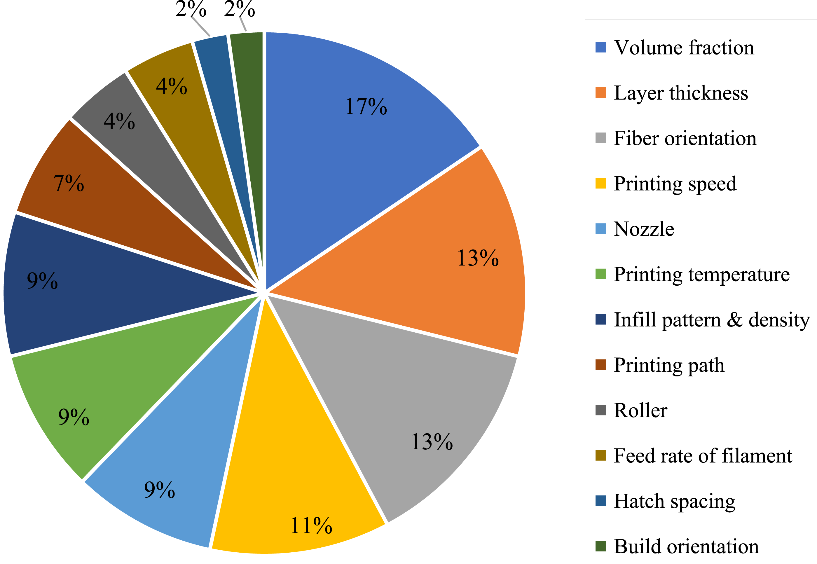
Fiber volume fraction
The FVF of CFRCs, as well as their tensile and flexural strength, are listed in Table 2. To further understand the relationship between the FVF and the mechanical properties of CFRCs, the data in Table 2 is presented in a graphical form (see Figure 9). As demonstrated in Figure 9, raising the FVF improves the mechanical characteristics. FVF is a very effective factor that may boost tensile and flexural strength up to 1000 MPa. Furthermore, the minimum FVF necessary to achieve a tensile strength greater than 600 MPa is 25%. Relation between fiber volume fraction and tensile (a) and flexural strength (b) of continuous fiber reinforced composites.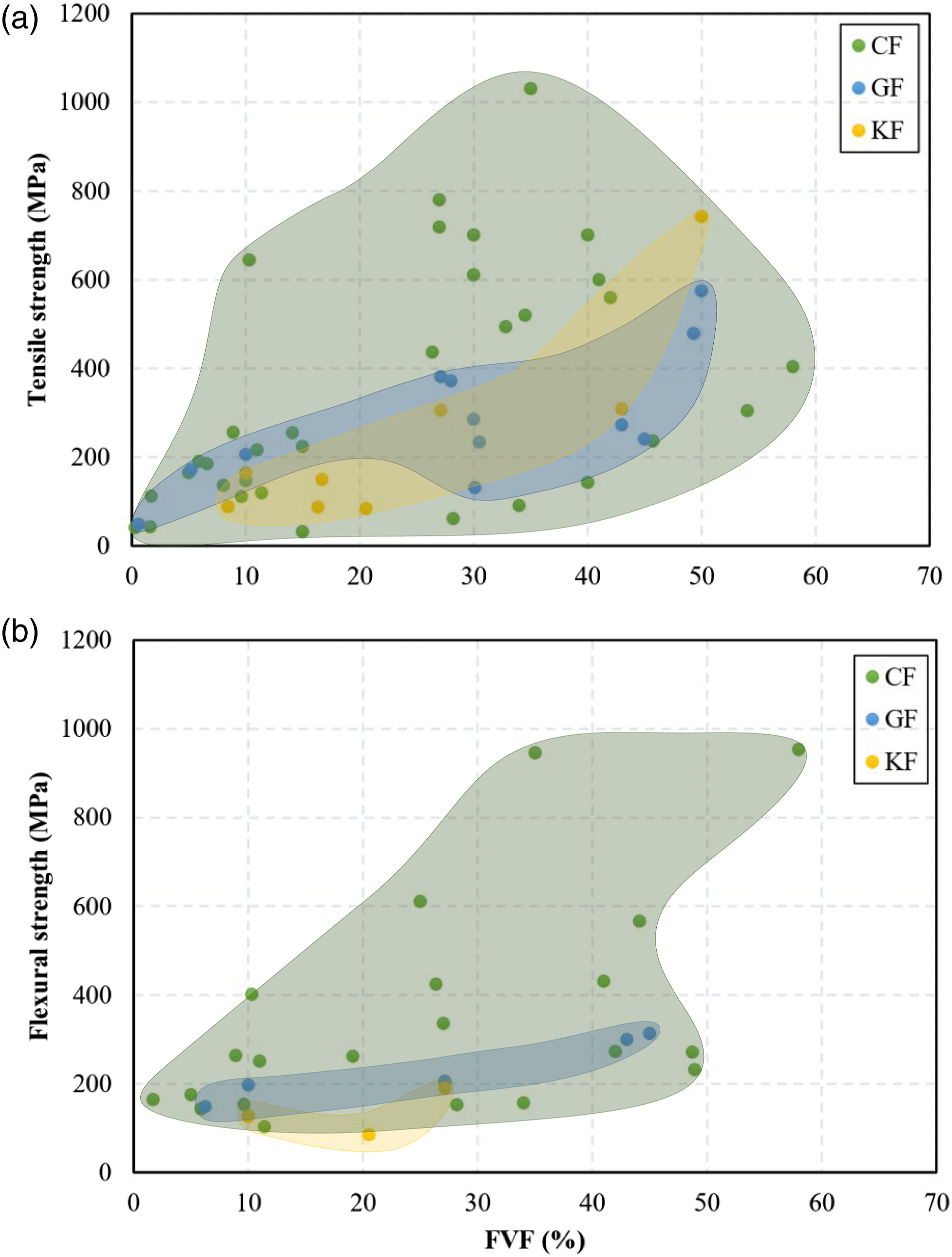
Printing parameters
Layer thickness, printing speed and temperature, hatch spacing, and filament feedrate (see Figure 10) are five critical printing parameters that highly influence the mechanical properties.
37
Schematic of process parameters for 3D printing of continuous fiber reinforced composites.
37

Layer thickness
The number of layers required to print the item is directly connected to the layer thickness, which in turn directly affects the printing time. Layer thickness influences manufacturing accuracy, interfacial bonding, performance, and mechanical characteristics of the samples. The mechanical characteristics of a sample with a smaller layer thickness are superior. However, decreasing the layer’s thickness lengthens the printing time. As a result, an optimal thickness value must be determined that gives acceptable mechanical characteristics and a reasonable printing time.
Printing speed
The printing speed can impact the filament retention time in the extruder head as well as the resin melting rate, and if the printing speed is low, the bond between the filament and the continuous reinforcing fiber will be better. As printing speed rises, the time that filament stays in the nozzle decreases, reducing pressure and impregnation time. In most studies, increasing printing speed resulted in a loss in mechanical characteristics (e.g., see Chen et al. 47 ), whereas in others, the influence of print speed on mechanical properties was shown to be insignificant.
Printing temperature
Temperature is a significant factor in CFRC 3D printing because it influences the impregnation quality of reinforcing fibers. When the printing temperature rises, so do the mechanical characteristics because the molten filament forms a stronger connection with the produced composite. However, printed composites lose their aesthetic characteristics and dimensional precision at extremely high temperatures. As a result, a temperature should be chosen that preserves the part’s appearance and dimensional accuracy while still providing acceptable mechanical characteristics. In some situations, the temperature did not influence mechanical characteristics, 19 which might be due to the printing temperature’s restricted range.
Printing of PLA/CF at 180°C–240°C showed that the flexural strength and modulus increased as the temperature rose. On the other hand, the sample produced at 240°C lost its surface precision due to PLA melt overflow. As a result, the maximum suggested printing temperature was 230°C. 37 Chen et al. 47 found similar results in 3D printing PLA/GF samples at temperatures ranging from 190°C to 230°C. According to the findings, boosting the temperature enhanced the mechanical characteristics. However, when the printing temperature surpasses 210°C, it becomes difficult to maintain the sample’s dimensional stability, particularly at the edges. As a result, 210°C has been chosen as the optimal printing temperature. Refer to Wang et al. 91 (CF/Pb50Sn50 composites) and Wang et al. 53 (PLA/GF composite) for additional comparable cases.
Hatch spacing
This parameter had not been thoroughly examined. Nevertheless, Tian et al. 37 found that utilizing a smaller hatch spacing resulted in improved mechanical characteristics. They used hatch spacing ranging from 0.4 to 1.8 mm. The average flexural strength increased from 130 to 335 MPa and the flexural modulus improved from 6.26 to 30 GB when hatch spacing was reduced from 1.8 to 0.4 mm.
Filament feedrate
The filament feedrate specifies the volume of material fed into the printing head per unit time. It controls the inner pressure of the printing head and the extrusion speed of the melt material. 37 Tian et al. 37 printed PLA/CF composites at feedrates ranging from 60 to 160 mm/min. The hatch spacing, layer thickness, printing temperature, and printing speed were set to 1.2 mm, 0.5 mm, 100 mm/min, and 210°C, respectively. Increased feedrates resulted in a drop in fiber content while increasing the internal pressure of the liquefier and the contact pressure between the nozzle and the deposited layer. Due to the contradicting effects of these observations on the composite’s mechanical properties, the relationship between filament feedrate and mechanical properties is unclear. A feedrate of 80–100 mm/min was proposed to balance these opposing effects. 37 Liu et al. 20 observed similar findings in the 3D printing of PA6/CF composites. According to Liu et al, 20 using a small feedrate (without adjusting other parameter values) leads to deposition of an insufficient amount of material, which results in low forming pressure and poor interfacial performance.
In summary, mechanical properties improve as the feedrate of the filament increases to some extent. The mechanical properties remain constant as the feedrate of the filament increases further. More study, however, is required to understand better the influence of feedrate on the mechanical characteristics of CFRCs.
Fiber orientation
As shown in Figure 11, the fibers can be printed in two ways: concentric and isotropic. In the isotropic form, they can be printed at varied angles (0, ±45, 90°). Fiber reinforcement configuration, (A) concentric, and (B) isotropic – 0°, and (C) fiber orientations in a single layer.
45

In printing PA/CF composites, Pyl et al. 24 adjusted the fiber orientations of the composites to 0 unidirectional, 0/90, 0/90/±45, and ±45°. According to the findings, composites with the fiber orientations of 0 unidirectional, 0/90, 0/90/±45, and ±45° had the highest tensile strength in that order. The strain to failure of the composites printed at 0 unidirectional, 0/90/±45° was nearly identical, but the strain to failure of the ±45° sample was about four times that of the others.
Mohammadizadeh et al. 36 printed nylon matrix composites reinforced with carbon, glass, and Kevlar fibers. The sample fiber orientations were concentric and isotropic. The isotropic composites showed greater mechanical qualities than those printed in a concentric configuration. Concentric and isotropic infill arrangements were also employed by Yu et al. 42 Onyx/CF composites with a concentric infill pattern offered higher flexural strength and energy absorption than composites with an isotropic infill pattern. Comparable findings were obtained by Araya-Calvo et al., 45 who employed concentric and isotropic infill patterns to print PA6/CF composites. Compressive and flexural tests were performed and it was found that the composites with a concentric pattern perform better. Dickson et al. 49 used carbon, glass, and Kevlar fibers to reinforce nylon matrix composites. The composites with isotropic patterns had higher tensile and flexural strength and modulus than concentric specimens. In addition, the flexural testing revealed that the concentric pattern composites perform better in bending than in tension.
González-Estrada et al. 65 used angles of 0, 45, and 90° to print nylon/GF composites. The composites printed at 0, 45, and 90° had the highest strength and modulus, respectively. Nylon/KF composites with angles of 30, 45, and 60° were created by Shi et al. 68 The highest yield stress was for 30, 45, and 60°, respectively.
In conclusion, increasing the print orientation (from 0 to 90°) reduces the mechanical characteristics of composites produced with the isotropic pattern. The effect of fiber orientation in CFRCs is well understood mathematically (classical lamination theory 92 ), and evidence suggests that 3D-printed composites behave exactly. 93 There are conflicting findings on whether the isotropic and concentric patterns provide superior mechanical characteristics. In some circumstances,36,49 an isotropic pattern gave higher mechanical qualities, whereas, in other studies,42,45 concentric patterns were found to produce better mechanical properties.
Build orientation
Three potential orientations for 3D printing composites are flat, on-edge, and upright. This parameter has only been investigated by a few scholars, and further research is needed. Chacón et al. 35 printed nylon matrix composites reinforced with carbon, Kevlar, and glass fibers in flat and on-edge orientations. The on-edge composites had higher impact strength, according to the results of Charpy tests performed on them.
Infill pattern and density
Naranjo-Lozada et al. 39 created Onyx/CF composites with infill densities of 10% and 70% with triangular and rectangular infill patterns. Composites with a triangle design performed better in tensile tests than those with a rectangular pattern. The modulus of elasticity improved when the infill density of the specimens was increased from 10% to 70%, but the tensile strength of these two composites was nearly identical. González-Estrada et al. 65 printed nylon/GF and nylon/CF composites with triangular, rectangular, and hexagonal infill patterns. The samples' infill density was 20% and 50%, respectively. Higher stiffness and ultimate tensile strength were achieved with the triangular pattern. Changing the infill density from 20% to 50%, on the other hand, has no noticeable impact on the properties indicated. Mei et al. 64 printed nylon matrix composites reinforced with carbon, glass, and Kevlar fibers. The composite’s infill patterns were rectangular, hexagonal, and triangular. The samples had the same number of concentric fiber rings and fiber layers. It was discovered that as the number of concentric fiber rings and fiber layers rose, so did the tensile strength and modulus.
According to the articles listed above, increasing the infill density improves mechanical qualities slightly. In addition, the triangular, hexagonal, and rectangular infill patterns, respectively, offer the best mechanical qualities. The explanation for the rectangular sample’s superiority in Mei et al. 64 is that these samples had more rims than the other samples.
Compaction during 3D printing
It was observed that applying pressure during the printing process substantially enhances the mechanical characteristics of CFRCs.16,28 The mechanical characteristics of composites compacted during printing were even superior to those of hot-pressed composites.
16
This is mostly due to the elimination of vacancies and better layer bonding. Ueda et al.
16
created two samples, one with compaction roller technique (see Figure 3(d)) and the other with the hot-pressing method. The results demonstrated that the compaction-roller-made composite has a better fracture surface, superior mechanical properties, and lower void fraction than the hot-pressed sample. Zhang et al.
28
printed PLA/CF composites with a compaction roller (see Figure 12). The sample’s tensile and flexural strength rose with increasing pressure to 644.8 MPa and 401.24 MPa, respectively. However, as the pressure is increased, the quality of the sample surface degrades, and the sample may fail. Schematic of the 3D-printing machine with pressure roller.
28

Along with the process parameters described previously, novel approaches have been presented to improve the mechanical properties of CFRCs. Shang et al, 15 for example, demonstrated that using a sinusoidal-path extrusion 3D printing method improved inter-line bonding and hence the mechanical properties of the 3D printed composites. However, this procedure necessitates using a robotic arm system, which is costly. On the other hand, this technique enables the creation of complex shapes and larger build volumes.
Post-processing
Hot pressing and vacuuming are two feasible options for post-processing and thereby increasing the mechanical properties of CFRCs. Performing post-processing on CFRCs resulted in extremely high tensile and flexural strength increases, according to the literature review. Despite this, the number of papers devoted to CFRC post-processing is rather small (see Figure 5). One reason for this might be the high costs of post-processing operations. As indicated in the previous section, Ueda et al.
16
used a compaction roller to make composites (see Figure 3(d)). They also hot-pressed 3D-printed composites for 10 min at a temperature of 230°C and a pressure of 0.1 MPa (see Figure 13). After hot-pressing, the sample’s thickness and weight were reduced by 16% and 1.5%, respectively. The hot-pressed sample had somewhat poorer flexural characteristics than the compaction roller-produced sample. As a result, the compaction roller technique may be a better option than hot pressing. Hot-pressing operation on continuous fiber reinforced composites.
16

Ming et al. 18 used a vacuum chamber to cure 3D printed CFRCs at various curing pressures and temperatures (see Figure 7(a)). The specimens were first exposed to vacuum pressures of −10, −30, −50, −70, and −90 kPa. The results revealed that the more negative the pressure, the better the specimens' strength and flexural modulus. The fibers were discovered to be covered with a thin layer of resin before curing, and there were several voids inside the specimens. But after curing, the fibers were evenly covered with resin, and the interior voids were significantly reduced. Negative pressure can increase resin diffusion and fiber impregnation, according to these findings. A small pressure increase led to a significant decrease in fiber content, thus, it is a vital parameter that must be regulated. Curing temperatures of 150–190°C were also applied to the samples. The results revealed that increasing the curing temperature from 150 to 170°C enhanced flexural strength and modulus to their maximum levels. On the other hand, the flexural strength and modulus decreased dramatically as the curing temperature increased from 170 to 190°C.
Conclusions and summary
The majority of CFRC research employing FDM technology has been covered in this review paper. The parameters impacting the mechanical properties of CFRCs were evaluated. The following are the conclusions reached: • Impregnation is critical in pre-processing, and the results reveal that the higher the impregnation quality, the better the mechanical qualities. Pre-heating the fiber, applying ultrasonic vibration, and pre-impregnation inside a solution all help to increase impregnation and, as a result, improve the mechanical characteristics. • The following findings are drawn from examining the printing parameters: o In general, improving the mechanical properties of CFRCs was obtained by increasing the FVF and infill density while lowering the layer thickness, printing speed, and hatch spacing. o The mechanical properties of the samples improve as the printing temperature rises. But at much higher print temperatures, the appearance and dimensional precision of CFRCs deteriorate. o As the filament feedrate is raised, the mechanical characteristics improve initially and then remain constant. o In the specimens printed with an anisotropic pattern, the larger the angle of the fibers, the lower the mechanical properties (0-degree fiber angle provides the best mechanical properties). o The triangular, hexagonal, and rectangular infill patterns resulted in the best mechanical properties, respectively. o The use of hot compaction rollers enhanced mechanical properties significantly; however, the samples should not be over-pressurized. • Proven post-processing methods for improving the mechanical properties of CFRCs include hot pressing, vacuuming, and post-heat treatment.
However, a lot of topics in CFRC 3D printing are either unexplored or underexplored, which could be relevant research subjects in the future: 1. More research into CFRC dynamic, fatigue, creep, impact, indentation, wear, and friction testing is needed. 2. The impregnation and post-processing activities should be given special attention. In addition, more research is needed to understand the impact of post-processing factors on composites' mechanical properties. 3. The influence of printing factors such as build orientation, hatch spacing, and printing patterns (isotropic and concentric) on the mechanical characteristics of CFRCs should be investigated further. 4. Kevlar and glass fiber reinforced composites' mechanical characteristics should be examined further. The impact of FVF on the bending strength of these composites should be studied in particular. 5. The ability to undertake post-printing procedures such as forming and machining, as well as the consequences of these operations on the features and characteristics of 3D printed CFRCs, is further intriguing topics for wider use of these composites.
Footnotes
Declaration of conflicting interests
The author(s) declared no potential conflicts of interest with respect to the research, authorship, and/or publication of this article.
Funding
The author(s) received no financial support for the research, authorship, and/or publication of this article.