
Abstract
The use of additive manufacturing has been widely developed in the industry due to its ability to make complex shapes. The use of reinforcing fibers has provided a wider design capability in this field. Due to the effect of the number of fibers reinforced used on the mechanical properties, the study of the obtained mechanical properties is of great importance. This paper presents the experimental findings of tensile loading and three points bending fatigue tests performed on polymer-based composites (Onyx (which is CF-PA6) and reinforced Onyx with continuous glass fiber (CF-PA6 + GF) using Fused Filament Fabrication. Tensile properties of various types of printing conditions (Solid, Triangular, Rectangular, and Hexagonal fill patterns) have been compared. The coupled frequency amplitude affects the nature of the overall fatigue response which can be controlled by the damage mechanisms accumulation and/or by the self-heating. For fatigue loading, self-heating has been observed and yielded a temperature rise to about 60°C which is more than the glass transition temperature of the polymer. Multi-scale damage analysis of the sample in fatigue showed that the first observed damage phenomenon corresponds to the debonding of the filaments which leads to the propagation of transverse cracks.
Introduction
Additive manufacturing (AM), or rapid prototyping (RP), or solid-freeform (SFF), also known as the 3D printing process1–5 is a new generation of the manufacturing method of the parts. Different additive manufacturing methods are oriented to fabricate the different functional parts in the last 20 years. In fact, AM methods have been used in different industries such as the aerospace industry,6,7 medical applications,4,8–12 automobile industries,6,7 construction,13–16 and so forth. Additive manufacturing (AM) is a novel technology that enables the rapid fabrication of physical models directly from 3D computer-aided design (CAD) data with no conventional tooling or programming requirement.
The most popular SFF technologies to date are Stereo-lithography (SL), Laminated object manufacturing (LOM), Fused Filament Fabrication (FFF), Selective laser sintering (SLS), and Multi-jet modeling (MJM).17,18 Among all the stated AM fabricating methods above, fused filament fabrication (FFF) (which is known as Fused Deposition Modeling (FDM)) and Selective Laser Sintering (SLS) have been the most used rapid prototyping (RP) methods for the fabrication of polymer composite parts. As for the comparison between FFF and SLA methods, FFF parts have lower mechanical properties. 19 But FFF has some advantages such as less expensive materials and machines, which result in a cost-effective process, 20 and minimum waste of the used materials.
Generally, fused filament fabrication (FDM) is one of the most common and widely used AM technologies. As for a brief introduction, the raw material, which is in rolled filament form (feedstock), is fed into a machine via a pinch roller mechanism. The feedstock is melted in a heated liquefier section. Also, the un-melted part of the feedstock, which is the solid portion of the filament acting as a piston to push the melt through a print nozzle, then is deposited on the platform (bed). The extruded material (polymer (s) or polymer composite) solidifies and adheres, to the previous printed and solidified layers rapidly, to fabricate the complex desired parts. 21
Mostly, the used feedstocks for FFF are thermoplastic with low levels of crystallinity or amorphous according to have as little shrinkage as possible in the final fabricated parts. Using the FFF process for the manufacturing of composite parts is increased in recent years. It is observed that the use of reinforcement has improved the benefits of shrinkage and strength, both. 22 Also, one of the stated aims of the reinforcements usage in FFF is to overcome the non-printability of some raw materials, related to their high coefficient of linear thermal expansion.22,23
Lectcher and Waytashek, 24 have studied the fatigue behavior of the 3D-printed PLA specimens. They used “Makerbot Replicator 2x” 3D-printer and studied the effect of the raster angle by choosing the, 0°, 45°, and 90° raster angles. Their fatigue tests were applied in the range of 2–20 Hz as frequencies under the fully reversed sinusoidal axial force. According to their result, it was found out that manufacturing direction has effects on the fused deposition modeling processed PLA samples. Similarly, Afrose et al. 25 have studied the fatigue behavior of the 3D-printed PLA specimens by the “Cube-2” 3D printer. They had experimental studied on the effect of the build orientation on the fatigue behavior of fused deposition modeling processed PLA dog-bone flat specimens. The fatigue test was applied under the 1 Hz, as frequency. Their results showed that related ultimate tensile stress of printed samples in X-direction (0°) was the highest which was 38.7 MPa. The related ultimate tensile strength values of the printed samples in Y-direction (90°) and 45°-direction were 31.1 and 33.6 MPa, respectively. But 45°-direction printed samples had the highest fatigue life in comparison with printed ones on the X- and Y-directions. Ezeh and Susmel 26 reported the fatigue behaviors of the 3D-printed PLA samples by considering mean stress effects, and also a unifying design curve was proposed. Ziemian et al. 27 applied tensile-fatigue tests on the manufactured ABS samples by FDM. According to the results, the printed samples with raster orientation at +45/−45° had higher fatigue life and a higher storage modulus, than the 0°, 45°, and 90° printed ones. Imeri et al. 28 studied on fatigue behavior of fiber-reinforced additive manufacturing specimens, printed by “Markforged Mark Two 3D printer.” They analyzed the data collected with analysis of variance (ANOVA) according to investigate the importance of some printing parameters. According to the results, a correlation between the type of reinforcements and the printing pattern of reinforcements was found out. As for the effect of the used reinforcement, carbon fiber showed better fatigue life. Also, as the effect of the printing pattern of reinforcements, the fatigue life performance was improved by the use of more rings of reinforcement. But, in the case of concentric infill, the fatigue performance decreased by an increase in the number of rings. Alberto D. Pertuz et al. 29 studied the effect of filling percentage, filling pattern of the nylon matrix, fiber materials (glass fiber, Kevlar, and carbon fibers), fiber orientation, and the number of concentric rings used in the printing configuration, in the printed samples by MarkForged Mark Two printer. The printed nylon matrix samples in triangular filling pattern and matrix density of 20%, by use of the carbon fiber reinforcement at 0-degrees, had better fatigue performance. Lee et al. 30 studied the printed ABS and ABS-plus samples by FDM. They have studied the effect of the printing orientations on the fatigue performance of 3D-printed samples.
One may therefore conclude that the mechanical properties of 3d-printed pieces are limited. In this work, the mechanical properties have been improved by reinforcing with the fibers such as s, carbon fibers, etc. The used material as raw material was Onyx, which was CF-PA6. Onyx is introduced as one of the newest matrix materials for fabricating composite parts with Markforged 3D printers. The Onyx (or CF-PA6), which has been introduced as a matrix for fabricating the polymer composite parts, is composite by itself. First, after some physical-chemical characterizations, various types of printing conditions (solid, triangular, rectangular, and hexagonal fill patterns) have been performed and the comparison between them in term of tensile properties have been done. Then, the continuous glass fiber was used for manufacturing the reinforced CF-PA6 with continuous glass fiber (FDM of composite) and some analyses were presented.
The structure of this article is as follows: the section of material description and methods is dedicated to a description of the main physico-chemical characteristics and the modeling of the viscoelastic behavior of Onyx using the DMA test. The developed experimental procedure for fatigue testing at several amplitudes has been performed. In the experimental results and discussion section, the obtained experimental results from applying the quasi-static and fatigue loadings and multi-scale damage analysis are presented and discussed.
Material description, 3D printer device, and characterization methods
Raw material
Carbon fiber-reinforced PA6 composites (CF-PA6)
The used raw material was a filament of reinforced PA6 by about 6.5Wt% chopped carbon fiber (CF-PA6), with the commercial name of Onyx. Onyx (CF-PA6), which has also been introduced as a matrix for fabricating the polymer composite parts, also is composite by itself, too. It is a sort of combination and fusion of engineering plastic as its matrix and chopped carbon fibers as its reinforcements with the mass content of 6.51% in 93.49% of the matrix. It is a specially tuned PA6 copolymer (polyamide) filament with a chopped carbon fiber blend, adding great strength and stiffness unique to FFF printing. The infill patterns of the manufactured short carbon fiber-reinforced composites specimens were triangular, rectangular, hexagonal, and solid infill. Already, Ahmadifar et al., 31 have studied the effect of some main process parameters on the thermal and mechanical behavior of Onyx.
Reinforced (CF-PA6) with continuous glass fiber
By Mark Two it is possible to print the continuous reinforcements in concentric or/and isotropic patterns. By choosing the Isotropic infill pattern, the designer will be capable to consider the specific printing direction(s) for the continuous reinforcement. The isotropic infill pattern was chosen as the continuous reinforcement printing pattern. The printing directions of the reinforcement layers –0° and 45° (Figure 1) were considered to decrease the anisotropic behavior of additive manufactured specimens. The glass fiber was used as the continuous reinforcement material. The specimens were manufactured in forty layers (the number of the matrix and reinforcement layers, both). Four layers were considered as the number of reinforcement layers. The glass fibers were deposited as sixth, seventh, thirty-fourth, and thirty-fifth layers. Orientation of the deposited glass fiber.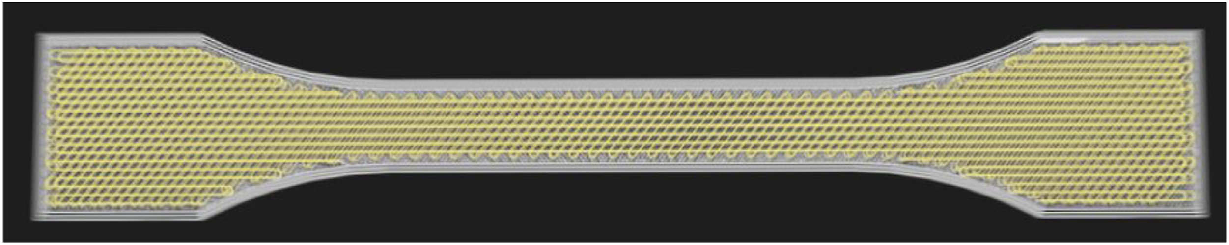
3D printer device
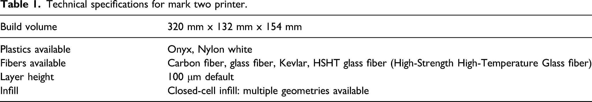
One of Markforged’s desktop printers is Mark Two Printer. In this research, the used 3D Printer device was Mark two printer (Figure 2). This printer manufactures the parts from Nylon (PA6) or Onyx (CF-PA6) materials which have been developed by Markforged. By the way, it is possible to use continuous reinforcement fibers of carbon or, glass, or Kevlar. Some stated technical specifications for Mark Two printer are listed in Table 1.
21
This printer has two extruders, one of them is allocated to deposit the matrix material and another one is allocated to the reinforcement materials. So, the temperature of each nozzle will not be the same. Mark Two printer (a) and printer during the print of the required specimens (b). Technical specifications for mark two printer.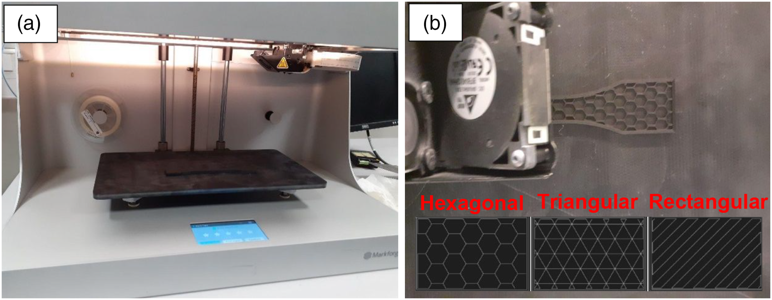
As was stated, Mark Two can fabricate the different structures at different percentages. According to the related printer software, it is possible to choose three dominant types of structure, which are rectangular, triangular, and hexagonal. Also, during our study, we sort of consider the solid fill printing condition, as another structure or infill pattern, as its different structure from the other ones. In fact, in the solid fill pattern, the raster orientations of the layers were +45 °, −-45 °, +45 °, −-45 °, …. The used temperature for the printing process of CF-PA6 (Matrix material) and Glass fiber (reinforcement material), were about 276°C and 253°C, respectively.
Methods of characterization and experimental procedure
Microscopic observation
The ZEISS optical microscope was used to observe the used CF-PA6 filament and orientation of chopped carbon in the filament. Microscopic observations and image analysis, using scanning electronic microscope (HITACHI 4800 SEM), have been done to qualitatively examine the composite microstructure, especially damage analysis.
Differential scanning calorimetric (DSC)
DSC measures specific heat capacity by heating a sample and measuring the temperature difference between the sample and a reference. This method is used for measuring the melting points, glass transition, crystallization temperature, and the heat capacity of the used CF-PA6 filament. the measurement was carried out using the DSC Q10.
DMTA measurement
Thermo-mechanical analysis (DMTA) flexural tests have been attained to measure the major transitions temperatures on the printed sample made of CF-PA6, using the DMA Q800 instrument from TA Company. The flexural test has been realized at the following condition: temperature range varying from 30 to 80°C, temperature rate of 2°C/min, and the frequencies of 1, 2, 5, 10, and 30 Hz.
Quasi-static tensile test
The used sample was according to the standard ISO 527-1. Quasi-static tensile experiments have been achieved with the INSTRON 5966 machine, loading cell of 10 kN, and the displacement rate is 5 mm/min. In order to the reproducibility of the results, at least four samples were carried out in the Tensile Test study.
Fatigue test
Three points bending fatigue tests have been performed at different applied maximum strains (εmax). The minimum applied strain (εmin) was chosen to be equal to 10% of the maximum applied strain. The chosen strain-ratio was thus (Rσ = 0.1), and the mean strain-level was equal to 0.55 εmax.
During fatigue loading, the temperature rise, due to the composite self-healing, has been measured on the surface of the specimen using an infrared camera (Raynger- MX4). An Optris PI450 infrared camera was used (Figure 3). The sample under the three-point bending fatigue test (a) temperature measurement during the fatigue test by the infrared camera (b).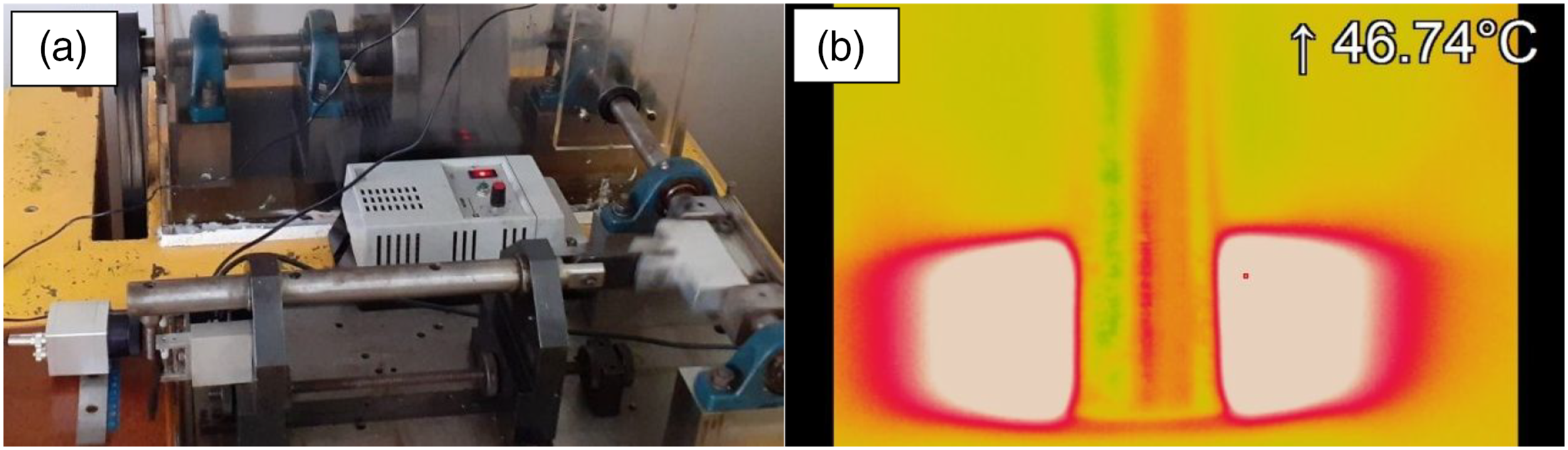
Multi-scale damage analysis in fatigue
The macroscopic damage evolutions have been estimated through the measurement of Young’s modulus evolutions. Microscopic damage observations were performed by subjecting CF-PA6 specimens to a fatigue loading under specific loading amplitude with a frequency of 10 Hz. The observation area corresponded to a polished thickness surface of the rectangular composite with a geometry of 120 × 10 × 4 mm3.
Experimental results and discussion
Microstructure analysis
According to the observation of the carbon fibers (Microscopy Observation) under the optical microscopy, the size range of the disturbed chopped carbon fibers was about 10 to 312 micrometers, according to Figure 4(a). Note that the diameter of the used CF-PA6 filament was 1.75 mm. According to the optical observation of the used filament (Figure 4(b)), the chopped carbons of the CF-PA6 filament, were directional. Microscopy observation of the chopped carbon fibers in the used filament (a), CF-PA6 filament (b), and CF-PA6 reinforced with continuous glass fiber (c).
Moreover, the microstructure of CF-PA6 reinforced with glass fiber can be observed in Figure 4(c). The continuous glass fiber is marked at the top of Figure 4(c).
Thermo-mechanical properties
Thermal analysis

Thermo-mechanical properties
Glass transition temperature
Main transition temperatures due to molecular mobility as a function of the temperature have been measured using the DMTA test. This test can be useful to analyze the induced self-heating phenomenon and to relate it to the measured temperature rise during a fatigue test at different amplitudes. Figure 5 shows the evolution of the storage and loss moduli versus temperature on the CF-PA6 sample. As it can be noticed, CF-PA6 presented a glass transition of nearly 60°C. DMTA test result: Evolution of the storage, loss moduli, and loss factor versus temperature.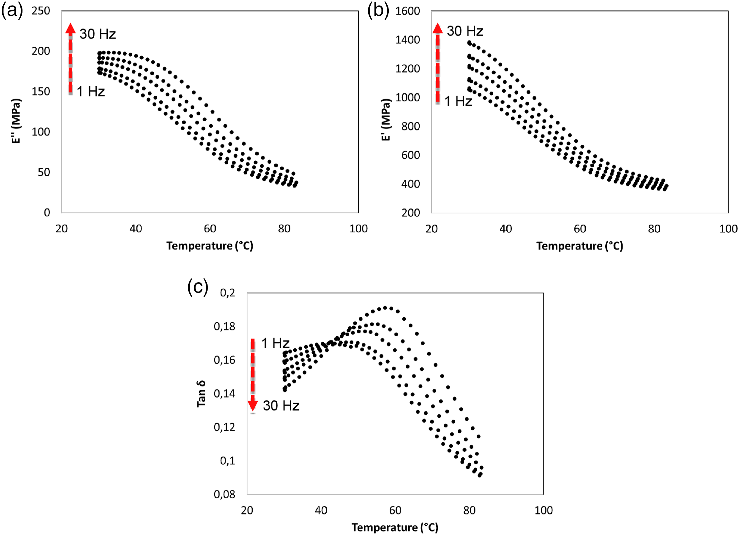
The elastic or viscous response of CF-PA6 can be measured as a function of temperature using DMTA; it is possible to understand the true internal damping of the system. One can suppose that CF-PA6 has rigid stability at ambient temperature while the storage modulus continuous to decrease slowly until 80°C due to the increase of macromolecular chain mobility.
Viscoelasticity modeling by Cole-Cole principle
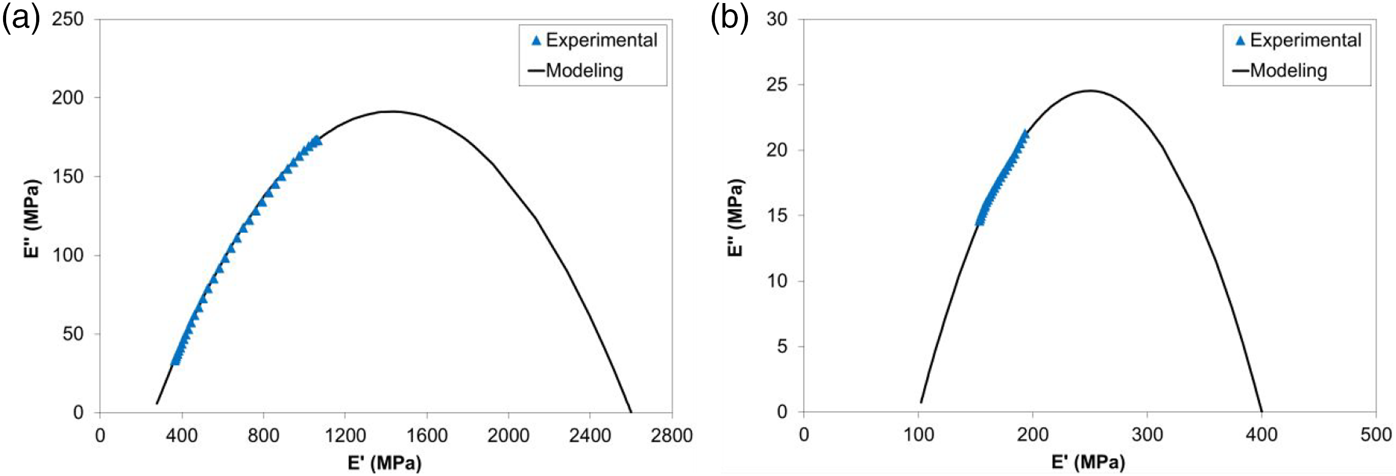
Various approaches have been used to study the viscoelastic properties in the temperature range between the glassy and rubbery domain, and different models have been proposed to predict these properties. These models generally represent the curve of E″ (loss modulus) as a function of E′ (storage modulus), and the curve is known as the Cole-Cole diagram. For the validation of the theoretical model, experimental data obtained by the dynamic mechanical, thermal analysis (DMTA) tests are required. After DMTA tests, an asymmetric Cole-Cole diagram has been plotted (Figure 6). The behavior of polymers can be analyzed by the bi-parabolic model according to the Perez model, the equation is as follow Cole-Cole plot of (a) CF-PA6 + GF and (b) CF-PA6.


Perez model parameters for CF-PA6 and CF-PA6 + GF.

Quasi-static tensile behavior
Effect of fill patterns
As it was stated, the three main infill patterns which were triangular, rectangular, and hexagonal were considered to print the tensile specimens, by Mark Two printer. So, the tensile samples were printed by use of the CF-PA6 filament under these stated main infill patterns. Their tensile strength was compared with each other and also with the solid infill pattern (whose infill percentage was 100%). So, the tensile strength was considered as the criterion to make the comparison. The Tensile test results of the different infill pattern samples, which were made of CF-PA6 are listed in Figure 7 and Table 4. Quasi-static tensile curves (a) and strength evolution (b). Tensile test results of the printed samples under the different infill patterns, made of CF-PA6.
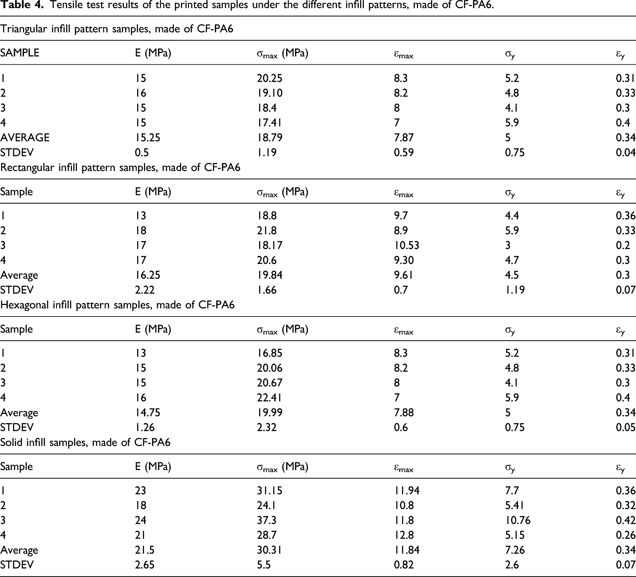
According to the tensile test results of the printed samples by the use of CF-PA6, the tensile strength of triangular, rectangular, hexagonal, and solid infill were 18.79 ± 1.19, 19.84 ± 1.66, 19.99 ± 2.32, and 30.31 ± 5.5 (MPa), respectively. So, as it is clear, the tensile strength of the triangular specimens is the lowest in comparison with the other infill patterns. Then the rectangular infill patterns are more than triangular, but less than hexagonal. The most tensile strength is related to the solid infill samples. As it was extracted from the results, by changing the infill pattern of the printed CF-PA6 samples from triangular to rectangular and hexagonal, the tensile strength has been improved 5.9% and 6.4%, respectively. But by changing the infill pattern of the printing process of the samples which were made of CF-PA6, from the triangular to solid infill, the tensile strength improved almost 61.3% (Figure 7).
Effect of the continuous reinforcement on different infill patterns
The Tensile samples were printed by use of the CF-PA6 filament and continuous glass fiber, under the main stated infill patterns. Again, their tensile strength was compared with each other and also with the solid infill pattern (whose infill percentage was 100%). So, the tensile strength was considered as the criterion to make the comparison. The tensile test results of the different infill pattern samples, which were made of CF-PA6 reinforced with continuous glass fiber, are in Figure 8. According to the tensile test results of the printed samples by use of CF-PA6 reinforced continuous glass fiber, the tensile strength of hexagonal, rectangular, triangular and solid infill were 60.04 (a) Quasi-static tensile curves and (b) Strength evolution.
Fatigue behavior analysis
Effect of using the continuous reinforcement
Figure 9 shows the Wöhler curves obtained in three points bending fatigue tests at a frequency of 10 Hz for CF-PA6 (Onyx) and CF-PA6 reinforced with continuous glass fiber (Onyx+GF) samples. Wöhler curves for CF-PA6 (Onyx) and CF-PA6 reinforced with continuous glass fiber (Onyx+GF) samples at 10 Hz.
The curves evidence the effect of the fiber reinforcement. One can note that in the case of the printed specimens with CF-PA6, for applied strain equal to 4.5%, the fatigue life is about 200,000 cycles whereas the fatigue life is about 2000 cycles for CF-PA6 reinforced with continuous glass fiber.
It can be established that for CF6-PA6 composite, the fatigue design can be efficiently optimized through glass fiber reinforcement. Regarding CF-PA6 reinforced with continuous glass fiber samples at 10 Hz, it can be noted that the Wöhler curve shows a linear form. However, for the CF-PA6 sample a bi-linear form can be observed.
Wöhler curves obtained from fatigue tests for CF-PA6 and CF-PA6 reinforced with continuous are shown in Figure 9. One can indicate that there is a small difference between the curves at high amplitude while at low strain amplitude, the Wöhler curve is shifted.
Relative Young’s modulus evolution and self-heating phenomenon
Figure 10 shows the evolution of the relative stress during fatigue tests for CF-PA6 and CF-PA6 reinforced with continuous glass fiber samples at the frequency of 10 Hz. All samples exhibit a fatigue behavior mostly governed by the Mechanical Fatigue (MF) nature due to damage phenomenon, whereas for high amplitude, the Induced Thermal Fatigue (ITF) is the predominant nature of the fatigue behavior at low cycles for CF-PA6 and CF-PA6 reinforced with continuous glass fiber samples. The detailed analysis of MF and ITF has been presented in previous work.
32
Evolutions of the relative stress (∼Young’s modulus) during fatigue tests for (a) CF-PA6 (Onyx) and (b) CF-PA6 reinforced with continuous glass fiber (Onyx+GF) samples.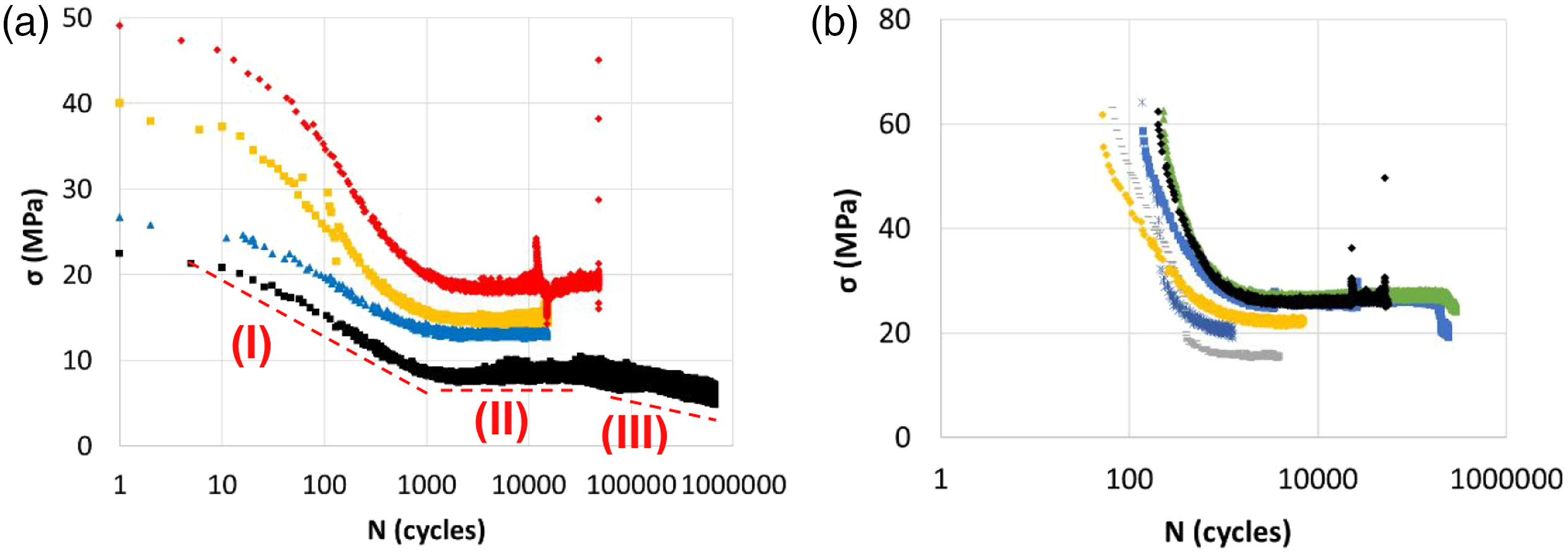
From these curves, one can observe that for high loading amplitudes, the dynamic modulus decreases rapidly in a linear regime of the logarithmic curve until the failure of the specimen. For low applied amplitudes, the dynamic modulus exhibit three decreasing regimes a rapid one during the initial cycles (I), followed by a gradual one (II), and finally a drastic decrease (III) just before the fracture. One can note that the significant damage kinetic in the case of CF-PA6 reinforced with continuous glass fiber (Onyx+GF).
Varying the loading conditions in terms of amplitude, the fatigue behavior of CF-PA6 and CF-PA6 reinforced with continuous glass fiber induces self-heating. This phenomenon influences the viscous behavior of the polymer as a function of the temperature rise level concerning material transition temperatures. In the case of CF-PA6 samples, for the test performed at 10 Hz, the temperature increases up to 60°C (Figure 11). This temperature corresponds to the glass transition zone. At this stage, the polymer stiffness slightly decreases as shown in Figure 5. Therefore, the polymer matrix is subjected to extraordinary thermally activated modifications of its physical state. Maximum induced temperature evolution versus the number of cycles.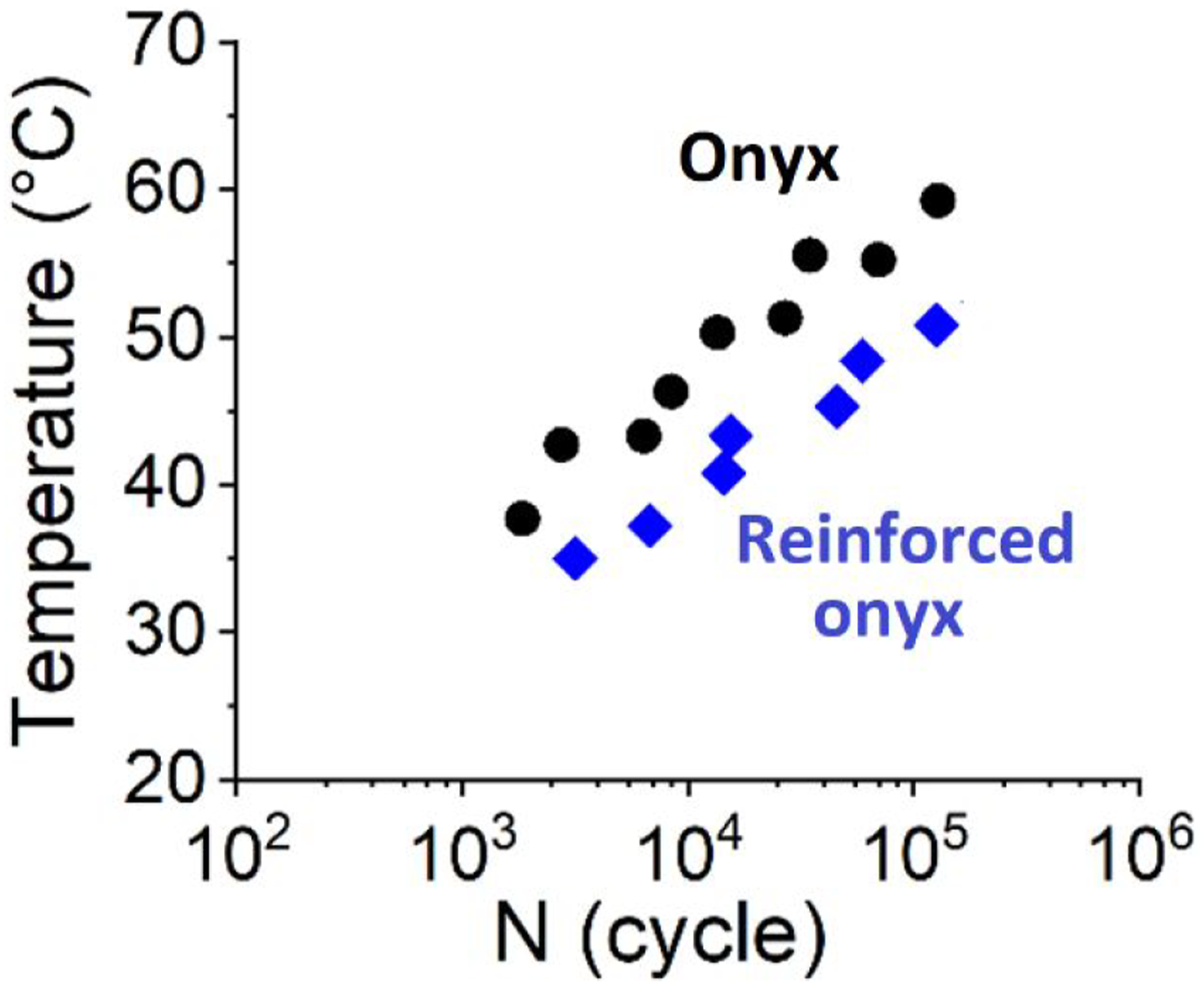
Hence, at the microscopic scale, the fatigue behavior and failure of printed CF-PA6 samples are not only due to the devolvement of diffuse damage but also to the evolution of the viscous behavior of the polymer and the inherent brittle–ductile transition. The evolution of temperature is one of the critical parameters in fatigue. Maximum induced temperature can be a factor in predicting the fatigue behavior of CF-PA6 and reinforced CF-PA6 with continuous glass fiber and the state of polymer in terms of ductility. Figure 11, illustrates the maximum induced temperature just before failure. Figure 11, presents the influence of reinforcement on the maximum induced temperature.
One can observe the same slope of the curve for two cases. As was mentioned, there are two types of fatigue: MF and ITF. By considering the glass transition temperature of about 61°C, the critical fatigue tests with induced thermal fatigue can be separated. Moreover, one can note that the induced temperature for all applied strains is higher in the case of CF-PA6 (without continuous reinforcement).
Fatigue fracture surface
For emphasizing the effect of loading amplitude at a microscopic scale fracture, surface observations have been performed. Figure 12, compares the fracture surfaces of the printed CF-PA6 and CF-PA6 reinforced with continuous glass fiber samples. SEM analysis highlights these conclusions: • For the printed CF-PA6 samples, the first observed damage phenomenon corresponds to the debonding of the filament. This leads to the propagation of interphase cracking. For a higher value of cycles, this damage mechanism is spreading through the whole observation zone (Figure 12(a)). • The fracture surface observation in the case of CF-PA6 reinforced with continuous glass fiber samples, showed that the bundles of fibers are pulled out from CF-PA6 simultaneously with breakage of the more surrounding matrix (Figure 12(b)). Fracture surface observations for CF-PA6 (a), and CF-PA6 reinforced with continuous glass fiber (b) samples.

Conclusion
In the present work, polymer-based composites using Fused Filament Fabrication (FFF) were prepared and submitted to tension and three points bending fatigue loadings. The main conclusion for this paper is as follows: first, the homogeneous distribution of carbon fiber in used Onyx (CF-PA6) filament was observed through the microscopy observation. The printed CF-PA6 samples in solid infill pattern, have excellent stiffness and mechanical properties under tension. In fatigue, the effect of reinforcement has been analyzed. The results showed that the induced temperature is increased and as a result, the fatigue life is decreased for and reinforced CF6.51-PA6. This phenomenon, which is known as self-heating, can evaluate the viscous behavior of the polymer especially in the glass transition zone (about 60°C). Therefore, it is necessary to study the viscoelastic behavior of CF-PA6. Perez model could predict the viscoelastic behavior of CF-PA6 and CF-PA6 reinforced with continuous glass fiber. Finally, damage mechanisms development in fatigue has been investigated at the microscopic scale. For CF-PA6 and reinforced CF-PA6 with continuous glass fiber, the first observed damage phenomenon corresponds to the debonding of the filaments which leads to the propagation of cracking.
Footnotes
Declaration of conflicting interests
The author(s) declared no potential conflicts of interest with respect to the research, authorship, and/or publication of this article.
Funding
The author(s) received no financial support for the research, authorship, and/or publication of this article.