
Abstract
Nowadays, composite tubes have a wide range of applications in industries. Composite tubes are appropriate alternatives for metal energy absorbers. In this investigation, aluminum-composite tubes are made using Filament Winding (FW) and hand lay-up methods. Carbon Fiber (CF) and Glass Fiber (GF) are used in the FW method, and for the hand lay-up method, glass cloth is used. Five samples were fabricated with different stacking sequences, specimens with one, two, and three glass layers, one carbon layer, and hybrid carbon/glass layers. Characterization is performed by Scanning Electron Microscopy (SEM) analysis and mechanical tests (bending, compressive, and fatigue). The maximum bending force in the triple-layer GF tube is higher than other samples, while the maximum compressive force is observed in the hybrid carbon and GF tube. On the other hand, the fatigue strength of single-layer CF tubes is higher than single-layer GF tubes, so that the fracture cycles of single-layer CF tubes (600597) is significantly more than that of single-layer GF tubes (470068) at the force of 35 N. In addition, the compressive and bending energies absorption of samples were calculated. The hybrid carbon and GF tube absorbed higher energy than other samples. In GF and CF hybrid tubes, failure did not occur suddenly but gradually. This appropriate failure mechanism in the hybrid tube resulted in higher energy absorption and made it a suitable choice for industrial applications.
Introduction
Since early 1970, thin-walled tubes have been growing due to the increased safety-conscious environment in the major transportation industry such as airlines, aerospace, and automotive. Therefore, thin-walled structures in the aviation industry have majorly been applied as steering columns, webbed fuselage structures, and landing gears for helicopters. 1
Polymer-based Carbon Fiber (CF) and Glass fiber (GF) composites are consumed by space industries and defense sectors due to their high strength to weight ratio, dimensional stability, high heat and chemical resistance, reusability, and thermal stability . 2
Epoxy is usually applied as a matrix in the composites used for covering thin-walled metal tubes, and GF or CF are used as reinforcement. The method of making these composite tubes is different. Pultrusion and Filament Winding (FW) methods are used to make composite tubes. 1 Pultrusion, pull winding, and pull braiding processes can manufacture the fiber-reinforced pipe of high length. The composite pipes usually include metal layers to resist the high tensile and external buckling loads. 3 Huang 4 and Liu 5 performed experiments on thin-walled aluminum and steel tubes with the rectangular and circular cross-sections subjected to bending load. In this study, the effect of cylindrical indentor on the bending strength of these tubes was investigated.
Stefanoska et al. , 6 Shin et al. , 7 and Saggar 8 reported the properties of epoxy resin/fiberglass and epoxy resin/CF composite tubes under a three-point bending load produced by the FW method. Khalid et al. 9 and Kaynak 10 studied the fatigue behavior of epoxy/fiberglass composite tubes by using the FW method, the aluminum shaft tubes were covered with a composite layer of epoxy/fiberglass resin. Effect of fiber orientation, fiber tension, and winding speed in composite tubes by FW method was investigated as effective parameters on the properties by Metodiva et al. 11
Eksi 12,13 and Jung et al. 14 investigated the bending properties of aluminum-composite tubes using the hand lay-up method. Although these tubes reduced displacement at the fracture point, they resisted more loads with increasing thickness. Liu et al. 15 investigated the bending properties of tubes. When tubes are subjected to bending loading, cracks begin in the outer layer. Because of the increase in load, the stress becomes critical, resulting in an unstable crack. Critical cracking is related to the tear of the fibers and the matrix, and when the crack becomes critical, the fibers crack.
Khalid et al. 9 investigated aluminum-composite tubes subjected to bending-fatigue loading and concluded that composite tubes have a higher strength to weight ratio due to increased thickness and have higher fatigue resistance. Because of the repetition of the applied load, crack propagation and failure occurred.
Many studies have been done on composite pipes’ mechanical and physical properties, reinforced with various fibers and resins, some examples of which are described below.
The tensile strength, mechanical properties, and hardness of composite pipes in various conditions such as seawater have been investigated by Gunoz et al. .16,17 The effect of hydrothermal aging on the mechanical properties of composite pipes reinforced by CF and basalt fiber with epoxy resin has been investigated .18–20
This research aims to evaluate and compare behavior and fracture mechanisms of thin-walled aluminum-composite tubes under bending, compressive, fatigue tests. Moreover, in this study, CF, GF, and GF fabrics are wound around the aluminum tube by FW and hand lay-up methods. These composite tubes' fracture mechanism and maximum force with wound filament are compared and investigated using visual evaluations and SEM analysis.
Experimental methods
Materials
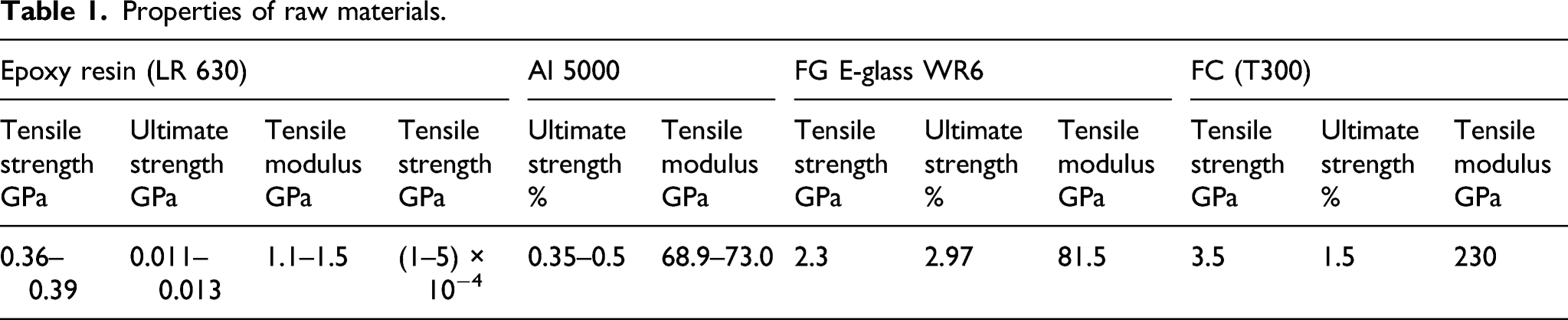
The materials used in this research are as follows: aluminum tube grade of 5000 with 16 mm internal diameter, 18 mm external diameter, 1 mm thickness, and 200 mm length. Low viscosity epoxy resin (LR630) was purchased from Huntsman Co., with a viscosity of 1000–1500 cps, density 1.17 g/cm3. GF is E-glass WR6, Tex 2400, 17 μm filament diameter, tensile strength 2306 MPa, tensile modulus 81.5 GPa, and fracture strain 2.97%. CF is Toray T300, 3K, 7 μm filament diameter, 1.76 g/cm3 density, tensile strength 3530 MPa, tensile modulus 230 GPa, and fracture strain 1.5%. The GF fabric is a woven E-glass fabric with 300gr/m2 areal density.
Composite preparation
In this research, the aluminum lining tube is covered with composite by two methods: FW and hand lay-up (Figure 1). The sample specifications are according to Table 1. Schematic of manufacturing processes. Properties of raw materials.
FW
At first, the aluminum tubes were polished by rough sand grit to increase the resin and aluminum interface’s mechanical bonding. Afterward, the tube surface was washed with acetone to remove any contaminations and waxes. The mandrel was from an iron bar. Next, the fibers have been impregnated by the resin mixture to harden by a 2/1 ratio.
Winding angle
The fibers were wound by 25°, which is an optimum degree for achieving the highest strength. There are many research types on the effect of winding angle on tubular composites' mechanical properties.21–23 Based on the research of Natsuki, 21 the best angle for FW should be between 0° to 30°. In this range, the stress in the fiber direction has the highest value, and the stress in the transverse direction has the lowest value. However, on the angles upper than 45°, the shear resistance of the tube is higher. On the less winding angle, the more fibers orient along the tube length. Thereby the maximum stress is tolerated by the fibers, and bending stress increases. When the angle increases, the fibers orient along the radial direction; thereby, the tensile stress is majorly tolerated by the matrix with low tensile strength. Regarding the importance of tensile strength and shear resistance in the bending test, this research’s selected angle is 25°.
Hand lay-up method
The hand lay-up was performed only for E-glass cloth. The aluminum tube surfaces were polished by sand grit to increase mechanical bonding in the tube and cloth interface. Next, the tube surface was washed with acetone. Afterward, the GF cloth was thoroughly impregnated by the epoxy resin mixture and 50% harder. Next, the GF cloth slowly was wound around the aluminum tube to achieve the appropriate thickness. The curing was completed at an environment temperature. The specification of samples has been introduced in Table 1.
In this paper, except for the inertia of moment calculations, the effect of slight differences in tube thickness on properties is ignored.
Analyses
Scanning electron microscope
The fracture surface was analyzed by Scanning Electron Microscope (SEM) from Japan HIT4160 02 Company located in Tehran University. Before analysis, the samples were coated with a thin layer of gold.
Compressive test
In this test, the sample length, 10 mm, the constant pressing force 1 kN, loading rate 5 mm/min, and displacement value were considered 12 mm. The test setup is based on ASTM D348. 24
Fourteen tubes were tested with three repeats. The displacement value of all tubes was 12 mm. The results of compressive tests have been shown in Figures 2–4. Two aluminum tubes were tested as a comparison with other tubes. The load-displacement curve of the aluminum-composite tube from the axial crushing test results. Deformed shape of the tube at 12 mm displacement. SEM analysis of composite samples: (a) Al-composite tube with double-layer GFs (b) Al-composite tube with double-layer GF and CFs as hybrid fiber (c) Al-composite tube with glass cloth (e) Al-composite tube with single-layer CF (f)Aluminum-composite tube with single-layer CF. Failure modes of observed Al-composite tubes from the compressive test: (a) All of the samples (b) Al tube covered with GF fabric cloth (c) Al tube covered double-layer of GF and CF as hybrid fiber (d) Al tube covered with triple-layer GF (e) Al tube covered with double-layer of GF (f) Al tube.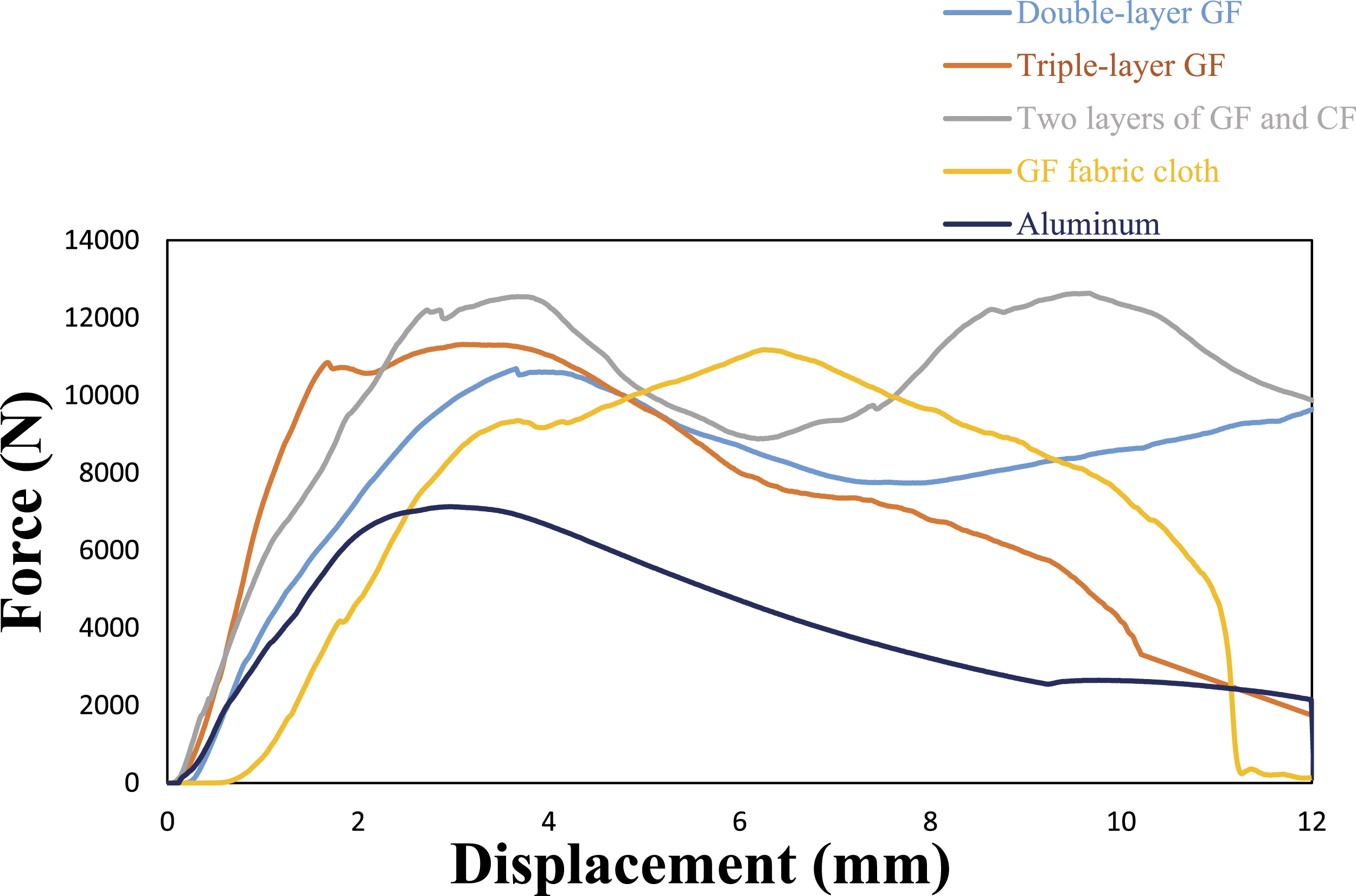


Three-point bending test
The setup of the three-point bending test is based on ASTM D790.
6
The span length 160 mm, constant loading force 1 kN, loading rate 2 mm/min, and displacement value were selected 50 mm. The stiffness value in bending and compressive tests have been determined from the slope of the linear region in force-displacement curves. The results of bending tests are shown in Figures 5 and 6. The load-displacement curve of the aluminum-composite tube from the bending collapsing test results. Deformed shape of the tube at 50 mm displacement. Deformed shapes of Al-composite specimen under three-point bending test: (a) All of the samples (b) Al tube covered with GF fabric cloth (c) Al tube covered with triple-layer GF (d) Al tube covered with double-layer GF (e) Al tube covered with single-layer GF (f) Al tube covered double-layer of GF and CF as hybrid fiber (g) Al tube covered with single-layer CF.

Fatigue test
Under applying fatigue loading, seven tubes from three kinds of material (aluminum, single-layer GF aluminum-composite, and double-layers CF aluminum-composite tube) are subjected to bending-fatigue load by forces of 6, 30, and 35 N. The aluminum tube was loaded with a force of only 35 N, and two other tubes were tested with forces of 6, 30, and 35 (35 N with two repetitions).
The bending type of fatigue test is performed by the rotation frequency of 50 Hz. The cycles were continued to the fracture point. The testing apparatus model was SANTAM Co., and the test setup was based on ASTM D7774 .
6
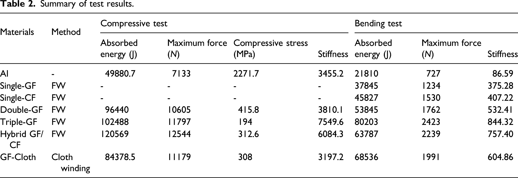
The results of bending tests have been shown in Figures 3 and 7, and Table 2. Samples of hybrid Al-composite resulted from the bending-fatigue test: (a) All of the samples (b) Al tube with a force of 35 N (c) Al tube covered with single-layer CF with a force of 30 N (d) Al tube covered with single-layer GF with a force of 30 N (e) Al tube covered with single-layer CF with a force of 35 N (f) Al tube covered with single-layer GF with a force of 35 N. Summary of test results.
Energy absorption test
Values of energy absorption equal to the area under the force-displacement curve were computed by software. The results were reported in the following section.
Results and discussion
Compressive test
General results of comparing these five tubes, according to Figure 2 can be concluded that the compressive force of hybrid aluminum-composite tubes is higher than other tubes. Triple-layers aluminum-composite sample has been tolerated by compressive force because there is a higher thickness than a double-layer. Although the thickness of the hybrid sample is lower than a triple-layer sample, its compressive force is higher than that of the triple-layer sample. The existence of a carbon layer in the hybrid sample can even compensate for the effect of thickness. The compressive force of the glass cloth winding aluminum-composite tube is higher than whole samples because of the higher thickness and woven perpendicular fiber (weft fibers). The cloth-winded sample can leave defects to include thickness changes in the length of tube, delamination, and remained bubbles between lower layers than in FW methods.
Table 2 shows the maximum compressive force of double-layer GF composite 1.48 time, triple-layer GF composite 2.31 time, two layers GF and CF composite 1.75 times, and GF fabric cloth composite 1.56 time higher than pure aluminum tube.
Figure 3 (a) is related to the compressive test. It can be seen that fiberglass was opened and bent in the tube’s inner and outer direction. There is a split in the center, and some fibers have been fragmented and located into this split.
Figure 3 (b) is related to the hybrid tube of the compressive test. By applying load on the tube’s cross-section, the CF was opened, a lot of curvatures formed; due to the flexibility of CF and high modulus, it was not fractured at all. GF bent over CF in some tube regions, and two fibers were twisted together in other regions. Due to twisting fibers, the CF and GF in their interface are not observable. Figure 3 (c) is related to the glass cloth by hand lay-up method around the aluminum tube. The cross-section of aluminum and composite and interface of two tubes can be observed. Due to the manual method and lack of proper wettability, a definite separation was created between tube and cloth. It was ruptured and delaminated due to wear with a pressing punch plate. In Figure 3 (d), the compressive test by applying a load, glass cloth, unlike the carbon and GF tubes samples, was not bent to inward and outward of the tube. It was subjected to shearing forces and fragmented. Matrix fracture and delamination in black regions are apparent.
Figure 3 (e) is related to tube’s cross-section in a sample of Single-GF. In the fatigue test and by applying a load, transversal and longitudinal cracks at the GF and delamination among above and below layers were created. Tearing and fiber split also is observable in the central area. The distance of the split was measured at 103 μm. Figure 3 (f) demonstrates delamination, wear, tearing, and transversal cracks, and it also shows to separate interface of aluminum with CF.
Today, four failure modes due to compressive loading of composite specimens are classified and investigated: (1) Lamina bending/fiber splaying crushing mode. (2) Fragmentation/transverse shearing crushing mode. (3) Brittle failure. (4) Folding/local buckling/accordion/concertina Crushing mode.
Lamina bending/Fiber splaying crushing mode
Because of cracks in the direction of the fibers and between the laminates, a separation is created, called fronds. These fronds bend inwards and outwards in the tube’s thickness and have different radius curvatures that depend on the fibers and matrix’s loading and properties. As a result, a gap is created in the center of the thickness of the fiber.
Fragmentation/transverse shearing crushing mode
Shear and compressive stresses and failure are created in the tube’s direction, then fragmentation, delamination, and tearing mode between layers are formed.
Brittle failure
Brittle failure is a combination of fragmenting and opening in fibers. In fronds mode, the longitudinal cracks are created in the center of the thickness of specimen. Because of compressive stresses, the gap between the fronds increase, and the fibrous material comes in powder form in this gap.
Folding/local buckling/accordion/concertina Crushing mode
For non-brittle composite materials, this mode of failure occurs. It rarely occurs for brittle materials, or if it does, the matrix must have a yield strength. 24
Figure 4 demonstrates failure modes of the compressive test. Figure 4 (a) shows all of the samples in the compressive test. Figure 4 (b) is an Al tube covered with GF fabric cloth. In loading, glass cloth resulted in wear and fragmentation, and aluminum tube formed in local buckling during plastic deformation. In general, regarding Figures 2–4, these cases can be concluded: one- high-compressive strength CF and GF hybrid aluminum-composite tubes, two- Improving behavior of failure of CF and GF hybrid aluminum-composite tubes, and three- high energy absorption of CF and GF hybrid aluminum-composite tubes and consequently these tubes can be utilized in various industries as a suggested material.
Figure 4 (c) shows the carbon and glass hybrid fibers aluminum-composite tube under compressive load. Based on the article of, 15 failure did not occur suddenly. Because in the beginning, the fracture was created in the CF, and with complete failure, the force is transferred to the GFs, and two fibers failed.
Figures 4(d) and (e) demonstrates a cross-section of aluminum-composite GF tubes with three layers and two layers under compressive loading, respectively. Different cracks have been created on the cross-section and length of tubes under applying compressive loading on the cross-section of these tubes. Many cracks were created in the center of the thickness of these tubes. As a result, the fibers opened and bent inward and outward of the tube. Abrasion occurs due to the mandrel’s wear with the fibers, which shear and transverse cracks were created in the fibers. Eventually, a small number of fibers became powder and spilled out. Splitting and separation between fibers are observed in other areas, especially in those bent outwards. The aluminum tube’s existence inside the composite coating causes a plastic deformation, and local buckling was created inside these tubes. This deformation in the tube prevented brittle and sudden failure, and also, the stress–strain diagram went up. In the aluminum-composite tube with GF applying the load, delamination, fiber wear, and separation of the aluminum-composite interface were formed in compressive load.
On the other hand, aluminum tubes played a significant role in the reduction of sudden failure. Aluminum metal has high flexibility, so, in loading, it was buckled. As a result, defects such as cracks and delamination in the tube were formed very small.
Figure 4 (f) shows the aluminum tube after the compressive test.
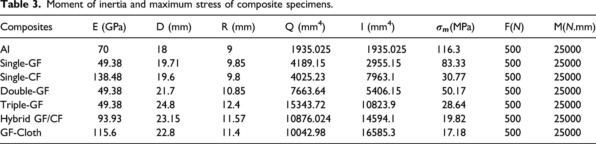
Moment of inertia
Moment of inertia and maximum stress of composite specimens.
To make samples with FW and hand lay-up (which is done manually), the amount of resin and reinforcement differs, so the rule of mixtures for FW and hand lay-up are different. The relation of the rule of mixtures for the FW and hand lay-up is given in equations (1) and (2), respectively

Ec, Ef, and Ep are the modulus of elasticity of composite, reinforcement, and polymer, respectively.
According to the above equations and data in Table 3, the elastic modulus of each composite is calculated. Equation (3) is used to calculate the moment of inertia of pipes
25

In the equation above, D is the outer diameter, and d is the inner diameter of the pipe. The inner diameter for all samples is 16 mm, and the values of the outer diameter of the pipes after the FW are given in Table 3.
To calculate the moment of inertia of composite/aluminum tube, a method is used to transform the beam’s section into one made of a single material. Using this transform factor is that all of the calculated moment inertia are converted to the aluminum moment of inertia to be comparable. The moment of inertia can be calculated from Equation
25

After calculating the moment of inertia, the maximum stress that each sample can withstand can be calculated using equation (5)
25

σ m = Maximum stress (MPa)
F = Maximum force (N)
L = distance between the two supports = 200 mm
M = bending moment = FL/4 (N mm)
R = external radius of the pipe + the thickness of composite with aluminum (mm)
I: Moment of inertia (mm4)
The point to note is that all of the above relationships are true in the elastic region. According to the data in Table 3, it can be seen that with increasing thickness, the moment of inertia has increased. Increasing the moment of inertia reduces the stress on the sample.
According to Table 3, it can be seen that maximum stress in the bare aluminum tube is higher than in other samples, which means that FW has increased the life of these tubes. For tubes covered with FG, a downward trend in maximum stress with increasing layer thickness has occurred.
According to the data reported in Table 3, it can be concluded that with increasing composite thickness, the moment of inertia has increased. When the applied force is equal for all samples, increasing the moment of inertia reduces the stress on the sample. As a result, the maximum stress in the bare aluminum tube is higher than in other samples, which means that winding composite layers can increase the durability of these tubes.
Consequently, for tubes covered with GF, the moment of inertia increases by increasing the layers. In these tubes, a downward trend in maximum bending stress with increasing GF layers thickness has occurred. CF reinforced aluminum tubes can withstand more stress than GF reinforced tubes due to the high strength of carbon fibers. As indicated in Table 3, the moment of inertia for a hybrid glass/carbon fiber wound tube is about three times of a double glass fiber wound tube. The hybridization of glass and carbon fiber cause a positive effect and increase the maximum bending stress over double-layer GF.
Bending test
General results in Figure 5 show that bending force increases with increasing thickness in the fibers and tubes. In addition, the single-layer carbon tube’s bending maximum force is higher than that of glass single-layer. In GF/CF hybrid tubes, the maximum bending force is higher than that of double-GF tubes because single-layer CF has a higher tensile strength than fiberglass. As a result, hybrid GF/CF tubes can be used to improve bending properties. As expected, according to Table 2, the value of the failure displacement of hybrid composite is lower than the double-layers GF.
According to Table 2, it is observed that the tubes covered by single-layer CF composite have higher stiffness, absorbed energy (surface area below the curve), and maximum force than those of tubes covered by single-layer GF composite.
In winding cloth (hand lay-up), many defects are formed in the tubes when they are subjected to bending load due to making these tubes by hand. It can be concluded that it has more defects than FW. The fabrics have a two-dimensional orientation (the angles of 0° and 90°), increasing the maximum bending force. The same comparison can be seen in the hybridization of composite coatings. The hybrid composite causes an increase in the ultimate maximum force, absorbed energy, and reduces the failure strain compared to the double-layer fiberglass. Based on the above description, the stiffness and maximum force of the CF tube are higher than GF tube. Thus, the maximum bending force of hybrid tubes is higher than pure fiberglass. Since epoxy composite with GF and CF is brittle, it does not accept much deformation until it fails.
According to Table 2, the maximum bending force of single-layer GF composite 1.7 times, double-layer GF composite 2.4 times, triple-layer GF composite 3.3 time, single-layer CF composite 2.1 time, two layers GF and CF composite 3.08 time, and GF fabric cloth composite 2.7 time higher than the pure aluminum tube. In Figure 6, the bending test results in thin-walled aluminum and aluminum-composite tubes can be seen. Figure 6 (a) shows all of the samples, and in Figure 6 (b) can be seen that the fabric cloth when they were subjected to bending load, many defects were created in these tubes because those were made by manual fabric method. There are several defects in the samples made by this method: the high number of cracks, separation of the cloth from the matrix, separation of the cloth from the aluminum tube, and excess moisture and remained in the matrix.
Figure 6(c)–(e) is related to single-layer, double-layer, and triple-layer GF composites, respectively. During loading, some defects have been created on the samples indicated by arrows. In initial loading, longitudinal and transverse cracks were created in the lower part of the tube, and with increasing force, cracks grew, and fibers pulled from the tube out, which is called local buckling or hinging. In white areas, delamination or separation of the fibers and the matrix is observed. On the other hand, by hybridizing the composite coating, the ultimate maximum force, absorbed energy, and fracture displacement of the tubes increase. It should be pointed out that the characteristics of the interface between the layers and the excellent adhesion between the hybrid layers can play a crucial role in the mechanical properties of the hybrid coatings, and it is shown in Figure 6 (f).
Figure 6 (g) shows an Al tube covered with single-layer CF. Tubes coated with single-layer CF composite have high stiffness, absorbed energy (surface below the curve), bending maximum force.
Fatigue test
In general, from the fatigue result, it can be concluded that the single-layer CF aluminum-composite tube has more resistance than the single-layer GF aluminum-composite tube due to its high strength to weight ratio, flexibility, stiffness, and lower defects.
There was no failure in composite tubes during loading by force of 6 N due to lack of sufficient force. Thus, it was not included in Figure 7.
Figure 7 demonstrates failed tubes in bending-fatigue load. Figure 7 (a) shows all of the samples in the fatigue test.
Results of fatigue loading test of composites samples.

Figure 7 (c) aluminum-composite tube with single-layer CF, with a force of 30 N and a frequency of 50 Hz, was not failed, and the number of cycles of 83576 was obtained (Table 4). In summary, firstly, small cracks were created in the matrix due to the initial loading. After increasing the number of cycles, the separation of the interface of aluminum and composite was created. The CF has failed in the middle of the tube’s length, but no fracture occurred in the aluminum tube.
In Figure 7 (d), the aluminum-composite tube’s cross-section with single-layer GFs, with a force of 30 N and a frequency of 50 Hz, can be seen. The tube did not fail and was only created a separation between the aluminum and composite layer. Finally, the number of 56723 cycles was obtained (Table 4).
Figure 7 (e) is relevant to the aluminum-composite tube with single-layer CF by force of 35 N and 50 Hz frequency. As a result, it failed with the number of cycles 600597 (Table 4). At the beginning of the initial loading, the matrix formed a few cracks. By increasing the number of cycles, crack passed them through matrix and fiber due to flexibility and high stiffness. As the number of cycles increased, it affected aluminum, by continuing this process, many cracks were formed in aluminum, and eventually, the tube failed.
Meanwhile, cracks were formed along of fiber and along the tube transversely. Aluminum-composite tube with single-layer CF was examined by force of repetition 35 N. Despite passing 5 days in the fatigue load and applying 10,278,199 cycles with the same constant frequency of 50 Hz, any crack and fracture did not occur (Table 4).
Figure 7 (f) aluminum-composite tube with single-layer GF was subjected to the load of 35 N and frequency of 50 Hz resulted in 470068 cycles (Table 4). The tube’s fracture mechanism is as follows: at the beginning, in initial loading, the matrix has formed a split then by increasing the number of cycles, due to being GF brittle, short cracks in GF has grown, and then the fiber pulled the matrix out. As the continuation of loading increase, the fiber was separated from the matrix, delamination was formed obviously, and finally, the crack propagation increased widely until the ultimate failure took place.
Absorbed energy
The total absorbed energy is equal to the surface area under the load-displacement curve .
26
The real work or absorbed energy can be related to either progressive crushing or folding in crushing under static or dynamic compression. For determining the area under the curve, can use the following formula
24

F and δ are the crushing force and crush distance, respectively. Farley et al. 26 have been worked on hybrid composites. Table 1 compares the absorbed energy of different tubes together. It can be seen that hybrid GF/CF and triple-GF have the highest absorption energy compared to other samples (120 and 102 kJ, respectively).
A comparison between energy absorption in bending and compressive tests
According to Table 2 the bending energy absorption of single-layer GF composite is 1.70 times, double-layer GF composite 2.46 time, triple-layer GF composite 3.67 times, single-layer CF composite 2.1 time, two layers GF and CF composite 2.92 times, and GF fabric cloth composite 3.1 time higher than the pure aluminum tube.
Based on Table 2 the compressive energy absorption of double-layer GF composite 1.93 times, triple-layer GF composite 2.05 time, two layers GF and CF composite 2.41 time, and GF fabric cloth composite 1.69 times higher than the pure aluminum tube.
As a result, despite being two layers GF and CF composite in the hybrid sample, its energy absorption is more than double-layer GF and triple-layer GF composite. Thus, it can absorb a large amount of energy when subjected to bending and compressive loads.
Conclusions
(1) In the bending test, the aluminum-composite tube with GFs and double-layer carbon, because of hybridizing CF and GF together and high bending maximum force 5539 N compared to other materials, is more suitable. (2) In the compression test, the aluminum-composite tube with GFs and double-layer carbon, due to high maximum force 15641 N and high energy absorption during loading, indicates that the material is more suitable than the other materials tested. (3) In the fatigue test, the aluminum-composite tube with CF, because of its higher strength to weight ratio and higher stiffness of CF than glass, resists more cycles with the same force and frequency, indicate that the carbon-aluminum-fiber composite tube has more strong than fiberglass.
Footnotes
Acknowledgments
We wish to express our appreciation to Dr M. Karimi and Dr Nazari from Shahrood University of technology for their kindly aids.
Declaration of conflicting interests
The author(s) declared no potential conflicts of interest with respect to the research, authorship, and/or publication of this article.
Funding
The author(s) received no financial support for the research, authorship, and/or publication of this article.