
Abstract
Hybrid laminates consisting of C-glass woven fabric/epoxy composite plies and 3k-carbon woven fabric/epoxy composite plies are studied for fatigue damage and residual strength. Tension–tension fatigue tests were conducted on notched composite laminates at two load ratios of 0.1 and 0.25. The laminates were fabricated with the hand lay-up process for a symmetrical stacking sequence [0/90]3s made of three 3k-carbon/epoxy composite plies at both top and bottom sections and six C-glass/epoxy composite plies in the middle. Fatigue damage was generated on notched specimens with 4 × 10⁴ load cycles to damage for residual strength tests. The hybridization was found to be beneficial for relative damage sensitivity under one of four different fatigue conditions although its effect was marginal while three other conditions were not in favor. A relative damage sensitivity factor expression (or a criterion) was developed for quantitative comparisons between non-hybrid and hybrid composites and was theoretically demonstrated to be valid for any possible cases where various combinations are possible due to differences in strength reduction rate between two different composite systems. A theoretical framework with the relative damage sensitivity factor is proposed as a guide to deal with the complexity involving uncertainties and a large number of variables in the hybrid composite system. New damage mechanisms of the hybrid system due to dissimilarity between two sub-composite systems (i.e. glass/epoxy and carbon/epoxy) were hypothesized and tested to be valid with evidence based on microscopic and macroscopic examinations. The difference between static and fatigue damage is discussed.
Keywords
Introduction
Composite material is a structure made out of at least two dissimilar elements working together to produce material properties that are different from the properties of those elements on their own. Fiber reinforced plastics (FRP) composite materials consist of a reinforcement of some kind and a matrix. They have been widely used as laminates in the aerospace industry and to a lesser extent in the automotive industry. Numerous research studies have been conducted to improve the behavior of composites under various loading conditions. They have shown that the composites made of one type of fiber reinforcement can be further improved by hybridizing for the optimum performance [1,2]. The hybrid laminates may be designed with two or more different types of fiber reinforcement. They can be made of transversely isotropic laminates if longitudinal as well as lateral mechanical performances are required [2,3]. Also, they are useful for the cost reduction of composites, which may be achieved by incorporating laminates of low-cost but high performance fibers in designing hybrid laminates without a significant reduction of the mechanical properties [4]. Hybrid laminates reinforced with glass and carbon fibers have indeed been found to be useful in practice, especially in automotive and aerospace industries [5–7]. An early use of both carbon and glass fibers is traced back to the Ford GT40 racing car body and structural skin of the rotor blades in the Aerospatiale SA360 helicopter [8]. The recent structural applications of hybrid composites have been even more extended by focusing efforts on energy reduction since the glass and carbon fiber reinforced polymer matrix proved to be significantly effective [9].
As the engineering structures are frequently subjected to fatigue loading, the fatigue analysis plays an important role in the design of structural components. The fatigue in composites has been recognized as a complex phenomenon compared to that of monolithic materials. There have been numerous studies investigating the fatigue performance of glass/epoxy, carbon/epoxy, and their hybrid composites for the effect of cyclic loading on residual properties [10–31]. However, most of them have focused on non-hybrid composites such as unidirectional, multidirectional, and woven fabric composites or focused on fatigue performance only. Ozturk and Moore [27] investigated the tensile fatigue behavior of woven carbon/carbon laminates without notch as a function of stress level and found that, as a result of fatigue loading up to 106 cycles, residual strength and modulus in the on-axis direction were not significantly reduced. Kawai and Taniguchi [28] conducted a similar study on plain-woven carbon/epoxy laminates without notch. They found that the fatigue behavior of the laminates significantly depended on fiber orientation. Pandita et al. [29] and Fujii and Amijima [11] have investigated fatigue behavior of woven glass fabric/polyester laminates and suggested damage mechanisms similar to that of Tanimoto and Amijima [10] who investigated similar laminates with notch.
Yoshioka and Seferis [30,31] conducted tension–tension fatigue tests on two different composite systems consisting of epoxy and phenolic matrices respectively reinforced with plain weave carbon fabric. They found that the residual strength of the epoxy laminates containing a hole after being fatigue damaged for a wide range of load cycles (1500 to 5 × 10⁵) is even higher than undamaged ones. A mechanism responsible for the increase was suggested such that the concentrated stress is relieved around a hole and, as a result, is redistributed due to the fatigue damage. As such, a geometry variation for the stress concentration has been found to be another factor affecting the residual strength.
Recently, Allameh Haery et al. [32] studied the effect of hybridization on tensile strength of laminates with a hole and found considerable benefits. This article as continuation of the previous work [32] focuses on the effects of inter-ply hybridization on residual tensile strength after fatigue damage for notched laminates consisting of glass and carbon fiber woven fabrics in epoxy matrix. The main objective is twofold – one was to develop a new theoretical framework for developing hybrid composites and the other was to identify new damage mechanisms of hybrid composites.
A theoretical framework for fatigue damage process
Understanding of the fatigue damage process is important for developing a new composite system. The fatigue damage sequence coupled with a relevant description leading to the final failure is the core of the process for a series of events. Various experimental techniques including in situ and/or post-damage observation using microscopes [33], x-radiography [14], image processing algorithm [19], or c-scan [13] may be useful in conjunction with the post-damage analysis for collecting direct information. However, it is difficult to observe internally hidden in situ damage mechanisms and its behavior at a particular point does not necessarily represent all other points because of the inherent uncertainties originating from various sources such as in-homogeneity in both constituent materials and composite microstructure due to the imperfect composite fabrication technology. For this reason, the post-damage analysis may be also useful for inferences of the damage mechanisms. More importantly, the facts based on the observations are about particular composite systems at a particular moment and therefore not necessarily applicable to other parts of composite system or other composite systems. For wider applications and better understanding, the post-damage analysis requires a theoretical framework for various interpretations and for navigating of collected/processed information towards the applications for improving design, performance, and optimized uses, of the composites in general. Most studies in the literature have focused on a limited number of parameters applicable to particular composites for fatigue damage let alone hybrid composites. Therefore, the following theoretical framework is proposed here for extending usefulness of limited data and observational facts.
The fatigue process of a monolithic material as a constituent of a composite commonly consists of two stages namely crack initiation and propagation prior to the final failure. The crack initiation is affected by a set of properties and is susceptible to the inherent defects in the material while the crack propagation is affected by another set of properties. Further, when different constituent materials are combined for a composite system, the fatigue behavior of a constituent material is affected by other constituent material properties such as stiffness, strength, and relativity between properties of a composite system. The relativity is dependent on how much they are different from each other. The constituent materials as system elements within a composite system constrain each other during the damage process. Also the fatigue damage behavior is affected by the interface conditions (e.g. bonding) between different materials [13]. They are further affected by large-scale design factors such as geometrical variation (e.g. notch) and hybridization. The theoretical stress analysis and failure criteria [34,35] for the geometrical variation may be useful but their applications are limited to the cases of certain geometries prior to the fatigue damage.
When composites are hybridized for inter-plies of a laminate, three or more different constituent materials may be used, e.g. carbon fiber, glass fiber, and epoxy for matrix such as for the current work. For three different constituent materials, the locations of possible fatigue crack initiation points include: (a) matrix, (b) interface between fiber filaments within glass fiber bundle, (c) interface between fiber filaments within carbon fiber bundle, (d) interface between matrix and glass fiber bundle, (e) interface between matrix and carbon fiber bundle, (f) glass fiber filament, (g) carbon fiber filament, (h) cross-over point for meta-delamination for carbon fabric, (i) cross-over point meta-delamination for glass fabric, (j) interface between glass and glass composite plies, (k) interface between carbon and carbon composite plies, and (l) interface between glass and carbon composite plies. Thus, 12 different locations are possible for a crack to initiate and propagate or to link with other crack grown from other locations. A possible location for merging cracks is dependent on its proximity from the first cracking location and on how fast the cracks initiate and propagate although the first cracking likely propagates into a closer location. Accordingly, the number (Nf) of possibilities for different sequential patterns of damage events in terms of, at least, damage initiation locations are given by
Schematic representation of the tensile fatigue damage development in laminated glass composite.

One way to reduce the complexity due to the uncertainty with a large number of possibilities for hybrid composites may be based on the system approach [36]. A hybrid composite is a system consisting of sub-systems. Each sub-system consists of constituent materials as system elements. For example, a GRP laminate is one sub-system consisting of glass fibers and matrix, and a carbon reinforced plastic (CRP) laminate is another sub-system consisting of carbon fibers and matrix, for a hybrid system consisting of CRP and GRP laminates (to be referred to as ‘CGRP hybrid system’). A certain type of loading (e.g. static loading, fatigue loading) or geometry variation (e.g. due to a notch) is an input to the system and damage is an output. If sub-systems are well defined, one of the keys to understanding the hybrid system damage behavior is to find differences between sub-systems. The major differences may be found near or at the near-interface zone between two different sub-composite systems. The reason is that the damage behavior near or at the near-interface zone is influenced by the difference between two sub-composite systems and hence is different from those of sub-composite systems. Another way to reduce the complexity may be to classify the damage patterns according to crack initiation location at least and cracking direction for inferences of mechanisms in relation with expected behavior based on theoretical predictions.
The damage created as a result of fatigue loading may be quantified in terms of stiffness or residual strength [37]. Two sets of constituent material properties for respective pre-and post-fatigue damages may be used as the characteristics of a composite system. The number of possible relative conditions for the initial constituent material properties of interest prior to damage (NE,pr) can be worked out as


Alternatively, if we consider two sub-composite systems collectively instead of constituent materials (i.e. CRP sub-system and GRP sub-system in the current work), a number of different constituent materials (ne) in equation (2) is replaced with a number of different sub-systems, for the number of possible relative conditions (NE,pr). An example relative condition applicable prior to fatigue damage is


Consequently, the total number of possible damage patterns (NT) characterized by crack initiation location, property numbers, and material/sub-system numbers leading to the residual properties is found to be

Accordingly, the total number of relative damage conditions for the hybrid system (NT), in general, is calculated to be 8.949 (=479,001,600 × 3 × 6) when three constituent materials are considered, or it is 5.749 (=479,001,600 × 2 × 6) when two sub-composite systems instead of materials are considered.
Thus, the residual static properties, in general, are the ones obtained under one of the possible relative material property conditions. The possible number of combinations for residual properties after fatigue (NE,po) would be equal to those before fatigue (NE,pr)

If a composite specimen has a stress variation due to a geometrical variation (e.g. notch) under fatigue loading, the initial set of homogenous properties turn into in-homogeneous ones of the specimen as an output as the damage progresses. As a result of damage, the properties at the maximum stress point on a specimen are different from those at any other points. The damage, thus, can be in general characterized by in-homogeneity distribution of resultant material properties at an appropriate scale. A hybrid composite system prior to fatigue damage may be regarded as being homogenous including woven fabric at an appropriate scale, (knowing that a woven fabric is not homogeneous, for example, at a smaller scale because a set of properties at a cross-over point of woven fabric are different from those of other points) but, as the damage progresses, in-homogeneity is created and more and more widely distributed. Such conditions given by equations (3) to (5) or (6) to (8), thus, will be rearranged depending on the location at a specimen. The initial strength following the fatigue damage is then altered for the resultant residual properties for a given geometry condition.
If we choose and consider two particular composite systems for comparing residual properties, we need to define the residual (structural) strength reduction rate or increase rate – one for a conventional composite system (e.g. GRP system) (Ro), and the other for a hybrid composite system (e.g. CGRP hybrid system) as a large new system (Rn) as

It is possible for the two different composite systems i.e. conventional composite system (CCS) and new hybrid system (NHS) to have the following cases as a result of damage:
Case 1: Rn > 1, R0 > 1, Rn > R0 – both CCS and NHS strengthened, Case 2: Rn > 1, R0 > 1, Rn < R0 – both CCS and NHS strengthened, Case 3: Rn > 1, R0 < 1 – NHS strengthened but CCS weakened, Case 4: Rn < 1, R0 > 1 – CCS strengthened but NHS weakened, Case 5: Rn < 1, R0 < 1, Rn < R0 – both two composite systems weakened, and Case 6: Rn < 1, R0 < 1, Rn > R0 – both two composite systems weakened.
For relative damage sensitivity for two different composite systems (CCS and NHS), the following factor, q (this factor will be referred to as ‘relative damage sensitivity factor’) can be found to be applicable for all the possible cases

According to equation (13), q is found as follows: q < 1 for Case 1; q > 1 for Case 2; q < 1 for Case 3; q > 1 for Case 4; q < 1 for Case 5; and q > 1 for Case 6. In general, q approaches one if there is no difference between two different composite systems, or q < 1 if a NHS is less sensitive to damage than CCS, or q > 1 if NHS is more sensitive to damage than CCS. For developing a new composite system, the smaller the q the better. Thus, equation (13) is a generalized criterion indicating a relative damage sensitivity useful for comparing two different composite systems for the same variation of geometry or/and loading condition. Equations (11) to (13) may also be applicable to static cases in the absence of fatigue damage. The difference between static and fatigue damage will be discussed later. If the residual strength (S) is replaced with the residual stiffness, the same principle is applicable for the residual stiffness comparison for two different systems.
Experimental details
Architecture of woven fabric
The architecture of a woven fabric is characterized by the following parameters: inter-crimp length, bundle width at crimp region, crimping length, and bundle thickness. These parameters for plain woven fabric are illustrated in Figure 2. The inter-crimp length is the distance between two neighboring crimps while the crimping length is the one for the undulating region. The bundle width at the crimp is the one for the transverse bundle, and the bundle thickness is the average thickness of the longitudinal (or horizontal) bundles [38]. The characteristic measurements for the architecture of carbon and glass woven fabric are shown in Table 1.
Terminology for architecture of single woven ply given in Table 1. Characteristic measurements for fiber architecture of carbon and glass woven fabric. CV: coefficient of variation; n: number of specimens.

Specimen preparation
Plain weave C-glass fiber fabric and plain weave 3K-carbon fiber fabric were used for fabricating CGRP plies with a matrix of D.E.R. 331 epoxy resin which is uniformly mixed with a Jointmine hardener, type (905-3S), with a 2:1 ratio by weight.
The laminates consisting of 12 plain weave plies were fabricated with the hand lay-up method for both glass reinforced composite (GRP) system as the control and CGRP hybrid system. As illustrated in Figure 3 for the hand lay-up process, a release agent (wax) was applied on the glass to facilitate the removal of the laminate after curing. An elastic frame was placed on the waxed glass to minimize the possible movements of fabric layers during fabrication. Resin was applied to the bottom fabric layer first with hand rollers and brushes, and continued layer by layer until the last one. Entrapped air was removed with rollers to complete the laminates structure. Another waxed sheet of glass was placed on the top of stack. As the last step, a weight of 150 N is applied on the top to press out any excess resin and trapped air.
Sequence in the hand lay-up method for laminate fabrication.
Mechanical properties for C-glass/epoxy and 3k-carbon/epoxy plies – elastic modulus for warp direction (E11), weft direction (E22), Poisson's ratio (v12), shear modulus (G12), ultimate strength for warp direction (σ1 T ) ult , weft direction (σ2 T ) ult , and shear strength (σ12) ult .

A symmetrical stacking sequence, [0/90]3s was chosen for both GRP and CGRP hybrid systems by considering warp as 0° and weft as 90° directions. The specimens, 210 mm long, 40 mm wide, and 3 mm thick, for fatigue tensile tests were cut from 250 × 350 mm2 plates using a CNC tooling machine (Figure 4). A circular hole with a diameter of 5 mm or 10 mm was drilled at the center of each specimen to give a notch effect.
Specimens used for two different hole sizes of 5 mm and 10 mm.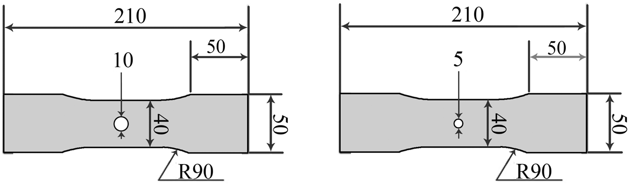
Mechanical testing
The manufactured specimens were loaded for fatigue damage using an Instron 8802 servo-hydraulic testing machine. A constant crosshead speed of 1 mm/min was chosen for the static tensile test at room temperature. For tension–tension fatigue tests, two load ratios (R = minimum load / maximum load), 0.1 and 0.25, with a sinusoidal frequency of 10 Hz, were also chosen. The maximum load for the fatigue was fixed to be a 70% of ultimate tensile load for each composite system (i.e. control GRP and CGRP hybrid). Each fatigue testing was stopped at 4 × 10⁴ cycles for a subsequent static tensile test for measuring the residual strength. The number of cycles (4 × 10⁴) was chosen considering that it is within a range of some beneficial effects which are expected due to the stress redistribution for similar composite systems in Yoshioka and Seferis [31]. At least five specimens were tested for each case.
Damage examination
Fatigue damage was examined using an optical microscope. For all the microscopic examinations, damaged specimens were cut out from a position approximately 10 mm above or below a straight line crossing the minimum ligament section of the specimen to view thickness area surface. Loading of each specimen shown in all the images is in the horizontal direction. The examination was conducted only for CGRP hybrid systems as the previous studies [10,11,29] had already dealt with damage mechanisms for the woven fabric glass/epoxy composite laminates.
Results and discussion
Residual strength prior to fatigue damage
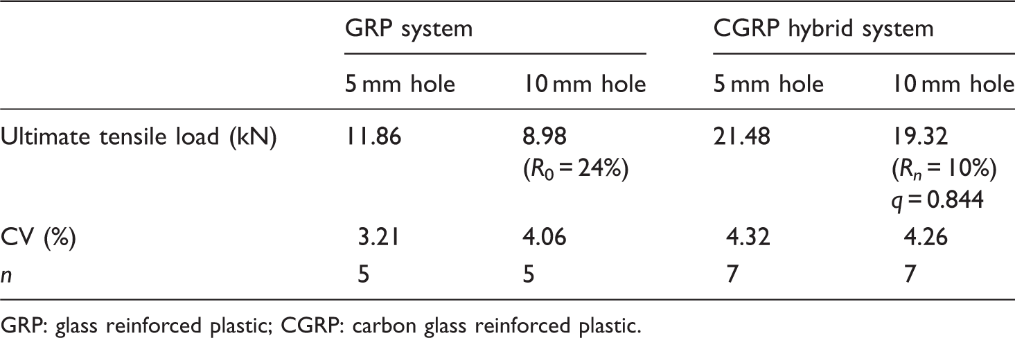
Typical stress–strain curves and data without fatigue damage for control GRP system and CGRP hybrid system obtained previously [32] are shown in Figure 5 and Table 3 respectively as an integral part of the current work. It is seen that the apparent strength decreases as expected with increasing hole size from 5 mm to 10 mm in both GRP and CGRP hybrid systems. The reduction rate (Ro) due to the hole size increase for GRP system (see equation (11) for Typical apparent stress–strain curves for GRP and CGRP hybrid systems for two different hole diameters. The stress is a load divided by maximum cross-sectional area [32]. Average ultimate tensile loads obtained from static tensile tests (without fatigue damage). The reduction rates due to hole size changing from 5 to 10 mm are given in parenthesis. GRP: glass reinforced plastic; CGRP: carbon glass reinforced plastic.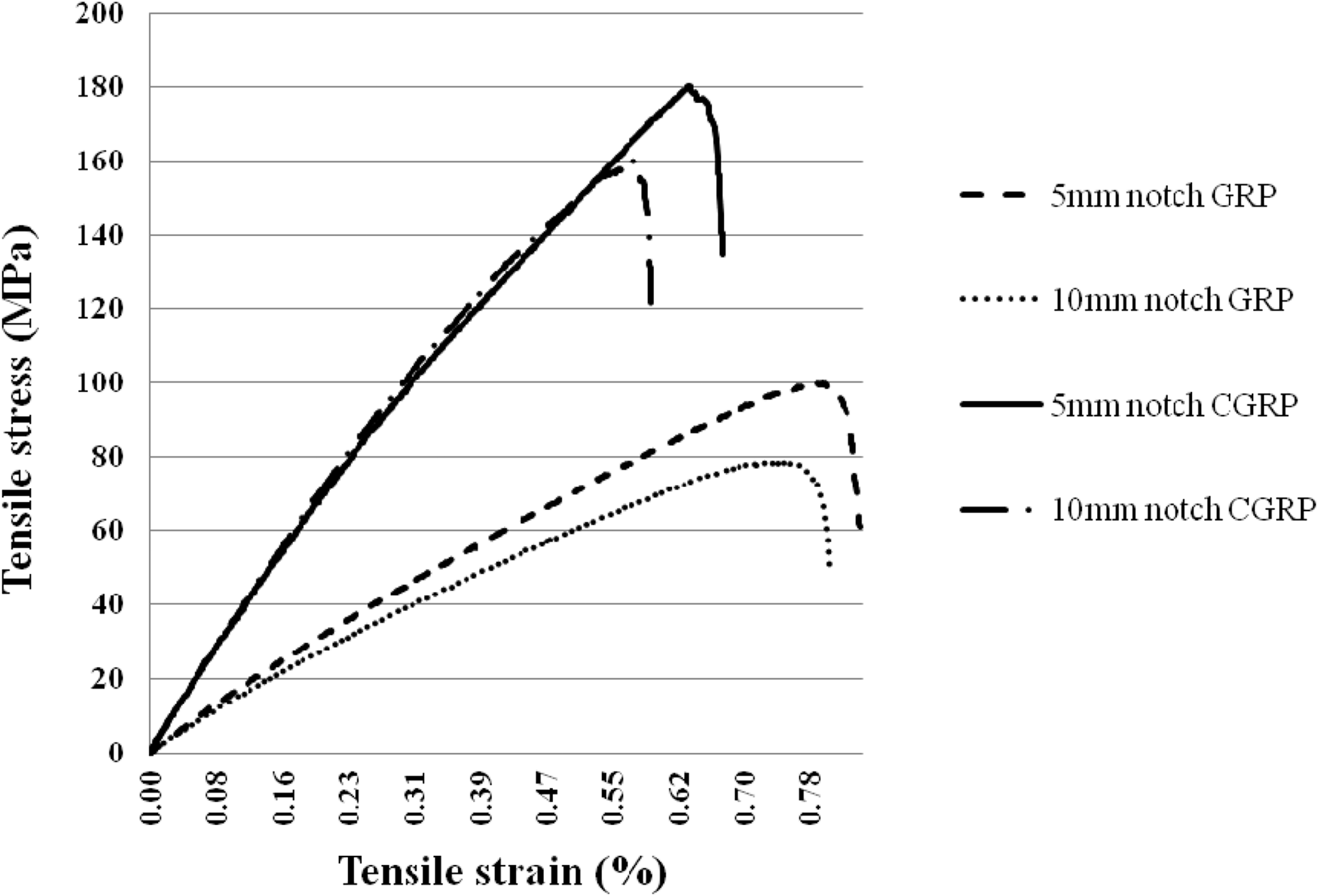
Residual strength after fatigue damage
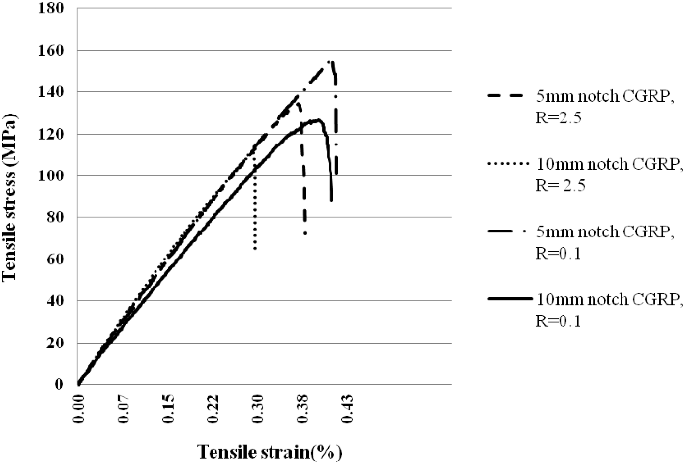
Typical apparent stress–strain curves for GRP and CGRP hybrid systems after being subjected to cyclic loading (4 × 10⁴) are shown in Figures 6 and 7, respectively. Also, a summary of ultimate tensile loads obtained at two different load ratios for two different hole sizes and two different composite systems is given in Table 4. Each value in parenthesis is a reduction rate (Ro or Rn) due to fatigue damage with reference to the corresponding static ultimate load. The load ratios and hole sizes were intended to provide a wide range of different damage conditions.
Typical apparent stress–strain curves for GRP systems for two different hole-diameters after being subjected to 4 × 10⁴ fatigue loading cycles for two different load ratios of 0.1 and 0.25. The stress is a load divided by maximum cross-sectional area. Typical apparent stress–strain curves for CGRP hybrid systems for two different hole-diameters after being subjected to 4 × 10⁴ fatigue loading cycles for two different load ratios of 0.1 and 0.25. The stress is a load divided by maximum cross-sectional area. Average ultimate tensile loads obtained from static tensile tests after being fatigue damaged. The strength reduction rates due to fatigue damage are given in parenthesis. GRP: glass reinforced plastic; CGRP: carbon glass reinforced plastic; CV: coefficient of variation.

Fatigue damage effects on respective composite systems are seen (Table 4) without any strengthening effect from the damage. The residual strength reduction rates (Ro or Rn) at R = 0.25 are higher than those at R = 0.1 despite its smaller fatigue load amplitude at R = 0.25 for two different hole sizes and for both composite systems. The results indicate that the fatigue damage at R = 0.1 is better performed for residual strength than those at R = 0.25. Such a beneficial effect is possible when the local fatigue damage near the hole has relieved a stress concentration as discussed by Yoshioka and Seferis [30,31]. A similar reason to this may be applicable for two different hole sizes – the larger hole size the higher residual strength reduction rate. Also, the stress gradient for a small hole is sharper than that for a large hole near the maximum stress point for a given width of specimen. The damage for 5 mm hole, thus, appears more efficient than 10 mm hole for the stress relief.
When GRP and CGRP hybrid composite systems are compared, the relative damage sensitivity factor (q) values (equation (13)) may be useful. One damage condition with a hole diameter of 0.5 mm and R = 0.1 for CGRP hybrid system is found to be the best for q (=0.995) among the four different damage conditions although CGRP hybrid is only marginally improved (c.f. Case 5 in section ‘A theoretical framework for fatigue damage process’). Otherwise, q is higher than one for all other cases (c.f. Case 6 in the same section).
Damage mechanisms and microscopic examination for CGRP hybrid systems
As discussed in section ‘A theoretical framework for fatigue damage process’, it is difficult, in general, to identify a complete set of damage mechanisms because of uncertainties in materials properties and fabrication method. However, identifying damage patterns in terms of cracking location and cracking direction with the aid of microscopic observations for finding differences between static and fatigue loading, and further between two different composite systems may be useful. For CGRP hybrid system behavior, microscopic damage patterns near the CGRP interface may be important among other locations for understanding because of the dissimilarity in properties between two sub-composite systems. Also, the interfacial damage behavior is expected to be different from that of each sub-composite system because the damage patterns in sub-systems would be influenced by the CGRP interfacial damage behavior and vice versa.
Some complexity in deformation leading to damage may be caused by the woven fabric cross-over points. An illustration for such deformation is introduced in Figure 8(a). It is similar to those of a non-hybrid laminate given by Desai and McGarry [41] and Shuler et al. [33] but is more specific in terms of deformation and is different in relation with the hybrid composite system. The longitudinal tensile loading straightens the longitudinal fiber bundles and simultaneously the following events take place at around the cross-over point: (i) bending of transverse fiber bundles and increasing of contact pressure; (ii) bending of longitudinal fiber bundle (which is straightening); and (iii) increasing of distance between transverse and longitudinal fiber bundles along the longitudinal fiber bundle but decreasing along the transverse fiber bundle (due to the contact pressure and bending of transverse fiber bundle). The last event would create a source for delamination between longitudinal and transverse fiber bundles. The bending in the other events is accompanied by not only normal stress but also shear stress. The maximum bending of either longitudinal or transverse fiber bundle takes place at the cross over point. The shear stress is, therefore, likely responsible for the longitudinal cracking within a transverse fiber bundle or a longitudinal fiber bundle if happens. Otherwise, transverse cracking is expected due to the principle stress in the longitudinal direction.
Schematic representation: (a) loading direction with cross-over point; (b) longitudinal and transverse fiber bundles near CRP/GRP interface before and after longitudinal tensile loading; and (c) shear force directions in CRP/GRP interface due to difference in Poisson's ratio. Note that the contact points between transverse fiber bundles in ‘(b)’ and ‘(c)’ are in reality at random.
When GRP sub-system is interfaced with CRP sub-system for hybridization as illustrated in Figure 8(b), the following may be considered: the carbon fiber bundles are stronger and stiffer (see Inequalities (3) and (4)) but lower in Poisson's ratio than glass fiber bundles. The localized (bending and shear) deformation of longitudinal glass fiber bundles of GRP system near CRP ply is, thus, relatively compliant to the straightening of longitudinal carbon fiber bundles. The carbon fiber bundles of CRP system has hence more straightened than glass fiber bundles because of their higher stiffness as illustrated in Figure 8(b). Therefore, the bending with shear deformation (causing a longitudinal cracking) of the transverse carbon fiber bundles would take place more near the interface than those far away and surrounded by CRP plies. More importantly, such compliant behavior of longitudinal glass fiber bundles with respect to the longitudinal carbon fiber bundle produces a difference in transverse elongation between two dissimilar transverse fiber bundles despite the external iso-strain loading. Also, more obviously the difference in Poisson's ratio between two different sub-composite systems (Table 2) produces different internal force directions as illustrated in Figure 8(c) – a larger lateral contraction of glass fiber bundles and a relatively smaller lateral contraction of carbon fiber bundles. Accordingly, it can be hypothesized (to be referred to as the First Hypothesis) that the difference between two different sets of properties produces shear stress in CRP/GRP interface, and eventually become a source for CRP/GRP interfacial delamination or longitudinal cracking. Further, two sub-systems can be compared at a large scale for general macroscopic fatigue damage with the benefit of discussion here and the initial material conditions given in Inequalities (3) to (5). Then, the likelihood that the three events, ‘(i)’, ‘(ii)’, and ‘(iii)’, described above take place more intensively in CRP sub-system than in GRP sub-system allowing us to hypothesize (to be referred to as the Second Hypothesis) that inter-fiber bundle delamination occurs more severely to CRP sub-system than GRP sub-system.
Fatigue microcracking near CRP/GRP interface observed are shown for some typical ones in Figure 9. The dashed lines and dotted lines superimposed on images along cracks indicate crack locations for longitudinal and transverse cracks, respectively. Figure 9(a) shows a crack formed for an interfacial delamination and then branched out at the multiple points to turn into transverse cracking in the transverse carbon fiber bundle. Also, a long longitudinal crack in a longitudinal carbon fiber bundle cross-jointed with one of the transverse cracks originated from the CRP/GRP interfacial delamination is seen. A similar delamination in the other CRP/GRP interface with branching cracks is seen along with two longitudinal cracks in transverse carbon fiber bundles in Figure 9(b). The crack branching tends to be in the transverse direction, indicating that it is affected by the longitudinal principle stress eventually. The crack opening magnitudes indicate that the crack branching is evidently emanated from the interfacial delamination. Therefore, the evidence here supports the First Hypothesis set up above.
Damage near CRP/GRP interface – dashed and dotted lines indicate longitudinal and transverse cracking respectively: (a) transverse cracking in a longitudinal carbon fiber bundle and longitudinal cracking near GRP/CRP interface; and (b) transverse cracking in transverse carbon fiber bundle and debonding between transverse and longitudinal carbon fiber bundles causing meta-delamination near GRP/CRP interface.
Some damage patterns other than at CRP/GRP interface captured are shown in Figure 10. Figure 10(a) shows longitudinal cracking in transverse carbon fiber bundles and in a transverse glass fiber bundle. Figure 10(b) shows inter-ply delamination and its development into transverse cracking in transverse glass fiber bundles. Figure 10(c) shows a different damage pattern in which initiation and transverse cracking at multiple places within a transverse glass fiber bundle took place without inter-ply delamination. They are all in line with the description given in relation with ‘(i)’, ‘(ii)’, and ‘(iii)’. Also, it is noted that the damage sequence shown in Figure 10(b) is in contrast with the findings/suggestions by Tamimoto [10], Fujii [11], and Pandita [29], and for non-hybrid GRP systems where the transverse cracking (or debonding) within the transverse fiber bundle takes place first and then propagates into inter-ply interface forming meta-delamination at the cross-over point.
Damage patterns at other than CRP/GRP interface: (a) longitudinal cracking in transverse carbon fiber bundles and in a transverse glass fiber bundle; (b) delamination between inner GRP plies and a transverse cracking in transverse glass fiber bundles; and (c) transverse cracks indicated by a circle in transverse glass fiber bundles of GRP/CRP hybrid system.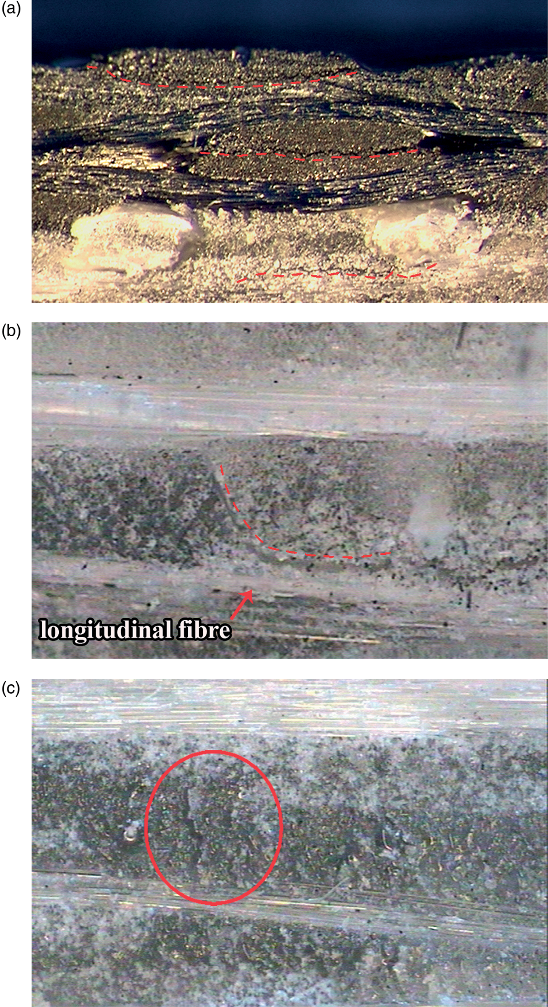
Another type of fatigue damage other than at CRP/GRP interface observed in CGRP hybrid system is a creation of cavities in transverse glass or carbon fiber bundles as shown in Figure 11. This may be considered for two different possibilities – one is by the hydrostatic stress and the other by random cracking. In general, a cavity can be formed in liquids or solids as a form of deformation as long as the hydrostatic stress exists and sufficiently strong under a certain stress condition [42,43]. However, the hydrostatic stress on the near-surface is weak (or theoretically zero on the surface) so that this possibility may be eliminated. In the absence of such hydrostatic stress, it may be then possible that multiple cracks were formed at random locations and sometimes joined together three-dimensionally around a part of transverse fiber bundle and, as a result, a localized separation occurred and broke away. More number of cavities were observed in GRP than CRP.
A cavity formed in transverse glass fiber bundles and longitudinal cracking. The arrows indicate edges of the cavity.
The fatigue microscopic damage patterns observed are summarized in Figure 12. The damage patterns in terms of cracking direction generated by fatigue loading may be expected to be similar to those by static loading because of similar stress distributions particularly at an early stage of fatigue damage. The difference, though, may be expected to be in damage initiation location at a later stage of fatigue damage. The reason for this is that the static damage process takes place rapidly prior to the final failure and thus is not much sensitive to small inherent material defects whereas the fatigue damage process is slow and its initiation locations are dependant on where inherent material defects are. Thus, the fatigue damage patterns are expected to be more unpredictable than the static damage patterns. It may be useful to compare fatigue (Figure 12) and static damage patterns [32] for differences. The following damage patterns were found in specimens damaged by fatigue loading only: (a) longitudinal cracking in either glass or carbon transverse fiber bundle, (b) transverse cracking in transverse glass fiber bundles, and (c) inter-glass fiber bundle delamination. Otherwise, the damage patters are similar to each other.
Schematic summary of various fatigue damage patterns observed in CGRP hybrid: (a)–(d) transverse cracking initiated from delamination (or meta-delamination); (e) inter-ply delamination; (f) longitudinal crack in transverse fiber bundle; (g) cavity in transverse carbon fiber bundle; (h) GRP/CRP interface delemination; (i) cavity in transverse carbon fiber bundle and longitudinal cracking; (j) transverse cracking between two cavities in transverse glass fiber bundles; (k, l) transverse cracking originated from interface; (m) transverse cracking through both transverse and longitudinal fiber bundles; and (n) longitudinal cracking in glass fiber bundle.
At a large scale, it was commonly observed that the inter-fiber bundle delamination occurs more in CRP sub-system than GRP sub-system as shown in Figure 13 for two different load ratios. More damage in a form of inter-fiber bundle delamination at R = 0.1 than at R = 0.25 is seen as expected. This macroscopic observation appears to support the Second Hypothesis.
Inter-fiber bundle delamination at a large scale on thickness area of test specimen with a hole diameter of 5 mm after the fatigue damage: (a) at R = 0.1; and (b) R = 0.25. CRP sub-systems display severe inter-fiber bundle delamination compared with GRP sub-systems, and more severe at R = 0.1 than at R = 0.25. (The inter-fiber bundle delamination appears as the darkest color and gaps in contrast with undamaged CRP plies.)
The two hypotheses coupled with the difference between static and fatigue loading in damage process seem to help understanding why the relative damage sensitivity (q) for the hybrid system is much better under static loading than under fatigue loading. Also, it should be noted that the First Hypothesis is partially associated with the stochastic process while the Second hypothesis is directly associated with deterministic damage mechanisms.
Conclusions
A theoretical framework is proposed as a guide to deal with the complexity involving uncertainties and a large number of variables in the hybrid composite systems. A relative damage sensitivity factor expression or criterion has been developed for the quantitative comparison between non-hybrid and hybrid composite systems as part of the theoretical framework. The relative damage factor expression is theoretically validated for any possible cases where various combinations are possible due to differences in strength reduction rate after fatigue damage between two different composite systems. The hybridization conducted is found to be beneficial for damage sensitivity under one of four different fatigue conditions although its effect is marginal while three other conditions are not in favor. New damage mechanisms of hybrid laminates due to the dissimilarity between GRP and CRP systems were hypothesized and tested to be valid with the evidence based on macroscopic and microscopic examinations.
Footnotes
Funding
The authors wish to express their gratitude to UPM for providing a research grant and to UITM for the support throughout the work. Also, one of authors (HAH) gratefully acknowledges the financial support for UNIPRS and UNRS from the University of Newcastle.