
Abstract
In this study, the effect of incorporating nano-sized fillers (noncovalently functionalized with ethoxylated alcohol chemical-vapor-deposition-grown SWCNTs) within an epoxy resin on the performance of filament wound glass fiber (GF)-based cylindrical composites (GFCCs) was investigated. For this purpose, SWCNTs were dispersed with the concentration of 0.05 and 0.1 weight percent (wt.%) within an epoxy resin using mechanical stirring and calendaring (3-roll-milling) techniques. The rheological behavior of the SWCNT incorporated epoxy mixture was characterized to determine the suitability of blends for the filament winding process. It was revealed that the viscosity value of the resin was not significantly affected by the addition of SWCNTs in given concentrations. Moreover, contact angle measurements were also performed on the SWCNT/epoxy blends dropped on the GF for the evaluation of the wettability behavior of the GF in the presence of the SWCNTs in relevant concentrations. Eventually, it was observed that the wettability behavior of GF was not reasonably affected by the presence of the SWCNTs. The double cantilever beam (DCB), flexural, and short beam shear (SBS) tests were performed on the reference and SWCNT-modified GFCC specimens to evaluate the effects of the SWCNT presence on the interlaminar fracture toughness and out-of-plane properties of GFCCs. The fractured surfaces after the DCB and SBS tests were analyzed under the scanning electron microscopy to reveal the toughening mechanisms and the filler morphologies. Consequently, although SWCNT incorporation was on the outermost layer of GFCCs, it was found that the interlaminar shear strength (ILSS) values and Mode I interlaminar fracture toughness values of the curved composite samples were improved up to 22 and 216%, respectively, due to the presence of the SWCNTs.
Keywords
Introduction
In recent applications, especially for transportation, aerospace, and gas, liquid, and chemical storage in the modern industry, high-performance materials have gaining interest. The fiber-reinforced polymeric composites (FRPC), which consist of a polymeric matrix and continuous fibers (GF, carbon fiber (CF), basalt fiber (BF), etc.), provide the desired light-weight and high-performance structures. Achieving performance targets and the further integration of structural systems have created the concept of multi-functional FRPCs, which are also called “multi-scale reinforced composites.” These composites exhibit enhanced performance, safety and versatility, and reduce product size, weight, cost, and power consumption. Thus, they have recently drawn the most attention among the researchers, who study composite materials.
Among the several production methods, the filament winding method is a widely used one for manufacturing high strength continuous fiber-reinforced thermoset composites in the form of the uni- and multi-directional lamina, pipes, tanks, etc. Cylindrical FW composite materials are traditionally used in high-pressure areas, chemical storage, and space, nuclear and defense sectors, and gas and/or oil tanks and transfers. 1 Continues and conventional fibers—such as carbon fiber (CF), glass fiber (GF), and aramid fiber (AF)—are mostly used to produce cylindrical composite. GF and CF reinforced cylindrical composites are other examples that have been widely used in long-term pressure vessel applications. 2 GFCCs have been widely used for pressure vessel applications due to their high strength, stiffness, and good fatigue resistance. For the pressure vessel and pipe applications, an optimum winding angle for the combined internal pressure and axial loading was reported as ±55°. 3
Based on the type of composite pressure vessels, they can be exposed to impact loads. FRPCs are not durable to the transverse impact loading, and under loading pressure, vessels can be exposed to fiber fracture, delamination, shear failure, and matrix crack. 4 Damage in FW tanks starts at the epoxy matrix and progresses by the formation of leakage path, delamination, and, finally, fiber breakage.5,6 In decades, inorganic fillers are often used to increase the stiffness of the polymer matrix materials. Nevertheless, the usage of high concentrations of commercial fillers is not appropriate for the process of filament winding due to the increment of the viscosity to the high levels. 7 Thereby, impregnation of nano-sized fillers at low concentrations may enhance the interlaminar shear strength, interlaminar fracture toughness, and load transferability of FW fiber-reinforced storage vessels.8,9
The mechanical performance of the multi-functional FRPCs highly depends on the production process and time, nano-sized filler type, the ratio of nano-sized filler to the matrix, etc., and interfacial interaction between the materials (fiber, matrix, and nano-sized filler). 10 For the development of a nano-sized filler incorporated FRPCs, the dispersion quality of the filler within the matrix material is a critical aspect. The physical methods and interfacial modifications with a chemical agent are important steps for enhancing the homogeneous dispersion of nano-sized fillers within the resin.10,11
Interlaminar shear strength (ILSS) is a matrix-dominated property, and the interlaminar shear properties of FRPCs are important for many applications due to a limiting characteristic design feature. In recent studies, it was revealed that the ILSS property of conventional fiber-reinforced composites (BF, GF and CF) can be improved by 7–50% due to the incorporation of CNTs within the polymer matrix.9,12–20 Matrix modification with nano-sized fillers is an effective way to improve the interlaminar shear properties of FRPCs. In the study of Qiu et al., GF-based FRPCs manufactured by vacuum-assisted resin transfer molding (VARTM), with 1 wt.% of MWCNT filled epoxy resin exhibited a 7.9% improvement in ILSS values. Fan et al. obtained a higher improvement on ILSS of GF/epoxy composites manufactured with injection followed by double vacuum-assisted resin transfer molding (IDVARTM) and 2 wt.% of MWCNT incorporation.14,16 Amino functionalized CNTs at 0.3 wt.% incorporation further enhanced ILSS improvement regardless of the production method of FRPCs.9,15,17 Besides the usage of bulk resin modification methods, the usage of fiber coatings with the nano-solvent suspension to manufacture multi-scale FRPCs also improved the ILSS values.21,22 Furthermore, besides CNTs, the other nano-sized fillers; such as graphene, silica, alumina, etc. and in their various forms, have been widely used to improve the ILSS of the multi-scale FRPCs, however, the improvements were not greater than those for the CNTs.12,23–30
Curved composite structures may be exposed to external forces, especially due to service conditions. Toughening the matrix with a nano-sized filler addition has a critical importance to improve the interlaminar shear behavior of the cylindrical FRPCs. In a study, ILSS of FW Naval Ordinance Laboratory-ring (NOL-ring) was improved by 28% due to 6 wt.% of MWCNT-NH2 incorporations. 19 In another study, a synergetic effect of core-shell rubber and a rigid nano-sized SiO2 incorporation on the mechanical properties of FW CF/epoxy NOL-ring was studied. In addition to other mechanical properties, ILSS was also improved due to the nano-sized filler. 28
Delamination is a damage type that occurs throughout the circumferential directions in cylindrical FRPCs. When the force is applied to the cylindrical FRPCs structures, curved regions of the composites are exposed to bending moment, which results in delamination in the curved regions. Therefore, the determination of interlaminar fracture toughness of curved composites is of great importance for their performance. There are several numerical and experimental studies in the literature for determining the delamination propagation of cylindrical FRPCs.31–37 In both experimental and numerical studies of Ghadirdokht, FW flat and curved laminated composites were tested under Mode-I load. While the curvature did not affect the initiation toughness, it increased the steady-state toughness and decreased the fiber-bridging length. Based on the numerical studies, it was revealed that delamination modeling in curved samples can be considered as the same as for flat samples. 31 In the study of Liu et al., curved carbon fiber reinforced polymeric composites showed significantly higher Mode-I fracture toughness values as compared to those for the strait one. 35
In some studies, nano-sized fillers were used to produce composite pressure vessels. Among those studies, the most common one has been the utilization of the nano-sized fillers incorporated within the matrix resin for the production of vessels.38,39 Moreover, nano-sized filler incorporated liners were also used. 40 Toughening of the polymeric matrix with nano-sized fillers is expected to enhance the interaction between commercial fiber and epoxy, and hence the delamination resistance of the composites. Consequently, the resistance of FRPCs to blast loading or hard object impact loading is expected to increase.
For this study, a toughened matrix with the SWCNT was used for the manufacturing of FW GFCCs. GF is a good candidate for filament wound cylindrical composites for the application of pressure vessels and piping systems due to its high strength and stiffness, good fatigue resistance, and providing a smooth internal interior, which ensures lower liquid loss than a typical piping system economically. 41 Also, the used nano-sized material (SWCNT) improves fracture toughness as well as other mechanical properties of epoxy resins even at minimum concentrations, considering the large surface area and high mechanical properties of SWCNTs.8,9 Since the filament winding ensures to manufacture of type III composite vessels for hydrogen gas storage, GFCCs were manufactured by the filament winding process with a ±55 winding angle. The effect of the usage of a modified epoxy resin system to produce GFCCs on the mechanical performance of the cylindrical composite structures was experimentally studied within this study.
Materials and methods
Materials
A continuous E-glass fiber (FWR06 1200 tex, supplied from Sisecam Elyaf Sanayii Inc., Turkey) as a reinforcement and single-walled carbon nanotubes (SWCNTs) (TUBALLTM Matrix 301, supplied from Pinhas Inc. of Turkey) as a nano-sized filler were used in the current study. SEM image of the as-received non-covalently functionalized SWCNT is shown in Figure 1. The outer diameters of the selected SWCNTs were measured based on the SEM images (Figure 1) and an image analyzer software (Image JTM). The average outer diameter was measured as about 2 nm. A thermoset epoxy resin (Araldite® MY740), curing agent (Aradur® HY918), and accelerator (DY062) were used as matrix materials with weight ratios of 100:85:1.3, respectively. SEM images of as-received non-covalently functionalized SWCNT.
Manufacturing of cylindrical composites
Mixing stages for the preparation of epoxy blends at 5 µm gap sized and variable mill speeds.

Impregnation of resin was carried out by roller impregnation, which enhances the winding process with minimum fiber damage and a minimum amount of excess resin. 42 The fiber direction of GFCCs was [±550]2. For creating an initial crack along the interlaminar region of DCB test specimens in the transverse directions, a non-adhesive release layer with a thickness of 19 µm was inserted between the 1st and 2nd laminates during the filament winding process. After the end of the winding process, the FW cylindrical composite product was cured at 800C for 2 hours, followed by a post-curing at 1200C for 2 hours within a controlled rotary oven. The produced GFCCs with an outer diameter of 275 mm and a thickness of 5 mm were removed from the mandrel and carried for sample preparation.
Abbreviation of the specimens, SWCNT contents,

Instrumentation and testing
Three-point bending tests were performed for the evaluation of the flexural properties and interlaminar shear strength (ILSS) of GFCCs. The flexural test and short beam shear (SBS) test specimens were sectioned from the produced reference GF/epoxy, GF/005SWCNT/epoxy, and GF/01SWCNT/epoxy specimens. A support span-to-depth ratio for all composites was selected as 32:1. Samples for three-point bending test for measuring flexural properties are 5 mm in thickness, and their length was set based on the span-to-depth ratio (32:1) in the accordance of ASTM D 790-03. The tested samples for SBS are 30 mm in length, and 10 mm in width in the accordance of ASTM D 2344, where mentioned as SBS for curved samples.
Three-point bending tests were accomplished by a 5 kN Shimadzu AGS-X tester for each specimen. Flexural strength and flexural modulus were calculated. Figure 2 illustrates the flexural and SBS test configurations of the curved samples. According to the relevant ASTM standards (ASTM D 790-03 and ASTM D 2344), flexural strength, flexural modulus, and ILSS were calculated based on the equations given below, respectively Images of (a) the flexural test and (b) the SBS test configurations with GF/xSWCNT/epoxy composites.


The Mode I interlaminar fracture toughness ( Schematically illustrations of (a) produced CFRPCs, (b) Transverse DCB test specimen.

At the first stage of the DCB loading, samples were initially loaded, and the crack was allowed to propagate 5 mm after the initial crack before the specimens were unloaded, and the
Scanning electron microscopy (SEM) images were taken for fractured surfaces after the DCB test of GFCCs to determine the failure modes and to evaluate the delamination and toughening mechanisms. The specimens were coated with a thin gold layer using a sputter-coating for 90 seconds and examined under a Quanta 250FEG SEM at various magnifications.
The rheological behavior of the neat and SWCNT incorporated epoxy suspensions was measured by an oscillatory rheometer (TA InstrumentsTM) with a 25 mm parallel plate geometry and a 0.5 mm sample gap. The rheological behavior of the neat and SWCNT (0.05 and 0.1 wt.%) incorporated suspensions at temperatures between 25 and 1200C was characterized while a constant shear rate (100 s−1) was applied for at least three repeats of all suspensions. 11
To produce FW cylindrical composites, complete wetting is a critical issue for obtaining the high performance of the composites. The viscosity of the epoxy resin increases with the addition of nano-sized particles. High viscosity complicates the wetting of the fibers. Thus, observation of the spread of the epoxy suspension on the GF with the pendant drop method offers an alternative observation for high-quality production of the composites during the filament winding process in addition to the viscosity measurements of the epoxy suspensions. The pendant drop is an experimental method for measuring the contact angle between the liquids on solid surfaces. The contact angle between the surface of the wetted solid and a line tangent to the curved surface of the drop at the point of three-phase contact is measured to get information about the interactions between the surfaces.43,44
Also, an optic tensiometer (Biolin Scientific Attension Theta) was used to measure the contact angle values according to the pendant drop method. The wettability behavior of fiber depending on the SWCNT incorporation within the epoxy was determined. Neat and SWCNT (0.1 wt.%) incorporated suspensions were dropped on GF by a micropipette with a 5 µm in volume, and the volumetric change in the drop was monitored for 200 seconds. The measurements were carried out at least three times for all suspensions.
Results and discussion
The viscosity of the neat and SWCNT (in various content) blended epoxy suspensions in the presence of hardener and accelerator as a function of shear rate at room temperature was studied in the previous paper. 11 At low shear rates, the viscosity value of SWCNT (0.05 and 0.1 wt.%) blended epoxy suspensions did not exceed 2.0 Pa.s, which is a suitable viscosity value during filament winding for wetting the continuous filaments at room temperature. 11
The viscosity of the neat and SWCNT blended epoxy suspensions, which was used in the production of GFCCs, as a function of temperature at 100 1/s shear rate is given in Figure 4. It was observed that the viscosity of the suspensions is not significantly affected by the incorporation of SWCNTs. As expected, the viscosity values were decreased by increasing temperature. The viscosity of the suspensions reached its lowest value at 800C, which is the curing temperature of the epoxy suspensions used within the study. Temperature dependency of the viscosity of neat and SWCNT blended suspensions at 100 1/s shear rate.
Figure 5 shows the spread of neat and 0.1 wt.% SWCNT incorporated epoxy suspensions on a single GF surface for 200 seconds with the pendant drop method of surface tension analysis equipment. Based on visual observations, the spread and the form of the suspensions were found to be almost the same. Hence, it can be concluded that the wettability of GF is not affected by the incorporation of SWCNTs with the epoxy resin, even at its highest concentration (0.1 wt.%) used in the present work. (a) Neat epoxy suspension, and (b) Suspension with 0.1 wt.% SWCNT drops on a single GF surface in 1st and 200th seconds at room temperature.
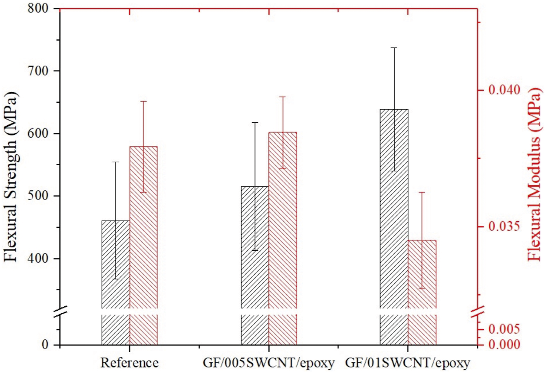
Figure 6 illustrates the stress vs strain curves of composites under flexural bending loading. Also, the slope of the curve in Figure 6 was increased by increasing SWCNT content. The calculated maximum flexural strength and modulus of GFCCs are given in Figure 7. While the maximum increase on the stress level (37%) was obtained for the specimens containing 0.1 wt.% SWCNTs, the maximum flexural modulus values were obtained for the specimens containing 0.05 wt.% SWCNTs. On the other hand, the flexural modulus values were decreased slightly for the specimens labeled as GF/01SWCNT/epoxy. Stress vs strain curves of GF/epoxy, GF/005SWCNT/epoxy, and GF/01SWCNT/epoxy cylindrical composites manufactured by filament winding. The average flexural strength and modulus values of GFCCs manufactured with filament winding.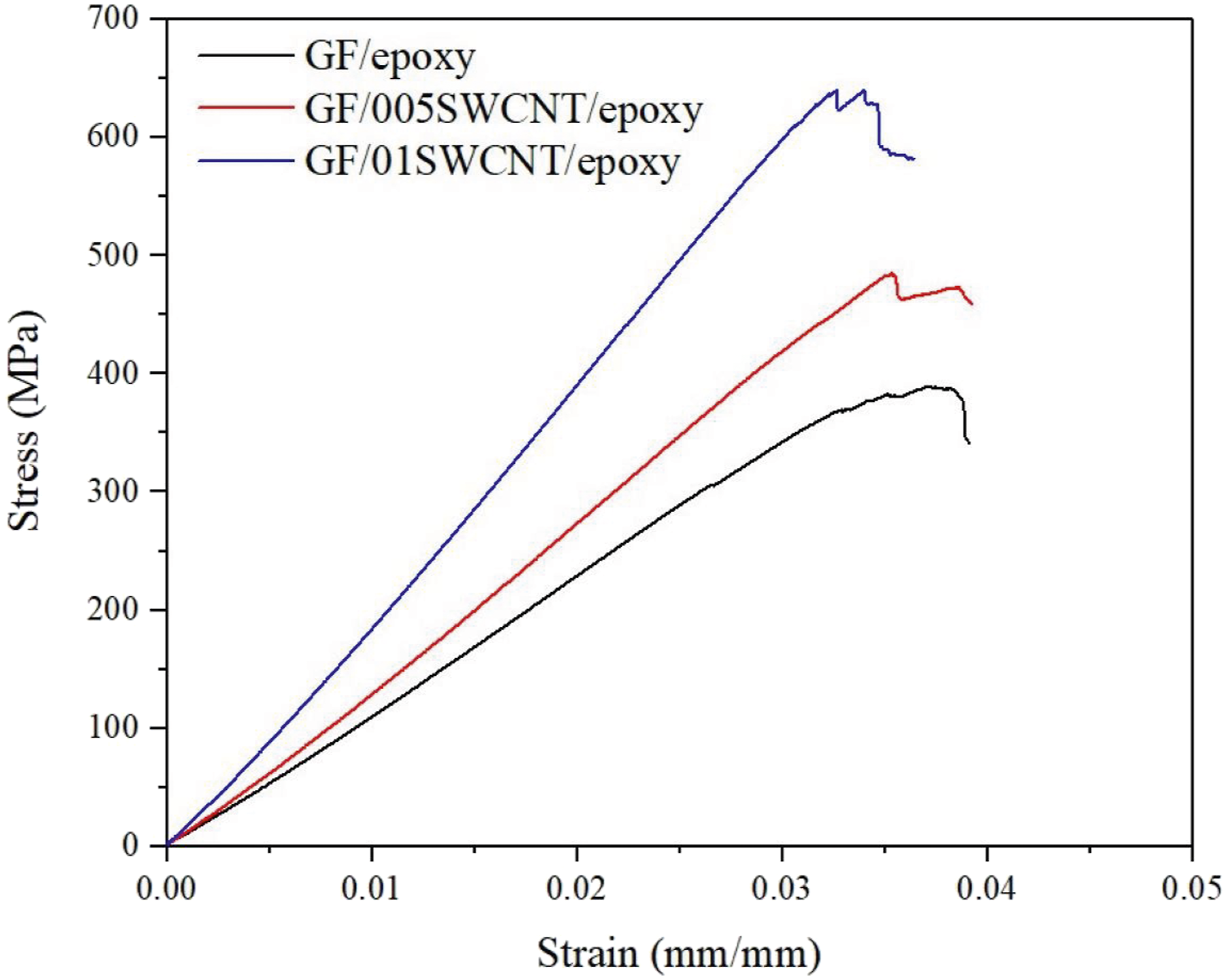
The matrix system in composites governs the out-of-plane properties of the composites. So, the out-of-plane properties of FRPCs are highly affected by nano-sized filler incorporated within the matrix. ILSS can be measured if the interlaminar shear failure is observed. Fan et al. reported that pure interlaminar shear failure is obtained in the case that the load is increased with a linear elastic behavior of composites and it is dropped dramatically due to interlayer delamination.
16
In the present study, ILSS values were measured based on the SBS tests and calculated with the equation (3), which also assign the ability of the fiber-based composites to resist delamination. Figure 8 illustrates the measured average ILSS values for GF/epoxy (reference), GF/005SWCNT/epoxy, and GF/01SWCNT/epoxy composites. The ILSS values were improved by about 22% with the incorporation of 0.05 wt.% of SWCNTs. However, ILSS was slightly decreased as the SWCNT content is increased to 0.1 wt.% of SWCNT (GF/01SWCNT/epoxy composites). ILSS of the curved CFRPCs.
As compared to the results reported within the literature, the improvement of the ILSS values obtained within the present study is greater than those observed by the other researchers.28,45 It should be noted that the studies reported in the literature were based on CF reinforced composites. To our knowledge, our work is the first reported in the literature focusing on the investigation of GFCCs with the SWCNT incorporation. Zhang et al. reported a 28% improvement on the ILSS of FW GFCCs with the incorporation of 6 wt.% NH2 functionalized MWCNT. 19 The reason for this higher efficiency reported in the literature may be related to the usage of a large amount of CNT. In this study, unlike the other studies reported in the literature, an increase of 22% for the samples with 0.05 wt.% of SWCNTs was obtained by incorporation of SWCNTs within the epoxy resin of the outermost layer of GFCCs.
Figure 9 illustrates the typical load-displacement curves of GF/epoxy, GF/005SWCNT/epoxy, and GF/01SWCNT/epoxy composites under Mode-I tensile loading. As seen on the graphs, the maximum load values were obtained for GF/005SWCNT/epoxy composite. In the load-displacement curves, the load increased linearly by increasing displacement in the initial region. The SWCNT incorporation increased the initial slope of GFCCs specimens. This is associated with the stiffening effect of the CNTs. In the 2nd stage, the crack propagates non-linearly with the fiber-bridging effects of the fibers that cause stick-slip behavior. In this stage during the crack propagation, the crack jump from one fiber to another and at the same time the unbroken fibers left behind the crack front. This mechanism results in the crack propagation that is not commonly observed for GF-based composites. Typical load-displacement curves of GFCCs with/without SWCNTs under Mode-I tensile loading.
Stick-slip behavior was found to be more dominant for GF/005SWCNT/epoxy composite. The fiber-bridging mechanism based on the stick-slip behavior is visible as shown in Figure 10 for GF/005SWCNT/epoxy composite. The crack started at the middle of the sample, then it tended to move the outer layer of the sample. Finally, the crack continued to progress in the middle of the sample. The crack jumping resulted in a lower level of fiber-bridging.
34
Fiber-bridging mechanism seen in GF/005SWCNT/epoxy specimens during Mode-I tensile loading.
Figure 11 illustrates the R-curves of the GF-based curved DCB samples. As seen in R-curves, the increasing behavior of the fracture toughness was varied in the slope, which is decreased by increasing SWNCT concentration. R-curves appear with the initiation toughness and increased with the SWCNT containing. Then it follows by the fiber-bridging mechanism, which is occurred with the crack jumping between the layers of DCB samples with a constant slope. After the fiber-bridging zone of the R-curves, the fracture toughness reached the steady-state values. The initiation and propagation toughness values were calculated and summarized in Table 3. While the initiation toughness values were increased to a maximum with the incorporation of 0.05 wt.% SWCNT, the maximum improvement was obtained with the incorporation of 0.1 wt.% SWCNT for propagation toughness values. According to the literature review, the Mode-I fracture toughness results from this study are higher than the studies reported in the literature.12,13,17,27,29,30,46–54 Furthermore, there is no study reported in the literature about enhancing the Mode I interlaminar fracture toughness values of filament wound GFCCs with SWCNT toughened epoxy. The remarkable conclusion is that the Mode I fracture toughness of GFCCs was considerably increased, because of the usage of SWCNT containing epoxy incorporated only at the outermost layer of GFCCs during the filament winding process. GIc versus delamination length of GF/epoxy, GF/005SWCNT/epoxy, and GF/01SWCNT/epoxy composites. Average initiation and propagation fracture toughness 

The fractured surfaces of samples after the DCB test were examined with SEM at various magnifications as illustrated in Figure 12. The micrographs were captured from the middle of delaminated layers and away from the initial crack of composites. As seen in Figure 12(a), smooth surfaces are evidence of easy crack propagation, no extensive fiber-bridging, and less deformation during crack propagation of the reference sample. The roughness of the fractured surfaces was increased with the addition of SWCNTs concentration (Figure 12(b) and (c)). Rough surfaces indicate that SWCNT enhanced the fracture toughness with the deformation and bridging mechanisms. This may be also associated with the enhancement of the wettability of the fibers by the epoxy resin with the existence of SWCNTs. Furthermore, the epoxy layer observed on the fiber surfaces of the images of the fractured surfaces of GF/005/SWCNT, and GF/01SWCNT/epoxy indicates the enhancement of the interfacial adhesion between the fiber and epoxy with the incorporation of SWCNT within the epoxy matrix. The crack propagation through the resin was affected by the toughening mechanism at the epoxy resin region as shown in Figure 12(d). As a conclusion of the SEM images, both GF and SWCNT contributed to the improvement of the interlaminar Mode I fracture toughness of GFCCs containing SWCNT. Fractured surface SEM images of DCB specimens for (a) GF/epoxy, (b) GF/005SWCNT/epoxy, (c) GF/01SWCNT/epoxy at 1000x magnification, and (d) GF/01SWCNT/epoxy at 2500x magnification.
Conclusion
This study investigates the enhancement of mechanical properties of filament wound (FW) glass fiber (GF)-based cylindrical composites (GFCCs) due to incorporation of the SWCNTs within the epoxy matrix. SWCNTs in 0.05 and 0.1 wt.% concentrations were dispersed within the epoxy resin by a mechanical stirrer and calendaring system (three-roll-mill). The rheological properties at increasing temperature and contact angle behavior of the prepared blend were accomplished. Based on the results, it was found that; • the viscosity of the epoxy resin was not significantly affected by the incorporation of SWCNTs in concentrations used within the study. • the spread and wetting behavior of the neat and SWCNT incorporated epoxy blends were the same on the GF carried to filament winding process.
Since the viscosity of blends was suitable for the filament winding process, the prepared blends were directly impregnated onto continuous GF during filament winding process. Three-point bending tests (flexural and ILSS properties) and DCB tests were carried out to investigate the effect of the SWCNTs on the mechanical behavior of the composites. Based on the mechanical test results, it was found that; • while the flexural strength was increased by increasing SWCNT content, ILSS was improved by up to 22% with the incorporation of 0.05 wt.% SWCNT. • although SWCNT incorporation was on the outer most layer of GFCCs, Mode I interlaminar fracture toughness of the curved composite samples was improved up to 216%.
As the future work, the end-notched flexure (ENF) test can be performed to investigate the Mode II fracture toughness for the evaluation of interlaminar fracture toughness under in-plane shear deformation load to provide further information about the interlaminar properties.
Footnotes
Acknowledgement
The authors acknowledge the valuable financial support of TÜBİTAK. The tuball SWCNTs from OCSiAl used in this study were supplied from PİNHAS A.Ş. The SEM images were taken by IYTE Center for Materials Research (CMR).
Declaration of conflicting interests
The author(s) declared no potential conflicts of interest with respect to the research, authorship, and/or publication of this article.
Funding
The author(s) disclosed receipt of the following financial support for the research, authorship, and/or publication of this article: This study was supported by TÜBİTAK (project ID 215M182).