
Abstract
The final mechanical properties of composite laminates are highly dependent on their curing cycles in the autoclave. During this cycle, the temperature, pressure, vacuum, and treatment time will influence the quality of manufactured parts. The void content is considered the most harmful defects in carbon/epoxy laminates since they weaken the matrix-dominated mechanical properties such as interlaminar shear and compressive strengths. In the present work, differential scanning calorimetry is used to characterize the influence of time/temperature on the behavior of the epoxy resin. Then, a series of [0/90/−45/+45]s laminates composites are autoclave-cured under various applied pressures to evaluate their impact on microstructure and mechanical properties. The interlaminar shear modulus, interlaminar shear strength, laminate compressive modulus, and laminate compressive strength at room and operating engine temperature were measured. The correlation between microstructure and mechanical properties was also studied. The mechanical properties of manufactured carbon/epoxy laminates are found to be dependent on pressure and microstructure. These results are explored to establish an optimal autoclave pressure route that would minimize porosity without counterbalancing mechanical properties.
Keywords
Introduction
Carbon fiber reinforced polymers (CFRP) are increasingly used in aerospace applications because of their higher thermal and mechanical properties compared to conventional composites. They are also superior to their metallic counterpart regarding corrosion and fatigue resistance. 1 Widespread application of lightweight materials with high mechanical properties as aircraft materials yield improvement in fuel efficiency, increased payload, and flight range, all of which directly reduce an aircraft operating cost. 2 By improving and optimizing the mechanical properties of CFRP, the time between maintenance can also be lengthened to reduce repair costs. These benefits have allowed the use of carbon fiber-reinforced polymer in modern passenger aircraft such as Boeing 787 and Airbus A350 (up to 50% of their weight in CFRP). 3
Laminate composites are manufactured using several methods. The most frequently used are the autoclave process and the out-of-autoclave process. 4 Autoclave processing yield structures with less than 1% of porosity and high mechanical integrity.5,6 However, the autoclave-curing parameters need to be chosen carefully to achieve good results, among which are curing temperature and time, pressure, and bag vacuum level. For instance, the curing temperature and time affect the polymerization/crosslinking reactions of the epoxy resin. The reaction mechanism and curing process determine the final composite characteristics and its mechanical properties. 7 In epoxy/amine-based resin, polymerization/crosslinking reactions occur at specific temperatures and result in the opening of the epoxy ring, resulting in the formation of ethers and alcohol groups and the conversion of primary amines to secondary and tertiary amines. 8 The pressure applied on the laminate surface inside the autoclave allows the CFRP to conform to the mold shape and to be compacted to the desired fraction of fiber volume, thus reducing the voids likely to form during the curing cycle. The vacuum is used to remove any entrapped air and volatiles during the curing cycle.
In earlier studies, the curing pressure was used to create different levels of voids in laminates9–13 in an attempt to find out a relation between mechanical properties and voids4,10–12,14 or pressure.12,14 These studies confirmed that a decrease of curing pressure increases porosity, yielding in turn reduced mechanical properties. Composites produced by Liu et al. 9 yielded decreasing void content from 3.2% to 0.6% when applied pressure was increased from zero to 0.6 MPa, while ILSS increased by 18%. Costa et al. 10 reported a similar trend for ILSS of carbon epoxy laminates, where a 34% decrease is observed when void content increases from 0.55% to 5.60%. Di Landro et al. 15 noticed a decline of ILSS up to 25% in composite with the highest porosity (7%), compared to composite laminates with no void content.
While the influence of pressure on manufactured parts is more documented, the current literature available is poor on the impacts of temperature.16–19 This is compounded by the fact that the void formation mechanisms within composite laminates during autoclave curing are not fully understood. While some studies point to dissolved moisture in the resin as a possible cause of void formation, 20 where autoclave pressure could force moisture to remain in solution thus preventing the formation and expansion of voids, 21 other studies point to entrapped air and volatiles as the primary source of voids. 22
Engine aircraft nacelles currently incorporate many significant composite components, where carbon/epoxy prepregs account for almost half of the total volume of the nacelle structure. Among the possible composites for engine aircraft nacelles where a continuous service temperature of 120°C is to be expected, the woven Hexply 8552S/AS4 is the object of this study. This work aims to evaluate the impact of input autoclave conditions on the final microstructure of laminate composites and optimize the resulting mechanical properties by adjusting pressure. This will be achieved first by evaluating through Differential Scanning Calorimeter (DSC) the behavior of epoxy resin during time-temperature treatment. The goal is to predict the time/temperature treatment cycle enabling a total polymerization/crosslinking and, to some extent, help achieve energy saving during autoclave processing. Once established, this cycle is used to prepare in an autoclave under various pressures laminate composites, which will be assessed in terms of density, thickness, and voids content. Mechanical properties, namely laminate compressive strength (LCS), laminate compressive modulus (LCM), interlaminar shear modulus (ILSM), and interlaminar shear strength (ILSS), will be established at room temperature and the expected continuous service temperature of 120°C. Correlations between microstructure and mechanical properties such as LCM, ILSM, LCS, and ILSS will be discussed. The relationship between LCM and ILSM, and between LCS and ILSS will also be established.
Experimental procedure
Materials
The material used in this study is a woven carbon fiber/epoxy prepreg (Hexply 8552S/AS4/280H5) manufactured by Hexcel France. It is a high-performance epoxy matrix for use in primary aerospace structures. Hexply 8552S is an amine cured, toughened epoxy resin (37% resin content) reinforced by woven carbon AS4 PAN-based carbon fibers (3000 filament counts tows) with 280 g/m2 areal fiber weight. Hexply 8552S uses a 180°C curing epoxy matrix. 23 The prepreg was stored in hermetically sealed packing at −18°C. DSC analysis and autoclave manufacturing were performed within the 12 months shelf life limit (from date of manufacture). Samples under its packaging were placed at room temperature for 1 day before their uses; their out-life was 17–18 days.
Thermal analysis
A differential scanning calorimeter (DSC Q20, TA Instruments) was used to simulate the heat flow change during the autoclave curing cycle and evaluate the behavior of Hexply AS4/8552S. Before each DSC run, a neat prepreg sample (10 mg) was encapsulated in a standard aluminum sample pan. The encapsulated sample was then put in the DSC cell, and all experiments were carried out under nitrogen environment. For the dynamic measurements, the DSC cell was heated at a constant rate of 3°C/min over a temperature range of 35 to 320°C. The resulting sample was the second run specimen, and the test was performed using the same conditions. Combined analysis between isothermal and non-isothermal was performed at a heating rate of 3°C/min to 180°C, after which the sample is held at that temperature for 170 min. The resulting sample was analyzed using a 3°C/min dynamic scan until the specimen was fully cured to determine the residual enthalpy.
Fabrication and curing
CFRP 8 layers samples, having a dimension of 20 × 20 cm, were laid up by hand to achieve quasi-isotropic [0/90/−45/+45]s stacking sequence. The samples were then autoclave-cured, using one of the cycles shown in Figure 1 that were derived from DSC results and manufacturer recommended cycles (MRC). The cycle of thermal curing proposed by Ng and Tomblin 24 was adopted; the heating rate for all testing was set at 3°C/min to reach the dwell temperature of 180°C during 90 min (dwell time was determined based on DSC results), while a 3°C/min ramp down was used. Various pressures (0.1/0.3/0.5 and 0.7 MPa) were chosen to study the effect of curing pressure variation while the vacuum was fixed at −0.02 MPa. Sample curing was performed in an autoclave manufactured by Taian Techtop Industries (China), using vacuum bags (Online Supplemental Figure S1).

Curing cycles used to fabricate 8552S/AS4 composites.
Density and void content
The density of the laminate was measured following ASTM D792-13, using water as the immersion liquid. 25 The void content was measured by the digestion method, following the ASTM D3171-15, 26 using heated concentrated sulfuric acid to dissolve the resin.
Optical microscopy
The void shape, location, and sizes were examined using optical microscopy, Nikon Eclipse LV100ND (Japan), equipped with a DS-Ri2 camera. The specimens for porosity analysis were polished using a polishing machine (Unipol-820) with 400, 600, 1000, and 2000 grit size silicon carbide abrasive paper.
Mechanical properties
The combined loading compression (CLC) and short beam shear (SBS) tests were conducted on a Universal Testing System (MTS Criterion model 45, MTS Systems Corporation (USA)) according to ASTM D6641/6641M–16 27 and NF EN 2563, 28 respectively. The dimensions of CLC and SBS samples were 140 × 13 × e and 20 × 10 × e, respectively (e is the thickness). As this is a quasi-isotropic laminate, the mechanical properties are equal in all directions within the plane of the laminate. Therefore, the tests were carried out in only one direction. Testing at service temperature was achieved by the mean of an environmental chamber (Thermcraft Lab-Tem LBO, Thermcraft incorporated, USA) allowing the sample’s temperature to reach the consign value without influence on the load cell. SBS tests were performed at room temperature and 120°C, whereas CLC tests were conducted at 120°C. At elevated temperature, a delay of 10 min was imposed before testing. Five to seven specimens were tested for each test and temperature condition.
Results and discussion
DSC
DSC was used to characterize the influence of time/temperature on the behavior of the epoxy resin. For this purpose, heat flow is recorded using either dynamic or a combination of dynamic and isotherm measurements depending on the curing conditions. The dynamic DSC curves are shown in Figure 2. Two consecutive runs are performed to evaluate any changes caused by the first heating cycle. As seen by the shift in Figure 2(a) of the heat flow signal to higher values, an exothermic reaction attributed to the polymerization process begins from ∼155°C and reaches a maximum at ∼190°C. A second peak at ∼236°C, found in the tail end of the first, is attributed to the crosslinking reaction. This phenomenon is observed only in the first run, as the second run does not show any significant heat flow exchange. This difference is explained by the complete curing of the epoxy during the first run. Figure 2(b) represents changes in the heat flow of the specimen as a function of time during the first run. The area under the exothermal peak is calculated by drawing a linear baseline between onset and end. This value corresponds to the heat of curing. As the obtained value of 211.61 J/g is for prepreg containing 37 wt.% of resin, the curing heat thus obtained amount to 571.92 J/g.
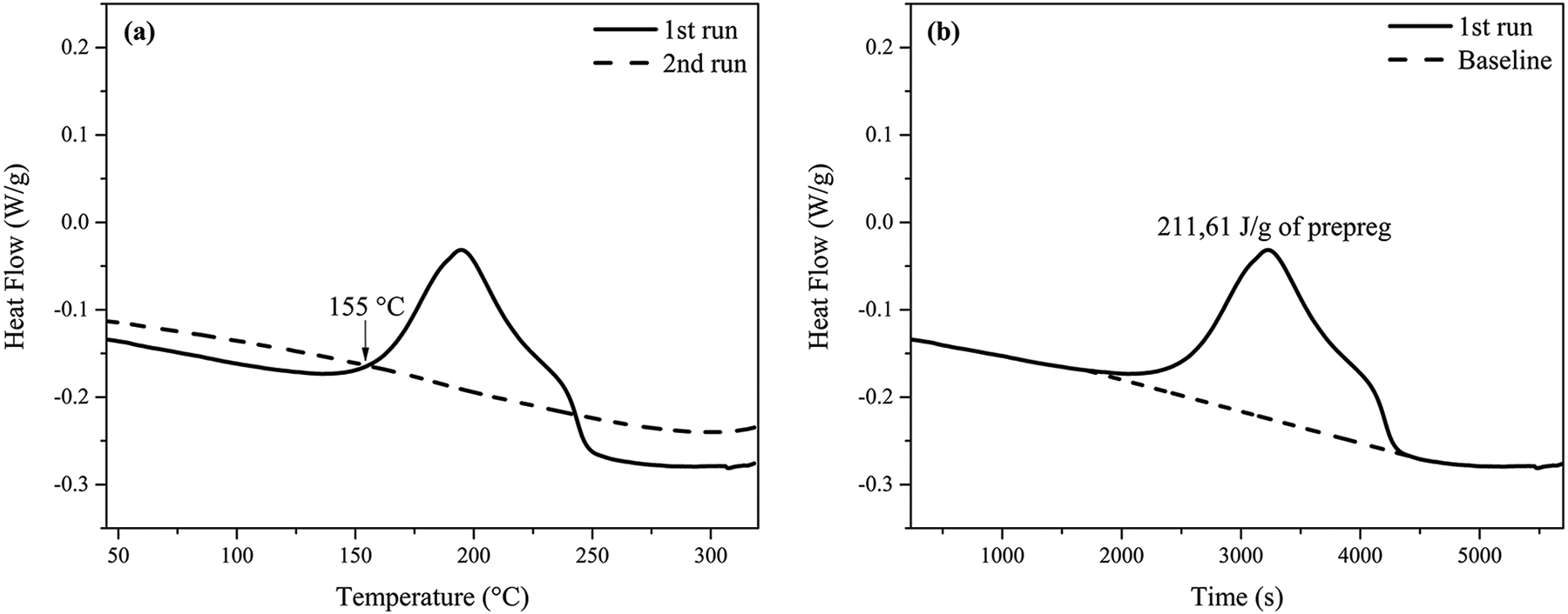
Dynamic DSC analysis: Heat flow vs temperature (a) and time (b).
To achieve maximum curing during the autoclave cycle while minimizing the required time, a combined analysis between dynamic and isothermal was performed at a heating rate of 3°C/min to 180°C, after which the sample is held at that temperature for 170 min. The goal of the test is to evaluate through DSC the degree of curing and the rate of reaction during the curing cycle as well as the minimum time duration necessary to achieve the optimum cure (Figure 3). The DSC profile simulating the autoclave cycle (Figure 3(a)) shows a heat reaction (ΔH) equal to 522.89 J/g of resin (193.47 J/g of prepreg). This value is comparable to the total heat (ΔHt) obtained from our previous measurement by dynamic test (571.92 J/g). The DSC curve becomes horizontal near the end, meaning that curing is close to complete. The final degree of curing is equal to 0.914. This value is confirmed by cooling down the sample and performing a second heating run in dynamic mode. The resulting DSC curve (Online Supplemental Figure S2) yields a value of residual enthalpy equal to 44.62 J/g of resin (16.51 J/g of prepreg), implying a residual conversion of 0.078. However, it has been shown After a degree of cure of 0.9, the mechanical properties remain practically unchanged. 19
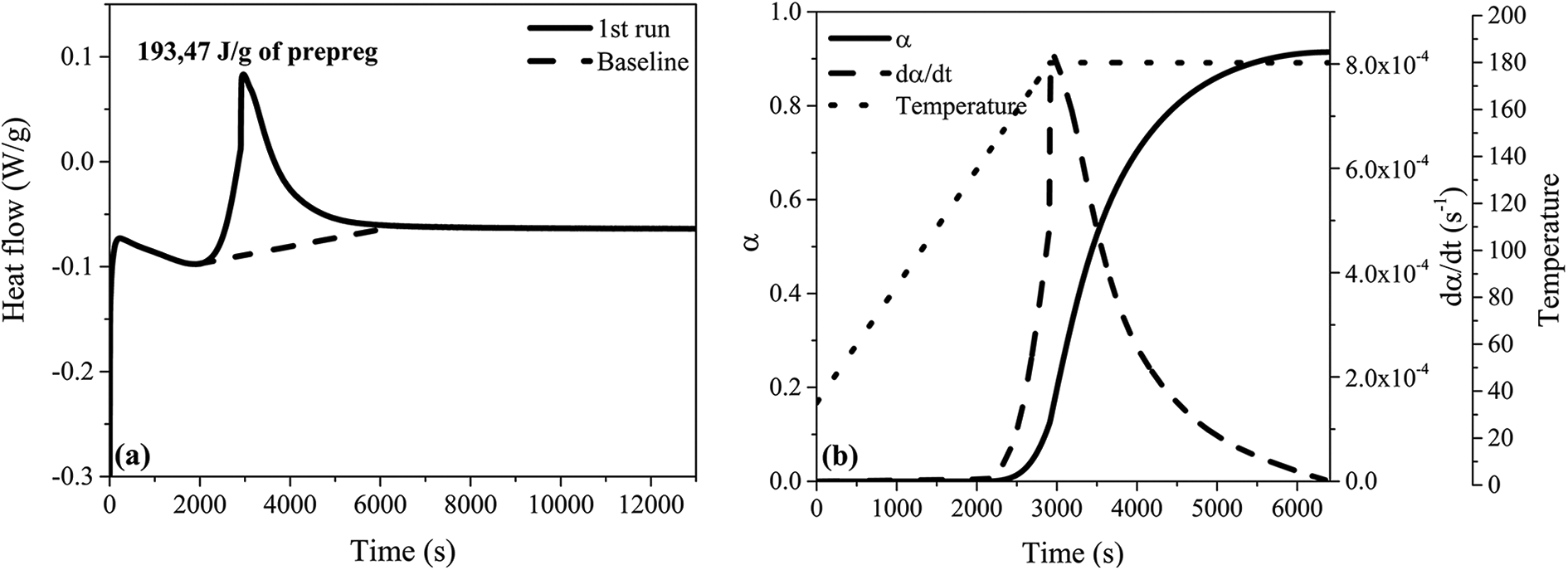
(a) DSC curve simulating the autoclave curing cycle (heating to 180°C at 3°C/min and hold) and (b) temperature, degree of cure, and reaction rate as a function of time in the autoclave curing cycle.
To predict the reaction progress over time, the degree of conversion at each instant t is calculated by integrating the area under the exothermic curve as follows:

The reaction rate is then determined by the differential of the curve α = f(t), which is assumed proportional to the heat generation and expressed as:

Variation of temperature, degree of curing, and reaction rate as a function of time are represented in Figure 3(b), where it can be observed clearly that the reaction rate is low at the beginning (∼155°C). Once temperature approaches 180°C, a sharp increase in reaction rate is observed, reaching its maximum value of 8.14E-4 s−1. After ∼16 min at isothermal temperature, the reaction rate decreased to 2.92E-4 s−1 while the degree of cure reached ∼0.68. The maximum degree of conversion (0.914) is attained after about 1 h at isothermal temperature. It can be concluded from these results that composites laminates must be maintained at 180°C for 1 hour during the autoclave curing cycle.
To gain a better understanding of the behavior of the resin, the development of cure during autoclave curing cycle simulate by DSC is investigated using the model proposed by Cole et al. (equation 3), 29 and used and tested by Garstka et al. 30 :

where α is the degree of cure, t is the time (s), m and n are reactions orders, C is the diffusion constant,
In our case, Figure 4 showed the model predictions which indicates that the Cole et al. model is a good model fit for the epoxy resin studied in this work (R2 = 0.973). The corresponding values of the parameters are summarized in Table 1.

Reaction rate vs. degree of curing plot with a model provided by Cole et al.
Curing kinetics parameters for 8552S/AS4 resin.

Effect of curing pressure on microstructure
The manufactured laminate composites were carefully controlled in terms of carbon fiber and epoxy resin. A visual inspection of vacuum bags showed no loss of fiber during the autoclave curing process. A loss of the resin was however observed depending on the applied pressure; as we will see, this is proven by optical microscopy images and acid digestion. FTIR analysis confirmed results obtained by simulating the thermal cycling through DSC. Disappearance after curing of the bands associated with the epoxy ring and the primary amine is explained by the total reaction of these functional groups with each other (Online Supplemental Figure S3).
The influence of cure pressure on microstructure has been presented in Figure 5, whereas Figure 6 illustrates optical microscopy images of each composite. Figure 5(a) presents the average thickness and density of composites vs. curing pressures. As clearly illustrated, the thickness decreases with increasing curing pressure while density increased. According to Figure 6, there is a reduction in the thickness of each layer, resulting from the increase in cure pressure. These results provided good support for the theoretical hypothesis that sample thickness and density depend greatly on applied pressure. As a result, the cure pressure ensures good adhesion between different prepreg layers of a composite laminate. Thickness variation was found to present a logarithmic fitting curve (R2 = 0.999) as a function of applied pressure, whereas the density shows a third polynomial curve fitting (R2 = 1). At 0.1 MPa, the laminate composites have an average thickness and density of 2.10 mm and 1556 kg/m3, respectively. When curing pressure is increased to 0.3 MPa, thickness reduces to 2 mm while density reaches 1572.76 kg/m3. Increasing pressure further to 0.5 MPa yield another 2.75% decrease in thickness and a 2.57% increase in density. Applying a 0.7 MPa pressure yield composites with a thickness of 1.916 mm and a density of 1632.85 kg/m3.

Influence of pressure on (a) density, thickness, (b) fiber volume fraction, resin volume fraction, and void content.

Optical microscope images through the thickness of composite laminates taken at 50× magnification: (a) at 0.1 MPa, (b) at 0.3 MPa, (c) at 0.5 MPa, and (d) at 0.7 MPa.
The influence of cure pressure on the fiber volume fraction, resin volume fraction, and void content has been presented in Figure 5(b). As the imposition of more pressure leads to remove a large amount of resin (Figure 6), a decrease in resin volume fraction and an increase in fiber volume fraction were observed (Figure 5(b)). By comparing the various optical microscope images, we notice that the frequency and size of resin-rich areas found in composites decrease with increasing pressure; they are usually found between layers, which constitute the laminated composite. Figure 5(b) also showed that the void content decreased as the cure pressure increased from 0.1 MPa to 0.7 MPa, behavior reported by multiple authors.9,13,31 For a curing pressure of 0.1 MPa, laminates exhibit a high void volume content. The voids are very large (Figure 6(a)), having an irregular shape (meso-void). 32 Many reports identified low pressure as a highly detrimental parameter for laminate composites, leading to high void content and lower mechanical properties.12,31,33 Li et al. 34 found that when the applied pressure is low, an important number of large voids mostly at ply interfaces are created, of which the number and size reduce significantly when the cure pressure is increased. Increasing the curing pressure of the autoclave to 0.3 MPa yield a 25% decrease in void content to 4.19% when compared to samples prepared at 0.1 MPa. At 0.5 MPa, the void content is significantly reduced to attain a value of 0.05%, representing a 99.1% reduction from the level measured at 0.1 MPa.
At high curing pressure (0.7 MPa), a negative void volume percentage was calculated (−0.17%). This is explained by the fact that calculation of void content assumes a constant density for filler and matrix during the autoclave curing process, 26 both of which vary slightly. Based on optical microscope images (Figure 6(a) to (c)), the voids generally are located between the layers. Researchers who have studied the effect of curing cycle pressure on void formation observed that voids occurred mostly at the ply interface and concluded that the voids are much larger, flattened, and elongated at low curing pressure while exhibiting a spherical shape at higher pressure.9,12 When applying high pressure (Figure 6(d)), adjacent prepreg layers would become bonded together at a faster rate, and thus inhibit any entrapped voids between layers. 35 By the action of pressure, voids are encouraged to disperse and dissolve within the resin consequently causing a lower void content and high fiber volume fraction. 36
Effect of curing pressure on mechanical properties
Autoclave pressure significantly affects the thickness and density of laminate composites, as well as voids content and fiber volume fraction. Samples with minimal porosity, high density, minimal thickness, and high fiber volume fraction should thus produce the best mechanical behavior. This hypothesis was tested by measuring the ILSM, ILSS, LCM, and LCS (Figure 7). The ILSM and LCM strongly depend on the applied pressure (Figure 7(a)). When curing pressure is increased from 0.1 MPa to 0.5 MPa, the corresponding ILSM at room temperature and 120°C increases of 41.01% and 49.37%, respectively. When pressure is increased to 0.7 MPa, a slight decrease in the ILSM can be observed. Equally, an increase in LCM from 4360.731 MPa to 5206.301 MPa is observed when the cure pressure increases (Figure 7(b)), representing an improvement of 19.39%. The increase in LCM is particularly significant when cure pressure increase from 0.5 MPa to 0.6 MPa with a relative variation of 10.53% between these pressures.
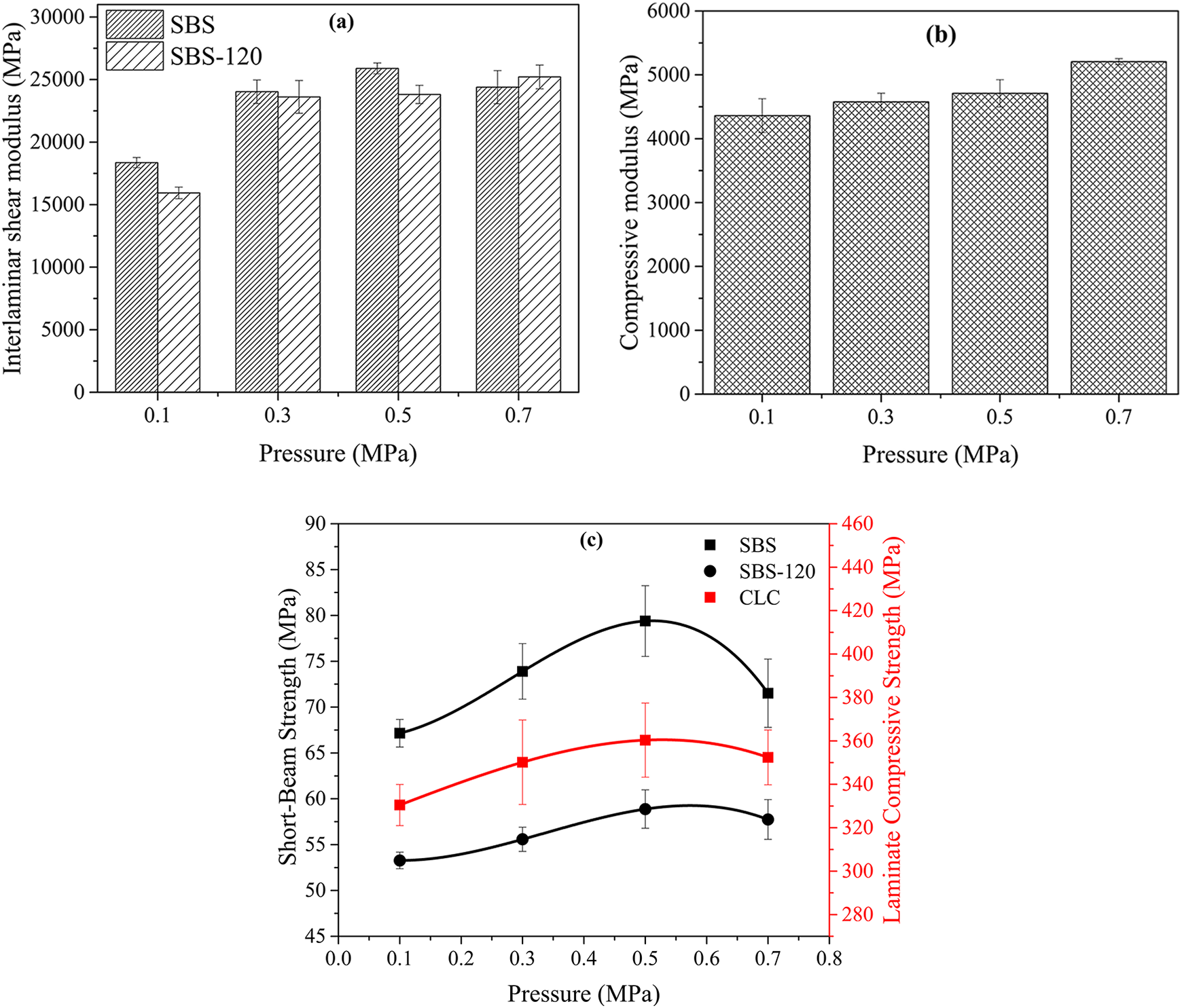
Mechanical properties as a function of pressure at room and 120°C: (a) ILSM (b) LCM and, (c) ILSS and LCS.
The LCS and ILSS of the composite laminates are shown in Figure 7(c). For a curing pressure of 0.1 MPa, laminates exhibit low mechanical properties in terms of LCS and ILSS. Many reports identified low pressure as a highly detrimental parameter for laminate composites, leading to high void content and lower mechanical properties.12,31 The fracture mechanism of composites cured at low pressure is mostly delamination, causing the cracking of the matrix. The presence of interfacial porosity and in-between fibers may be a contributing factor. 37 Increasing pressure of the autoclave to 0.3 MPa yield a 5.96% increase in LCS to 350.17 MPa when compared to samples prepared at 0.1 MPa. The ILSS and ILSS-120 also show improvement by 10.04%, and 4.34%, respectively. At 0.5 MPa, the LCS, ILSS, and ILSS-120 all show improvement to reach their maximum values at 360.34 MPa, 79.39 MPa, and 58.88 MPa respectively.
The mechanical properties of laminated composite materials are affected by their microstructure. To be able to correctly interpret the mechanical behavior, it is necessary to study the relationship microstructure-mechanical properties (Figure 8). Figure 8(a) and (b) depict the mechanical properties as a function of density. They argued that improved density should increase mechanical properties. This is generally due to the elimination of the porosity between the layers, and the thickness reduction under the influence of pressure.

Correlation between physical and mechanical properties: ILSM and LCM vs. density (a), ILSS and LCS vs. density (b), ILSM and LCM vs. fiber volume fraction (c), ILSS and LCS vs. fiber volume fraction (d), ILSM and LCM vs. void content (e), and ILSS and LCS vs. void content (f).
As the mechanical properties of carbon fiber are higher than those of the matrix, the mechanical properties of CFRP composite laminates would be mainly determined by their fiber volume fraction. This is enshrined clearly in Figure 8(c) and (d), which represent the correlation between fiber volume fraction, and LCM, ILSM, LCS, and ILSS. As already outlined, a higher fiber volume fraction implies a small matrix volume fraction and, as a consequence, a reduction in the amount of matrix surrounding the carbon fibers and decreased structural integrity of the composite laminate. 35
Correlations between void content and mechanical properties are presented in Figure 8(e) and (f). They show that the mechanical properties are inversely proportional to the void content, especially between 0.05% and 5.56%. At low porosity, other structural defects such as fiber damage or the prepregs sheet sliding because of high pressure could explain the decrease in composite resistance. The low matrix volume fraction probably destroys the mechanical properties of composite laminates. Santos et al. 38 highlighted a decline of 27% in ILSS caused by the presence of macroporosity that induced crack initiation and connection of different delamination plies, causing the speeding up of crack propagation and jump of the interlaminar layer.
Our results are in good agreement with the theoretical hypothesis excepted at high pressure. Similar behavior was reported by others.9–11,39 Hernández et al. 39 and Zhu et al. 11 concluded that neither the resin nor the interface strength can explain the ILSS decrease of composites with low voids content, and is probably caused by the difference in void morphology. Chang et al. 13 stated that when the applied pressure is too high, the resin will flow too fast and will induce local defects such as poor adhesion, fat rat, and distorted fibers.
The determination of the relationship between the various mechanical properties of 8552S/AS4 composite laminates will allow us to predict its behavior without conducting the particular test. As the SBS test method is simpler than the CLC method, the LCM is plotted against ILSM (Figure 9(a)), and LCS is plotted as a function of ILSS (Figure 9(b)). LCM was found to present an exponential fitting curve (R2 = 0.989) as a function of ILSM, whereas the LCS increased proportionally with the ILSS; this result being similar to that previously reported by Vo et al. 40

Correlation between LCM and ILSM (a), and LCS as a function of ILSS (b).
Conclusions
The influence of applied pressure during the autoclave curing process on the quality of laminate composites was studied. The curing pressure was fixed at either 0.1 MPa, 0.3 MPa, 0.5 MPa, and 0.7 MPa, while the temperature was constant at 180°C and vacuum set to −0.02 MPa. At low curing pressures, the laminate composites presented a higher void content than what is measured at high pressure. The presence of voids, density, and fiber volume fraction was found to impact significantly the mechanical properties. Increases in LCS, ILSS, and ILSS-120 of 9.04%, 18.22%, and 10.52%, respectively, are observed when curing pressure is raised from 0.1 MPa to 0.5 MPa. A comparison of ILSS at room and service temperatures shows the sensitivity of mechanical properties to temperature variation.
Plots of mechanical properties as a function of porosity and pressure enable the selection of an optimal curing pressure route, which minimizes porosity while maximizing the mechanical properties of composite laminates of woven carbon/epoxy AS4/8552S.
Supplemental material
Supplemental Material, sj-pdf-1-ppc-10.1177_09673911211028413 - Cure kinetics and autoclave-pressure dependence on physical and mechanical properties of woven carbon/epoxy 8552S/AS4 composite laminates
Supplemental Material, sj-pdf-1-ppc-10.1177_09673911211028413 for Cure kinetics and autoclave-pressure dependence on physical and mechanical properties of woven carbon/epoxy 8552S/AS4 composite laminates by Abd Baghad, Khalil El Mabrouk, Sébastien Vaudreuil and Khalid Nouneh in Polymers and Polymer Composites
Footnotes
Acknowledgment
The authors acknowledge the financial support received, respectively, from the EuroMed University of Fes (Morocco), the Hassan II Academy of Science and Technology (Morocco), and Safran Nacelles (France).
Declaration of conflicting interests
The author(s) declared no potential conflicts of interest with respect to the research, authorship, and/or publication of this article.
Funding
The author(s) disclosed receipt of the following financial support for the research, authorship, and/or publication of this article: This work was supported by the EuroMed University of Fes (Morocco), the Hassan II Academy of Science and Technology (Morocco), and Safran Nacelles (France).
Supplemental material
Supplemental material for this article is available online.
References
Supplementary Material
Please find the following supplemental material available below.
For Open Access articles published under a Creative Commons License, all supplemental material carries the same license as the article it is associated with.
For non-Open Access articles published, all supplemental material carries a non-exclusive license, and permission requests for re-use of supplemental material or any part of supplemental material shall be sent directly to the copyright owner as specified in the copyright notice associated with the article.