
Abstract
Liquid crystal polymers (LCPs) derive favorable mechanical, chemical, and electrical behavior from long-range molecular ordering. The microstructure gives rise to anisotropic bulk properties that are problematic for industrial applications, and thus the ability to model the polymer directionality is essential to the design of isotropic material manufacturing processes. This investigation proposes a modeling methodology to simulate the 3D director field in full-scale film extrusion geometries. Wide-angle x-ray scattering (WAXS) is used to validate the predicted orientation for a standard coat-hanger die, and is compared with macroscopic mechanical, thermal, and dielectric testing of LCP film to illustrate the morphological dependence of the polymer properties. The highly anisotropic orientation state resulting from cast film extrusion is both predicted by the model and confirmed experimentally, and this preferred orientation is shown to correlate with observed anisotropy in the bulk properties. Additionally, a practical implementation of the modeling tool is presented to simulate directionality in two alternative die geometries designed to improve bulk isotropy, and it is demonstrated that the model is capable of simulating the resulting order for large, irregular domains typical of industrial processing.
Introduction
Liquid crystal polymers (LCPs) comprise a class of high-performance plastics that can be cast film extruded and injection molded. Typical LCP attributes include high mechanical strength, chemical inertness, inherent flame retardancy, low permeability, high temperature resistance, and frequency-stable dielectric behavior.1-4 Accordingly, LCPs are ideal candidates for high strength-to-weight ratio components, semiconductor packaging, and high-frequency electronics.5-10 The characteristic LCP behavior is a result of the unique polymer microstructure, which in contrast to conventional amorphous and semi-crystalline plastics, consists of highly oriented domains in both the melt and solid phases. 11 The long-range molecular ordering present in LCPs drives the formation of a hierarchal structure, and ultimately gives rise to anisotropic bulk properties.12,13 Such directionally-dependent performance can be problematic for industrial applications requiring isotropic behavior and the high capital investment for manufacturing equipment discourages iterative design to achieve the desired polymer performance. Thus, an understanding of the fundamental LCP structure-property-processing relationships is essential to drive the proactive design of isotropic material manufacturing methods.
Typical LCP melt-processing techniques include injection molding and cast film extrusion. During both processes the polymer experiences high shear and temperature gradients that drive the formation of a hierarchal skin-core microstructure, and ultimately lead to the directional macroscopic material behavior.14-18 Indeed, Dreher et al. and Rendon et al. observed that orientation of the nematic structure along the flow, or mold/machine, direction (MD) leads to higher elastic modulus; the same orientation was seen by Donald and Windle to produce a lower, or negative, coefficient of thermal expansion along MD, as compared to the transverse direction (TD).11,19,20 Similar anisotropy has also been observed between MD and TD in both the low dielectric constant and low dielectric loss exhibited by LCPs. 21 Understanding the intricacies of the melt flow during processing, and the subsequent effect the flow has on the polymer texture, is thus necessary to control the material morphology (and ultimately the bulk properties) resulting from manufacturing.
Due to the inherent tendency of the LCP molecules to form oriented domains, extensive work has been prompted into understanding and predicting the evolution of preferred orientation. The typical means through which the polymer directionality, or molecular alignment, is expressed is through the orientation state of the director field. A director, designated as
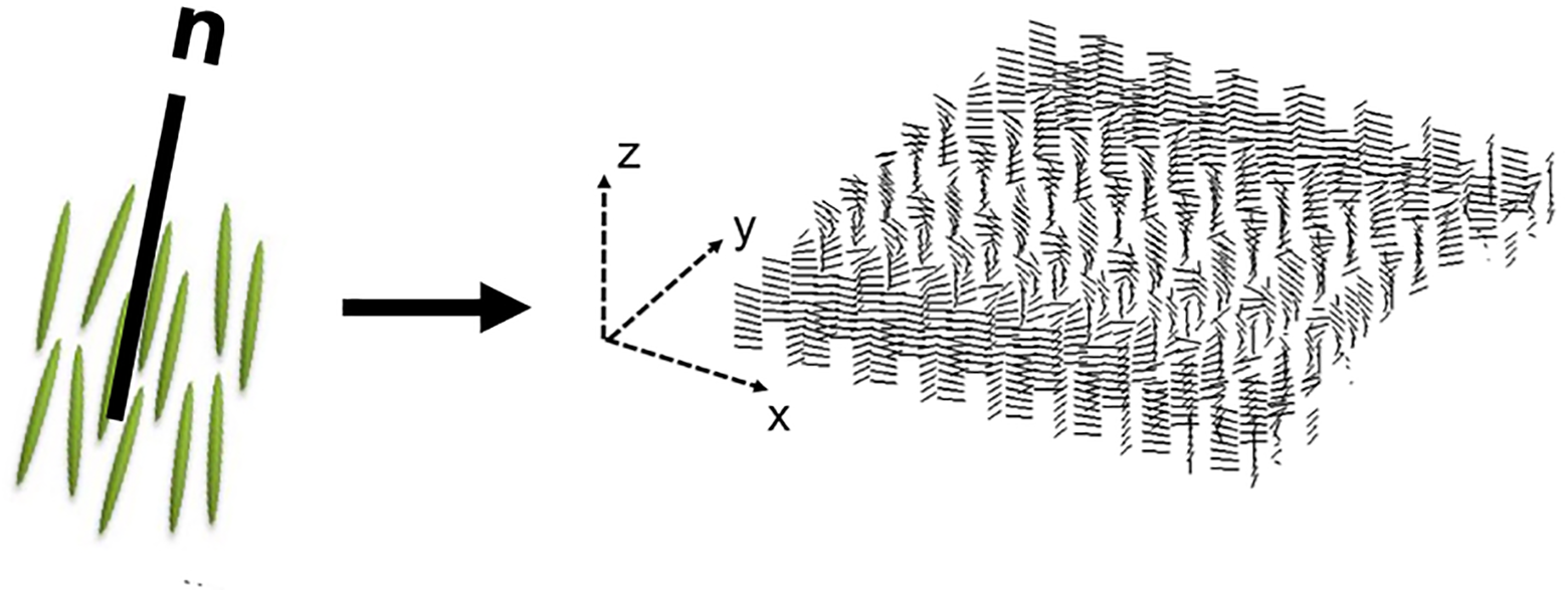
A director (left), representing a small volume of LCP molecules, and the director field (right).
Various phenomenological models have been implemented to describe the director dynamics. In the quiescent state, Frank developed the elastic interactions associated with misalignment of adjacent directors.23-26 Rheological effects were then incorporated by Ericksen and Leslie; this framework has since been used to model director behavior under shear stresses, such as those present during melt-processing.27-31 More recently, Fang et al. demonstrated an implementation of Larson-Doi polydomain theory to simulate LCP directionality through various processing geometries using the injection molding simulation package, Moldflow.32-35
The variety of phenomena captured in the aforementioned models have served to validate the governing theories for director dynamics, however, have been restricted to structured grids, often with simplifications to the dimensionality of the flow. For practical LCP processing applications, there is a need to extend the modeling methods to large, unstructured grids, that can accurately capture both the scale and complexity of a 3D polymer flow through realistic LCP manufacturing set-ups, e.g. a coat-hanger extrusion die, shown in Figure 2. One candidate modeling methodology to bridge this gap between previous simulation efforts and industrial needs is based on the work of Goldbeck-Wood et al. 31 This hybrid approach, described in detail below, calls for simulation of the 3D LCP melt flow using conventional numerical methods, followed by post-processing calculations of the director field dynamics using the initial rheological modeling as an input. The result is a robust tool to predict polymer orientation, under various flow conditions, that benefits from the unstructured meshing capabilities and computational power of modern computational fluid dynamics (CFD) to accurately and efficiently model full-scale manufacturing geometries.
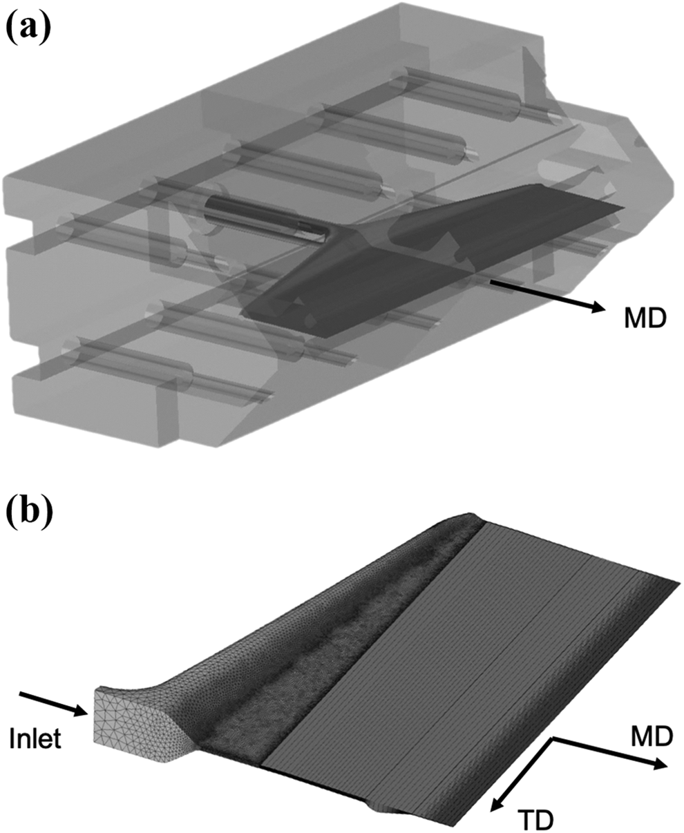
(a) A coat-hanger extrusion die flow domain, and (b) the mesh for the half-domain split down the die centerline.
This investigation demonstrates a practical implementation of the aforementioned hybrid modeling methodology to simulate LCP directionality during cast film extrusion. Previously validated for injection molding of LCP plaque specimens, this work serves to establish the robustness of the modeling tool across various melt-processing methods. 36 Simulation of two commercial LCP resins flowing through a coat-hanger die geometry was performed, and the degree of order, that is, how anisotropic the polymer morphology is, was quantified using an anisotropy factor. Experimental verification was conducted via wide-angle x-ray scattering (WAXS) on film samples. In addition, mechanical, thermal, and dielectric testing of the LCP film samples was performed to highlight the dependence of macroscopic polymer performance on the microstructure, providing further justification for the directionality simulation as a means to improve manufacturing processes. Two alternative extrusion dies were also considered in the model to determine the viability of using die geometry to alter preferred orientation. The full suite of simulations, scattering measurements, and material testing provide holistic insight into the structure-property-processing dynamics at play in extruded LCP films.
Modeling methodology
The directionality modeling performed in this investigation is carried out in two steps: first the 3D LCP melt flow is simulated using conventional numerical methods, and second, post-processing calculations are used to predict the director field orientation state using the initial rheological modeling as an input. This technique makes the assumption of one-way coupling between the polymer flow and directionality, that is, the flow affects the director orientations, however, the inverse is not true, for increased computational speed and simplicity in implementing and validating the model.37,38 It should also be noted that the same mesh is used for both the CFD and the directionality calculations, thus the mesh size must be optimized to ensure computational efficiency, but also capture the changes in texture throughout the polymer domain.
After completion of the initial flow analysis, the director field calculations are performed with a user-defined Matlab script, taking the velocity field, the velocity gradient field, and the mesh from the CFD simulation as inputs. Per Leslie-Ericksen theory, the unsteady and convective components of the change in director orientation are equal to the sum of the rheological and distortional effects:

where
The relative contributions of the viscous rheological and elastic distortional effects can be characterized by the non-dimensional Ericksen number:

where
The convective contribution from Equation 1,

where δx is the distance between the current node and its ith neighbor; the total convective contribution at each mesh point is summed over all neighboring nodes. To determine the final orientation state of the director field, Equation 3 is numerically integrated with respect to time using a second-order Runge-Kutta scheme that is carried out in a two-step process, following the procedure outlined by Bay. 39
Simulation details
CFD
The cast film extrusion rheological simulations were performed using ANSYS Fluent. The flow is assumed to be laminar, as justified by the Reynolds number, shown below in Equation 5, and the resulting 3D velocity and velocity gradient fields are provided as inputs to Equation 3 in the directionality modeling to calculate the 3D director field. The LCP melt is assumed to behave as a temperature-dependent (Arrhenius) power-law fluid, with the viscosity, μ, given by:

where K is the consistency index,

where ρ is the density, D is the characteristic length-scale of the flow, and
The initial cast film extrusion simulations considered the flow domain of a standard coat-hanger die, shown previously in Figure 2, with a die lip gap of 100 μm. The lone die inlet was used to apply a mass flowrate,

where ρ is the polymer density, v is the film speed, W is the film width and t is the film thickness. A single pressure outlet was prescribed at the die lip and no-slip was assumed at the walls. Temperature boundary conditions were prescribed in accordance with thermocouple readings from the actual die used to manufacture the experimental validation film samples. The mesh, consisted of a mixture of unstructured hexahedral, pyramidal, and tetrahedral elements totaling 895,000, with an average skewness of 0.18 and a maximum skewness of 0.93 (below the recommended maximum of 0.95).
Two alternative die geometries were also considered in the modeling tool to determine the viability of using a static die geometry to alter preferred orientation during processing. The first design, hereafter the spiral die, is shown in Figure 3(a), and implements a series of static corkscrew geometries (or spirals) in the die cavity to reorient the flow during processing and increase the polymer isotropy. The second die concept, hereafter the crossflow die, is shown in Figure 3(b), and consists of overlapping channels, offset by ±45° with respect to the die lip; the channels merge just prior to the lip to produce a biaxial orientation state across the film thickness. The spiral die mesh consisted of 11,000,000 elements due to the intricate nature of the spiral geometries, with an average skewness of 0.22 and a maximum skewness of 0.94. The crossflow die mesh had 168,000 elements with an average skewness of 0.29 and a maximum skewness of 0.5. Both geometries demonstrate the simulation of LCP directionality through unprecedented full-scale, irregular 3D geometries.

(a) The spiral die design, and (b) the crossflow die concept.
Directionality modeling
The directionality simulation was carried out through a user-defined script in Matlab. Using the same mesh as the CFD simulation, a random crystal orientation was initially defined for each mesh point in the flow domain and then the effects of shear and fluid convection were applied per Equation 3. While the flow velocity, vorticity, and strain rate were provided from the rheological modeling, the tumbling parameter had to be defined manually. Based on initial validation of the simulation tool with WAXS for LCP injection molding, a value of 1.01 was determined to best predict the measured orientation, and as such, the same value for λ was used in this investigation. 36
Experimental
Sample preparation
The cast extruded film samples were prepared with a 30-mm single-screw extruder paired with the steel coat-hanger die shown in Figure 2, that had a die lip width of 25 cm and the die lip gap set to 100 μm. Two commercial thermotropic neat LCP resins were considered, designated Resin A and Resin B in this investigation. Resin A is an aromatic polyester produced from 4-hydrobenzoic acid and 6-hydroxynaphthalene-2-carboxylic acid; commercially, the neat resin is considered extrusion grade due to its high melt strength which gives superior processability. Resin B is an aromatic polyester produced from 4-hydrobenzoic acid, 4-(4-hydroxyphenyl) phenol, and isophthalic acid. Despite the improved ease of processing of Resin A, both neat LCP resins were considered in this investigation to probe the effects of differences in viscosity and chemical structure on the resulting film orientation. Due to the differences in main-chain chemistry, the macroscopic properties are only correlated to orientation state within a single resin; the variation in performance between resins is not included in this investigation. Resins A and B have melt temperatures of 280°C and 320°C, respectively. Accordingly, Resin A was processed with a barrel temperature of 310°C and a die lip temperature of 295°C, and Resin B was processed with a barrel temperature of 340°C and a die lip temperature of 315°C. For both resins, the processing line was run at a film speed, that is, the rate at which the film was collected on the windup roll, of 8 m/min. The nominal film thickness for both resins was 100 μm.
Wide-angle X-ray scattering (WAXS)
Both the direction and degree of preferred orientation in the film samples were measured via wide-angle x-ray scattering (WAXS), a common technique used extensively to characterize LCP morphologies.40-42 Holding a fixed angle between the x-ray source and the detector, azimuthal intensity scans were performed in transmission mode by rotating the LCP specimens around the axis normal to their thin direction and measuring the thickness-averaged scattering as a function of angle, β, in the MD-TD flow plane. Due to the ordering of the non-polar rod-like LCP-molecules, typical scattering is manifested as symmetric intensity peaks perpendicular to the direction of average molecular orientation. 11 A schematic overview of an azimuthal intensity scan in transmission mode, and the characteristic scattering for LCPs, is shown in Figure 4.

Azimuthal intensity scan of a sample with preferred orientation along MD (0°), and the resulting scattering pattern perpendicular to the direction of preferred orientation (±90°).
To quantify the degree of order from the scattering intensity data, an anisotropy factor (AF) was used:

where β is the molecular angle with respect to the flow direction, and 〈…〉 denotes the average over all molecules.
16
The value of AF is bound such that a perfectly isotropic orientation state gives a value of 0 and a perfectly aligned case produces a value of 1, thus making it an ideal metric for comparing the bulk anisotropy between samples. Following the methodology provided by Cinader and Burghardt, the anisotropy factor was extracted from the scattering intensity data beginning with the unit vector representation of a point on a polar azimuthal intensity scan,

in which 〈…〉 is the weighted azimuthal intensity distribution of

It should be noted that the anisotropy factor can also be calculated from Equation 7 for the simulation results, where β is the director angle projected into the MD-TD flow plane. Thus, the thickness-averaged degree of order can be compared between the model and experiments as a means of validation.
The 1D WAXS orientation measurements were performed in transmission mode on a Panalytical Empyrean diffractometer (Worcestershire, UK). The analysis was conducted with a Cu Kα x-ray generator at 45 kV and 40 mA using a Cu focusing mirror and X’Celerator optics as the source and detector, respectively. The azimuthal scans were performed with a fixed angle between source and detector, 2θ, of approximately 19.6°, with MD oriented along 0° in the β-plane for all specimens. In preparation for WAXS testing, specimens were punched along the film centerline with a steel die to create (27.1 mm) 2 square specimens.
Mechanical testing
Mechanical testing of the LCP film specimens was performed to determine the tensile modulus. Tensile specimens were prepared and tested per the guidance of ASTM D638. 43 The tests were performed in both the MD and TD sample directions on an Instron 3366 universal testing machine (Norwood, MA) with a 2 kN load cell at an extension rate of 25.4 mm/min. Rectangular specimens of constant cross-section were cut using a 12.7-mm wide JDC precision cutter. A gage length of 25.4 mm length was used for all film tests, so the specimens were cut to at least 76.2 mm in length to prevent slipping in the grips.
Thermal testing
Thermal, or thermomechanical, testing of the LCP samples was performed to determine the coefficient of thermal expansion (CTE). The film sample CTE values were measured with respect to MD and TD on a TA Instruments Q400 TMA (New Castle, DE). Rectangular specimens were cut measuring 10 mm × 3 mm, with the long axis corresponding to the direction of testing (either MD or TD). The specimens were clamped at both ends along the length in the Q400 TMA and a constant downward force of 0.5 N was applied to the bottom clamp. The dynamic specimen length was measured as the stage was heated from 20°C to 165°C at 5°C/min. The CTE, α, was calculated per:

where ▵L is the change in specimen length, ▵T is the change in temperature, and Lo is the original specimen length.
Dielectric testing
The dielectric permittivity was measured with respect to MD and TD for the LCP film samples. Given in its complex form, the permittivity, ∊, is expressed as:

where

where Vc is the volume of the resonant cavity, Vs is the volume of the specimen, fc is the center frequency of the empty cavity, and fs is the center frequency with the specimen in the cavity.
A rectangular waveguide with iris-coupled end plates operating in transverse electric (TE10) mode was used for the resonant cavity, in accordance with ASTM D2520. 45 The waveguide was powered by an Agilent Technologies 8722ES (Santa Clara, CA) vector network analyzer (VNA) and operated at an empty cavity resonant frequency of 8.9 GHz. The LCP specimens were prepared using the same steel punch as for the WAXS measurements, and, along with the known cross-sectional area, the thickness was measured for each to calculate the specimen volumes.
Results and discussion
Initial coat-hanger die directionality modeling
The director fields for both Resin A and Resin B were simulated using the Matlab script, and the anisotropy factor for the final orientation state was calculated for each. Although the directionality was simulated for the entire flow domain during the cast film extrusion process, the director field results presented below are restricted to a 27.1-mm wide region of the die lip, along the flow domain centerline, most representative of the final film orientation state leaving the die. The predicted results for this subdomain provide a direct comparison to the experimental samples measured via WAXS. For both resins, the director field probability distribution, that is, the fraction of directors at a given angle in the MD-TD flow plane, is shown in Figure 5. It should be noted that due to the non-polar nature of the directors (
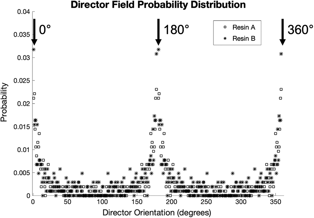
Simulated director field probability distributions for the coat-hanger die.
It can be seen in Figure 5 that both resins exhibit a single mode of orientation aligned with MD from peaks at 0°/180°/360°, with higher peaks in Resin B corresponding to a greater degree of alignment in this direction. Despite the larger MD mode, Resin B also shows a greater probability of directors aligned in off-angle directions, making the bulk orientation state more isotropic, albeit marginally. This variation in isotropy is evident in the calculated bulk anisotropy factors of 0.85 and 0.77 for Resin A and Resin B, respectively. The high degree of anisotropy is not surprising for the standard coat-hanger die geometry under consideration. In the die land, just prior to the lip, the gap in the die cavity drops from 1.1 mm to 100 µm to reduce the polymer to its final thickness; this decrease in gap height results in an increase in the flow velocity and wall shear rates, the latter of which are on the order of 1000 s−1 at the lip. Coupled with the predominantly 1D flow along MD, the flow-aligning directors are driven to a uniaxial orientation state along the film direction.
WAXS analysis
The thickness-averaged 1D scattering intensity as a function of angle in the MD-TD flow plane is shown for the 100-µm films in Figure 6. Both resins exhibit a pair of symmetric scattering peaks at ±90°; recalling the characteristic scattering of the LCP domains perpendicular to the direction of alignment, these peaks correspond to uniaxial orientation along MD, in accordance with the directionality modeling. It can be seen that Resin B has higher peaks, as in the simulated results, however, the WAXS scattering peaks are sharper, signifying a more anisotropic orientation state than Resin A, in contrast to the directionality modeling. Nevertheless, the primary mode of orientation observed in both resins is predicted by the modeling tool. The calculated experimental anisotropy factors were accordingly 0.81 and 0.89 for Resin A and Resin B, respectively, both of comparable value to the simulated results. Again, the highly anisotropic orientation along MD is typical of cast extruded LCP film, owing to the thin material geometry, high shear gradients, and one-dimensional flow at the die lip.
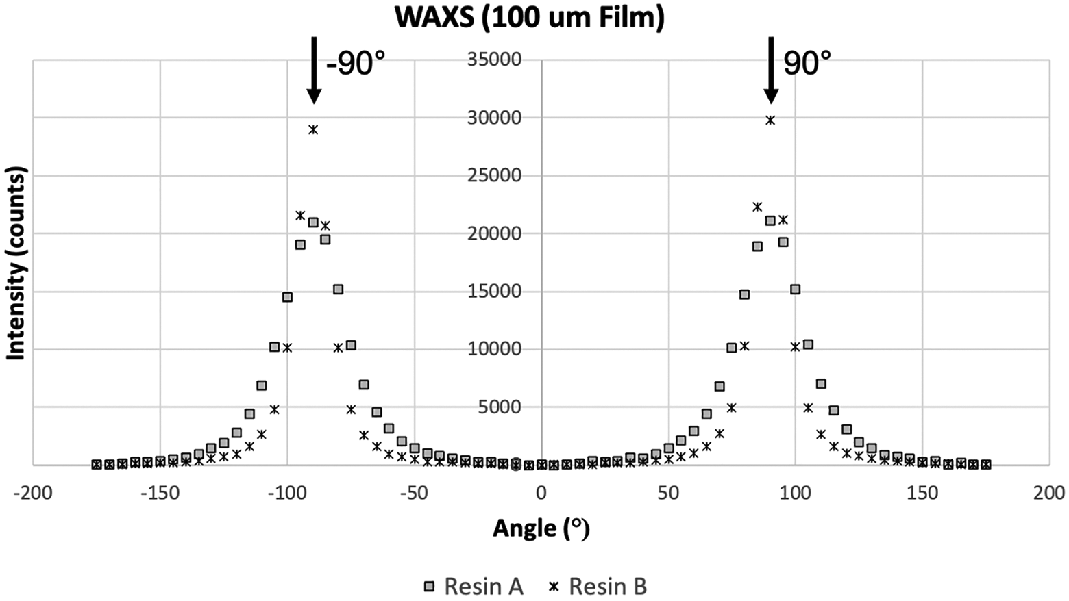
WAXS scattering of the 100-µm film with peaks at ±90°, corresponding to preferred orientation along MD (0°).
Mechanical, thermal, and dielectric material testing
The results of the mechanical testing are shown in Figure 7(a), with the ratio of the tensile modulus in MD to the modulus in TD given by R on the plot; a higher ratio corresponds to a higher degree of mechanical anisotropy. It can be seen in that the tensile modulus of both resins along MD is indeed much higher than that in TD, as expected, corresponding to the preferred orientation along the flow direction in both films. The modulus of Resin A is seen to be slightly higher than Resin B, however, the TD modulus is also marginally higher, resulting in a lower ratio. This is in accordance with the lower anisotropy factor calculated from the scattering data. Despite these minor variations between the two resins, both ultimately show a similar degree of anisotropy between MD and TD. The tensile modulus results confirm the strong underlying influence of the LCP microstructure on the observed mechanical behavior.

(a) Tensile modulus, (b) CTE, and (c) Dk for the 100-µm film.
The CTE results from the thermal testing of Resin A and Resin B are shown in Figure 7(b). The ratio between the MD and TD values is not given due to the presence of negative measured CTE values that would result in negative ratios; nevertheless, the difference between the MD and TD performance shown in the plots illustrate the relative degrees of anisotropy. A similar spread between the MD and TD values is seen for the two resins. Perpendicular to the direction of preferred orientation, the LCP molecules are free to undergo segmental motion and expand, resulting in a large CTE in TD, while parallel to this orientation, the CTE value is either small and positive, or negative, as the chain-extended linear alignment of the LCP molecules into crystalline domains prevents further extension upon heating. With respect to the negative expansion, or contraction, upon heating, such behavior has been observed in the work of Donald and Windle, and Green et al. and is attributed to segmental motion and rotations of the LCP chains with increased thermal energy that ultimately dominate over bond length extensions and angle fluctuations, resulting in a net decrease in chain length.11,46 As with the mechanical testing, the degree of anisotropy in the CTE behavior of both resins is heavily influenced by the polymer morphology.
The dielectric constant, Dk, for both resins is shown in Figure 7(c). Again, the ratios between MD and TD are annotated on the Dk plots to illustrate the degree of anisotropy. It can be seen that a similar ratio exists between the MD and TD values for both resins, with a slightly higher ratio for Resin B, in accordance with the higher calculated anisotropy factor. Despite the similar ratios, the absolute values differ, with lower overall Dk for Resin B. The difference in observed dielectric behavior may be attributed to differences in the resin chain chemistries; unlike tensile modulus and CTE, which are both functions of the bulk polymer deformation, Dk is derived from molecular and mesoscopic motion in the material. While the crystalline domain structure in both Resin A and Resin B serves to restrict chain mobility, the respective polymer chemistries may allow for differing degrees of segmental motion that would affect Dk. 44 Regardless, the dielectric behavior once again illustrates the dependence of bulk performance on the material morphology.
Alternative die geometry simulations
It is clear from the material testing that the macroscopic performance is heavily influenced by the polymer microstructure, thus demonstrating the need to improve morphological isotropy during melt-processing. Despite the success of post-processing techniques, such as biaxial stretching, and in some limited cases, dynamic die geometries (e.g. counter-rotating die), to improve the bulk property balance, these approaches add additional cost, time, and complexity to the LCP manufacturing process. 2 In an effort to determine a simpler, economic solution, the modeling tool was implemented to predict the directionality resulting from two alternative dies, specifically designed to improve isotropy through static geometric elements.
The “active” region of the spiral die, specifically the corkscrew spiral channels, reorients the flow (and the directors) in three dimensions, prior to the film exiting at the die lip. The director field at the end of one of the spiral regions for Resin B is shown in Figure 8, and indeed it can be seen that the directors are aligned around the path of the spiral, resulting in a more isotropic bulk orientation state, quantified by an anisotropy factor of 0.34 in this region. However, after leaving the spiral region, the LCP melt proceeds through the die land before exiting at the lip; as in the standard coat-hanger die, the land serves to stabilize the flow and thin the material to its final thickness, resulting in an increase in flow velocity and shear gradients. Figure 9 shows the director field for a section of the land across the die width. At the start of the die land, the directors at the top and bottom surfaces of the die cavity are aligned along MD, as expected, however, those in the center of the flow are more transversely oriented, representing an isotropic orientation through the polymer thickness. As the flow progresses along MD, the melt is thinned out and the shear gradients increase, and accordingly, the directors are seen to reorient along the flow direction, exhibiting a primarily uniaxial orientation along MD at the die lip. The anisotropy factor for the exiting film is found to be 0.78, almost identical to the initial coat-hanger die simulation, and the increased isotropy generated in the spiral channels is lost in the die land.

Director field at the end of one of the spiral channels in the spiral die.

Director field in a section of the spiral die land.
A similar analysis is presented for the crossflow die, which utilizes a series of offset channels as the “active” geometry to produce a perpendicular orientation through the film thickness when the overlapping flows merge. The director field for a section of the land across the die width is shown in Figure 10. Like the spiral die, at the start of the land, where the offset melts merge, the directors show a high degree of isotropy in 3D space, with an anisotropy factor of 0.18. However, progression through the land once again results in reorientation of the director field to a predominantly uniaxial state at the lip with an anisotropy factor of 0.77. For both alternative die geometries, which utilize separate methods to increase isotropy during processing, the “active” regions of the dies were shown to successfully reorient the directors from a uniaxial alignment along MD. Ultimately, this improved isotropy was lost due to the flow conditions present in the die land. Nevertheless, the analysis of both designs demonstrates a practical implementation of the model to simulate LCP directionality through large, irregular geometries that are typical of industrial melt-processing. It should also be noted that despite the adverse effect of the die land on the polymer directionality, this feature of the die geometry is necessary from a practical processing standpoint to create a thin, homogenous melt upon exiting the die.
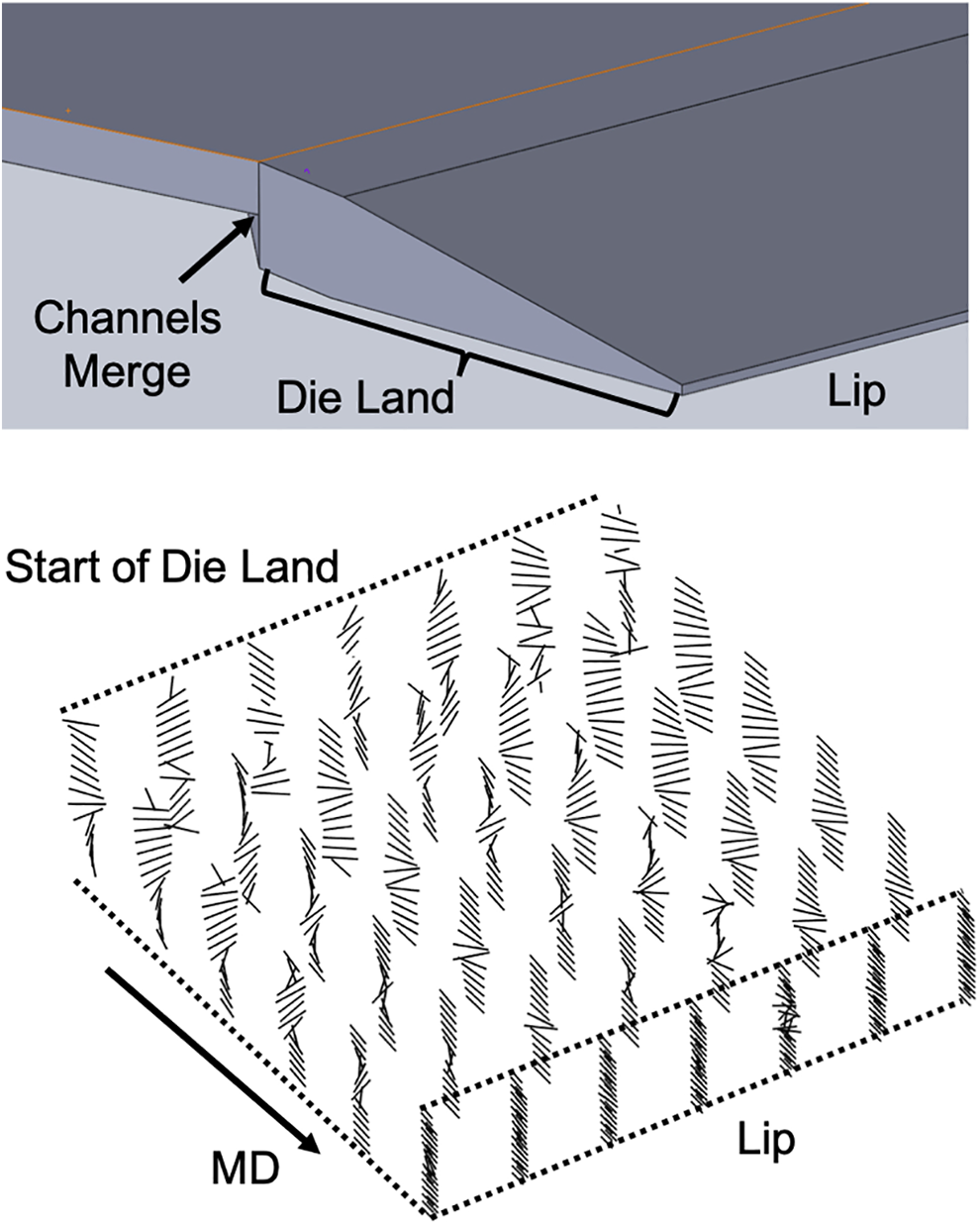
Director field in a section of the crossflow die land.
Conclusions
The preferred orientation and macroscopic mechanical, thermal, and dielectric behavior, of extruded LCP film was presented in this investigation. A modeling tool was presented to predict the polymer directionality resulting from a full-scale extrusion process, and comparison was made to WAXS orientation measurements, as well as to material property ratios measured along MD and TD. It was seen that a strong correlation exists between the LCP microstructure and the macroscopic material performance, which justifies the industrial need to improve morphological isotropy during processing.
With respect to the modeling tool, the coat-hanger die simulations were found to predict both the direction and relative degree of order measured from the experimental scattering data. The validation establishes the robustness of the model across various melt-processing methods, extending previous success simulating injection molding to include cast film extrusion. Additionally, consideration of two alternative die designs demonstrated a practical implementation of the tool to simulate directionality in complex, full-scale processing geometries. It was found that although the “active” regions of both designs altered the preferred director orientations, the dies ultimately fell short of improving the final film isotropy, thus highlighting the pervasive difficulty of producing isotropic LCP film through static die geometries. Nevertheless, the analysis illustrates the value of the modeling tool to simulate proposed process modifications prior to spending time and money to develop the actual tooling. The collection of simulations, scattering measurements, and material testing presented in this investigation provide broad insight into the LCP film structure-property-processing relationships that are critical to driving the design of isotropic material manufacturing methods.
Footnotes
Acknowledgments
The authors would like to acknowledge iQLP and Ionic Materials, in Woburn, MA, for fabricating the LCP cast extruded film and providing the WAXS and material testing facilities used in this investigation.
Declaration of conflicting interests
The author(s) declared no potential conflicts of interest with respect to the research, authorship, and/or publication of this article.
Funding
The author(s) received no financial support for the research, authorship, and/or publication of this article.