
Abstract
In this paper, the impact response of bi-directional corrugated core sandwich structures was investigated. The core and skins were made of E-glass/epoxy laminated composites. Additive manufacturing technology was used to print the molds applied to fabricate the cores. The influence of different periods, i.e. T = 30, 37.5, 50 and 75 mm, of the double-cosine corrugated core on the impact response of the panels was evaluated. In addition, some other panels with regular corrugated cores were manufactured to evaluate the impact response of the bi-directional corrugated core structures. A finite element modeling was also carried out to analyze the impact behavior of the samples. The empirical measurements and the numerical predictions showed that the panels with the bi-directional corrugated core have a significant improvement in the absorbed energy under impact loading at each given period. It was also manifested that the panel consisting of the bi-directional corrugated core with T = 37.5 mm has the highest specific energy absorption.
Keywords
Introduction
Sandwich structures with high specific energy absorption were designed by engineers to use in various applications such as aerospace structures, military industry, rail transport, ship, building and so on. Fiber-reinforced laminated composites are lightweight materials with remarkable mechanical properties. 1 Hence, in the recent years, many researchers have focused on the designing of different patterns for the core of sandwich panels with the skins made of laminated composites.2-21 For instance, Ji et al. 5 proposed a hybrid sandwich panel consisting of hollow metallic grid reinforced epoxy system as the core and glass/vinyl ester laminates as the face sheets. The specimens were tested under low-velocity and ballistic impact testing. Dear et al. 6 studied the impact behavior of sandwich panels with different face sheets and nomex honeycomb cores. Kim et al. 7 proposed a novel technique to fabricate the sandwich panels based on the angled stitching of yarn between two skins made of E-glass/epoxy layers. The sandwich samples were tested under compression, tension and shear loadings. It was observed that the strength and stiffness of these specimens are increased as compared to the sandwich panels with honeycomb cores. Azadian et al. 8 investigated the influence of cross-sectional shape of the core on the flexural strength and stiffness of 3D integrated-knitted spacer composites. Single and double-decker U-shape, and single-decker V-shape were considered as the core of sandwich panels. It was resulted that the specimens with triangular cross-section have the highest flexural stiffness. Liu et al. 9 studied the impact response of the sandwich panels with an aluminum foam core and fiber metal laminate (FML) skins experimentally and numerically. Li et al. 10 explored the perforation response of the sandwich panels with an aluminum foam core and two laminated composites skins under low-velocity impact loading. The effect of upper and lower face sheets thicknesses, core height and its density on the energy absorption of the sandwich panels was measured. It was revealed that thicker upper skin, thicker core and denser core significantly affect the energy absorption of the panels. Xiong et al. 14 suggested two patterns for the core of sandwich panels with skins made of carbon fiber reinforcement laminated composites. Egg and pyramidal honeycomb patterns with carbon/epoxy beams were used as the cores. The experimental results manifested that the flexural strength of the pyramidal honeycomb core sandwich panels is higher than the flexural strength of the egg honeycomb core sandwich panels.
In the reference, 21 it was proved that the flexural behavior of sandwich structures with the corrugated cores strongly depends on the core arrangement. To resolve this dependency, bi-directional corrugated core panels were presented. Hence, in order to complete the research project, the behavior of the bi-directional corrugated cores sandwich structures subjected to low-velocity impact loading were explored in the current study. The influence of different periods, i.e. T = 30, 37.5, 50 and 75 mm, of bi-directional corrugated core on the energy absorption capability of the sandwich panels was evaluated. In addition, some other sandwich panels with regular corrugated cores were manufactured. A finite element modeling was also performed to investigate the effect of some parameters on the energy absorbed by the panels.
Experimental study
As observed in Figure 1, different steps must be carried out to manufacture the corrugated core sandwich panels presented in this study. Designing of the cores, printing of the core molds, manufacturing of the cores and the face sheets, and assembling of the sandwich structure components are mentioned in the next sections.

The corrugated core sandwich panels fabrication process steps.
Cores designing
In our previous paper, 21 different arrangements were proposed for the corrugated cores. The function related to the regular and bi-directional corrugated core can be expressed as follows, respectively:


where A is the cosine curve amplitude, which it is equal to 10 mm in the current study. In addition, B is a design variable that determines the wave number in 75 mm. The wave number of regular and novel corrugated cores has been summarized in Tables 1 and 2, respectively. Besides, x and y are the longitudinal and transverse directions, which 0 ≤ x, y ≤ 150 mm. Therefore, the dimensions of the cores are 150 mm × 150 mm × 20 mm. The other geometry properties of them have been summarized in Tables 1 and 2.
Configurations of the regular corrugated cores.

Configurations of the novel corrugated cores.
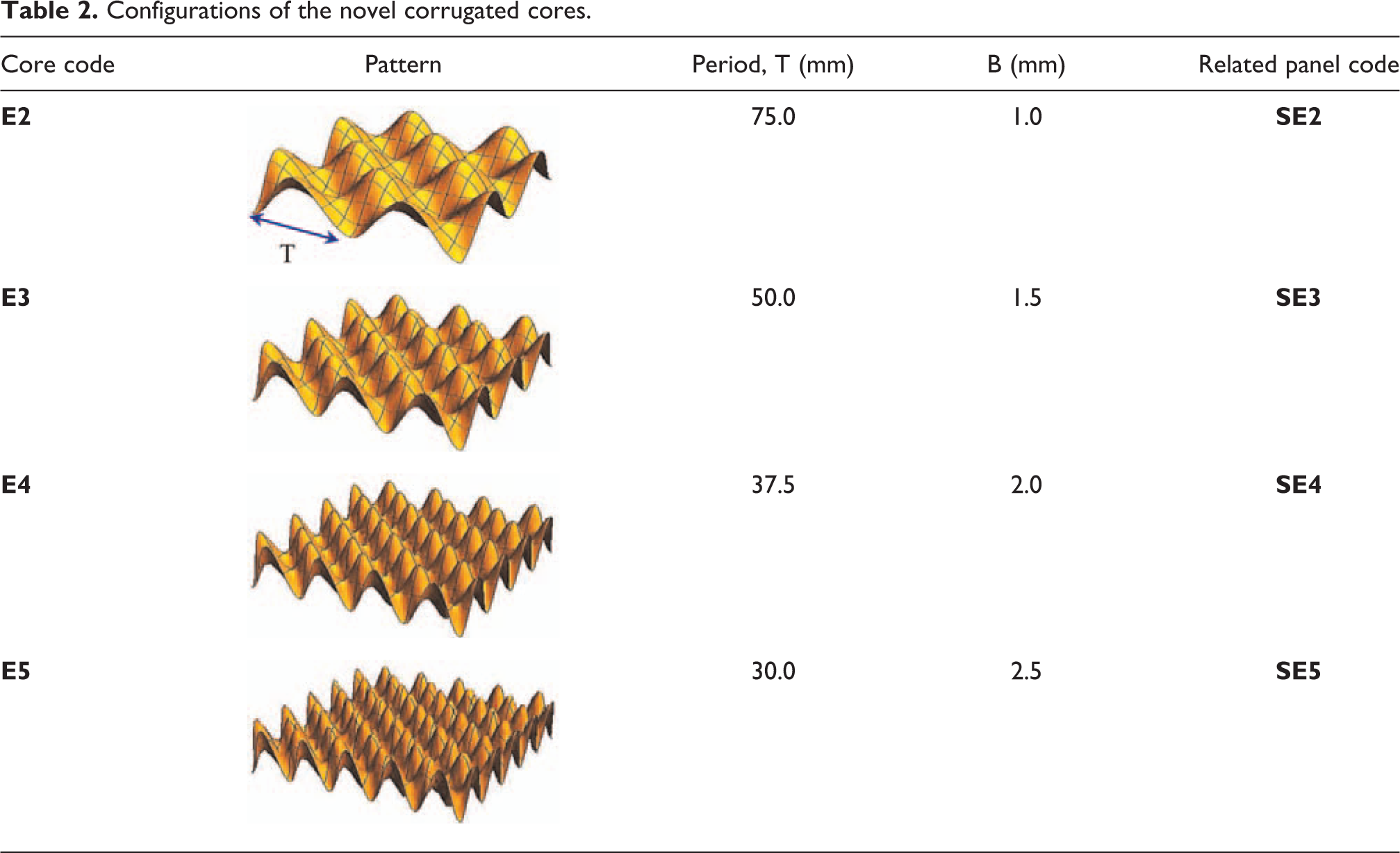
In order to fabricate the bi-directional and regular corrugated cores displayed in Tables 1 and 2, some molds must be manufactured. In the first step, the molds were modeled in CATIA software according to Eqs. (1) and (2). As observed in Tables 1 and 2, the cross-section of the molds is so complex. Therefore, in order to manufacture the molds, an in-situ 3-D printer machine was utilized. Besides, poly-lactic acid (PLA) material was utilized to fabricate the molds. It must be noted that the G-Code file was prepared using SIMPLIFY3D software (see Figure 1).
Materials selection
In this study, the core and face sheets of the sandwich panels were made of four E-glass/epoxy layers. The E-glass woven fibers with a surface density of 100 g/m2 provided by AMP Composites Co., Ltd. were chosen to fabricate the core and the face sheets. In addition, an epoxy resin (Araldite LY 5052, Huntsman) and a hardener (Aradur 5052, Huntsman) with mix ratio of 100:38 were used as the matrix of the laminated composites. The mechanical properties of the E-glass/epoxy system with the volume fraction of 44.5% measured according to ASTM D3039, 22 D6484 23 and D3518 24 are listed in Table 3. The dimensions of the tensile and shear samples are the same and equal to 1.5 × 25 × 250 mm3.

Specimens manufacturing
The core and the face sheets of sandwich panels were fabricated using vacuum bagging technique. The vacuum bagging procedure including matrix de-bulking, hand lay-up and vacuum bag closing was performed. A bi-directional corrugated core fabricated by E-glass/epoxy laminated composites has been displayed in Figure 1.
The cores and the face sheets were cured at 25°C for 6 days. After curing, the components were bonded using LY5052 epoxy resin. The average thickness of core and face sheets were obtained as 1 mm. According to the supplier, the strength and the Young’s modulus of this resin system equal to 63.4 MPa and 3.44 GPa, respectively. For each panel configuration, at least three samples were prepared to test under low-velocity impact loading. At the end, the sandwich structures were post-cured at 100°C for 4 h. Besides, using burnout test, the average volume fraction of E-glass fiber was determined as 44.5%. The weight of regular corrugated core panels, i.e. SC2, SC3, SC4 and SC5, is equal to 99.7 ± 4.0, 102.1 ± 9.3, 105.2 ± 3.9 and 110.6 ± 8.0 g, respectively. Moreover, the weight of bi-directional corrugated core panels, i.e. SE2, SE3, SE4 and SE5, is equal to 100.8 ± 4.1, 103.1 ± 4.8, 106.6 ± 7.6 and 111.2 ± 7.3 g, respectively.
Impact testing
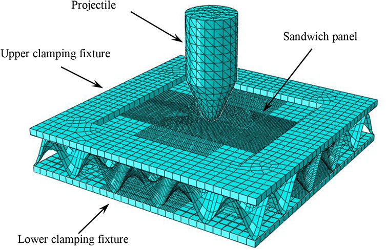
The manufactured specimens were tested under a low-velocity impact loading condition. For this reason, a drop-testing machine shown in Figure 2 was used. The sandwich panels were clamped by two square steel clamping rings with a 100 mm × 100 mm square test area. It must be noted that there is a space with a 100 mm × 100 mm square area under the samples. A total mass of 5 kg was dropped at the height of 49 cm to measure the energy absorption and the other properties of the panels under impact loading. In the other word, in this investigation an energy level of 24 J was applied to the samples. Different projectile nose shapes such as conical, ogival, flat and hemispherical have been used in the literature27,28 to apply impact loading on the samples. In the current research, an impactor with a conical nose shape made of high strength steel was considered (see Figure 2). In order to perform the impact testing, the panels were placed on the floor of the test rig. As observed in Figure 2, fully backed condition was considered to keep the samples. According to the acceleration signals recorded by the accelerometer, the change of force versus the time can be plotted.

The drop weight test machine used to determine the response of the sandwich panels under low-velocity impact loading. All dimensions shown in the projectile image are in mm.
Data reduction schemes
According to ASTM D7136, 29 the impactor velocity at time t is computed using the following formulation:

where vi is the impactor velocity when it initially contacts the sandwich panel (t = 0), which is equal to 3.1 m/s in the current investigation. Moreover, g, t, F and m are the gravity acceleration, the time during test, the recorded impactor contact force at time t and the impactor weight, respectively.
The following relation was also suggested to determine the displacement of under impact loading as a function of time 29 :

where δi is the impactor displacement at t = 0.
The main parameter in the impact testing is the energy absorption of the sandwich panels. The absorbed energy can be determined as follows 29 :

where Ea is the value of energy absorption by each sample at time t.
Numerical study
Similar to the other references, 3 in order to use the experimental results for the practical applications, a finite element analysis was investigated (see Figure 3). Hence, the numerical study was carried out using the Abaqus/Explicit software. 30 Different damage models have been developed for the laminated composites. 31 In this study, damage initiation and evolution in the sandwich panels were simulated based on Hashin failure criterion. 31 This criterion proposed the following cases to predict the damage initiation in the laminated composites:
The simulated sandwich panel with the novel core subjected to low-velocity impact loading.
Case 1: Fiber tension

Case 2: Fiber compression

Case 3: Matrix tension

Case 4: Matrix compression

where α is coefficient that determines the contribution of the shear stress to the fiber tension initiation condition. It was assumed that α = 1 in the present numerical analysis like some other studies.
32
Besides,
After the occurrence of damage initiation, damage evolution happens. 31 Subsequently, the evaluation of damage is evaluated by computing equivalent stresses and strains defined as follows26,31:
Case 1: Fiber tension

Case 2: Fiber compression

Case 3: Matrix tension

Case 4: Matrix compression

where 〈〉 denotes the Macaulay operator. For instance,
Although the application of Hashin failure criterion has been developed to unidirectional fiber-reinforced composites, in the recent years investigators 32 have used this model to predict the damage initiation of woven fiber-reinforced composites.
In this study, the core and the face sheets were meshed using four-node linear shell element type with reduced integration (S4R). Besides, element type of 10-node modified quadratic tetrahedron with reduced integration (C3D10M) was considered for the projectile and the clamping fixture. According to the practical work, a layer with the thickness of 0.1 mm was simulated as the adhesive between the core and the skins of each panel. To obtain an optimum mesh size, mesh convergence analysis was performed. At the end, the mesh size of 1 mm was chosen for the impacted region. The dimensions of the impactor were considered as shown in Figure 2. The boundary condition and the impactor velocity at the initial contact with the sandwich panel were applied according to the experimental study.
Results and discussion
Force versus time curves
Typical impact force versus contact time curves of the panels with novel and regular cores are represented in Figure 4. It is seen that the contact duration is constant and it is equal to 13 ms. As observed the general shape of the force-time history of the samples with the regular corrugated cores are the same. For all the regular corrugated core panels, a sudden drop is observed at 4 ms after the initial contact as demonstrated by a circle in Figure 4. Likewise, the sandwich structures consisting of the novel cores have a similar response (see Figure 4). It is well observed that by increasing the wave numbers, the maximum impact force obtained for the novel and regular corrugated cores enhances. Moreover, comparison between the contact force-time curves manifests that for a certain period, maximum impact force of the sample with the novel core is higher than that of the panel with the regular core.
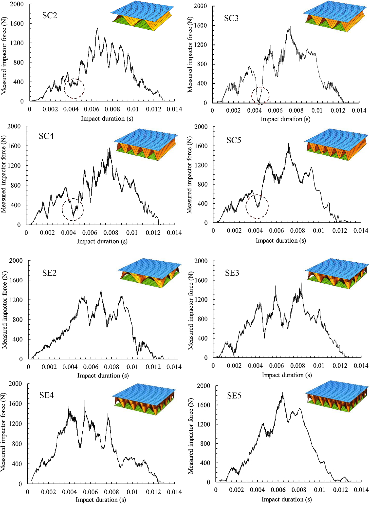
Impact load–time curves of the sandwich structures with different regular and bi-directional corrugated cores. The circle shows a sudden drop happened for every panel with regular corrugated core.
The maximum impact force of different sandwich structures has been listed in Table 4. For instance, for the panels having the core with the period of 30 mm, by changing the core pattern from the regular to the bi-directional, the maximum impact force is enhanced around 15.7%. It was found that the highest and lowest impact forces were obtained for the SE5 and SC2 panels, respectively.
Maximum deflection of the sandwich structures under low-velocity impact loading.

Deformation versus time curves
Deflection of the sandwich panels subjected to the low-velocity impact loading can be computed based on Eq. (4). In order to find out the effect of the period and the core pattern on the maximum deflection, the results have been listed in Table 4. For both panel systems, it is clearly depicted that maximum deflection decreases, as the cosine curve period is degraded. The lowest deflection was obtained for the bi-directional corrugated core sandwich panels with 30 mm.
Energy absorption
Effect of wave numbers
To evaluate the response of the novel core sandwich structures under low-velocity impact loading, the energy absorption was plotted versus the time. Moreover, the energy absorption-time curves of the regular core panels were also demonstrated. In addition to the curves illustrated based on the experimental data, using the FE analysis the impact energy-time curves were plotted. As depicted in Figure 5, the trends of the energy-time curves obtained by the experimental and numerical methods are generally the same.

Change of the energy absorbed by the sandwich structures having the regular and bi-directional corrugated core when T is equal to 75, 50, 37.5 or 30 mm versus time plotted based on the experimental (dotted line) and numerical (solid line) methods.
The specific energy absorption of the panel was also summarized in Table 5. Significant enhancement in the specific energy absorption of the panel was resulted as the core pattern is changed from the regular corrugated to the bi-directional corrugated. In addition, it is revealed that the maximum specific energy absorption is obtained for the panel consisting of the novel core with T = 37.5 mm. Likewise, among the structures having the regular cores, the maximum specific energy absorption was obtained for the sample with T = 37.5 mm.
Specific impact energy absorbed by the sandwich structures.

Effect of skins and core thickness
In order to figure out the influence of thickness of the core and face sheets, the FE analysis was utilized. Hence, in addition to thickness of 1 mm including four E-glass/epoxy layers, three other thicknesses (1.5, 2 and 2.5 mm) were considered for the core and face sheets of the SE4 specimen. Figure 6a shows the impact energy absorbed by the SE4 specimen with different thicknesses of the upper skin versus the time. It is observed that as the upper skin thickness increases, the energy absorption is also enhanced. To obtain an optimum thickness of the upper skin, the specific energy absorption curves were plotted as shown in Figure 6b. As depicted, enhancing the thickness from 1 mm to 2.5 mm does not have significant effect on the specific energy absorption. The core thickness effect on the energy absorption of the SE4 sample was illustrated in Figure 6c. It is well seen the energy absorption value is enhanced by increasing the core thickness. However, Figure 6d demonstrates that the panel with the thicker laminates core absorbed lower specific impact energy. Likewise, Figures 6e and f were illustrated to evaluate the influence of lower skin thickness on the energy absorption and its specific value. The results clarify that the energy absorption of the panel is not affected by the lower skin thickness. Besides, as the E-glass/epoxy layers of the lower face sheets are increased the specific energy absorption is significantly decreased.

Influence of (a) upper face sheet, (c) core and (e) lower face sheet thickness on the energy absorption of the novel corrugated core panel with the period of 37.5 mm (SE4) and (b), (d) and (f) its specific value, respectively.
Effect of cosine curve amplitude
The effect of amplitude value of the core cosine curve on the energy absorption of sandwich panels was evaluated. Figures 7a and b show the specific energy absorption vs. time curves of sandwich panel consisting of the regular and novel corrugated core with T = 37.5 mm and different amplitude values, respectively. As demonstrated for both panels, by increasing the amplitude value (A) from 10 to 16 mm, the specific energy absorption is significantly decreased. Obviously, by increasing the value of amplitude, the height of core and subsequently the height of the sandwich panel are increased. As observed, for the panel consisting of the corrugated core with the lower amplitude value, higher specific energy absorption was obtained. The main reason for this behavior is related to the region of core damaged by the projectile. In the other words, for the thinner core, the projectile damages the bigger region of the corrugated core. However, by increasing the core height (amplitude) the region of core damaged by the projectile is decreased. It must be noted that by increasing the region damaged under impact loading, the value of energy absorption is also increased. Similar behavior was reported by Kılıçaslan and Güden 33 for the honeycomb core sandwich panels.
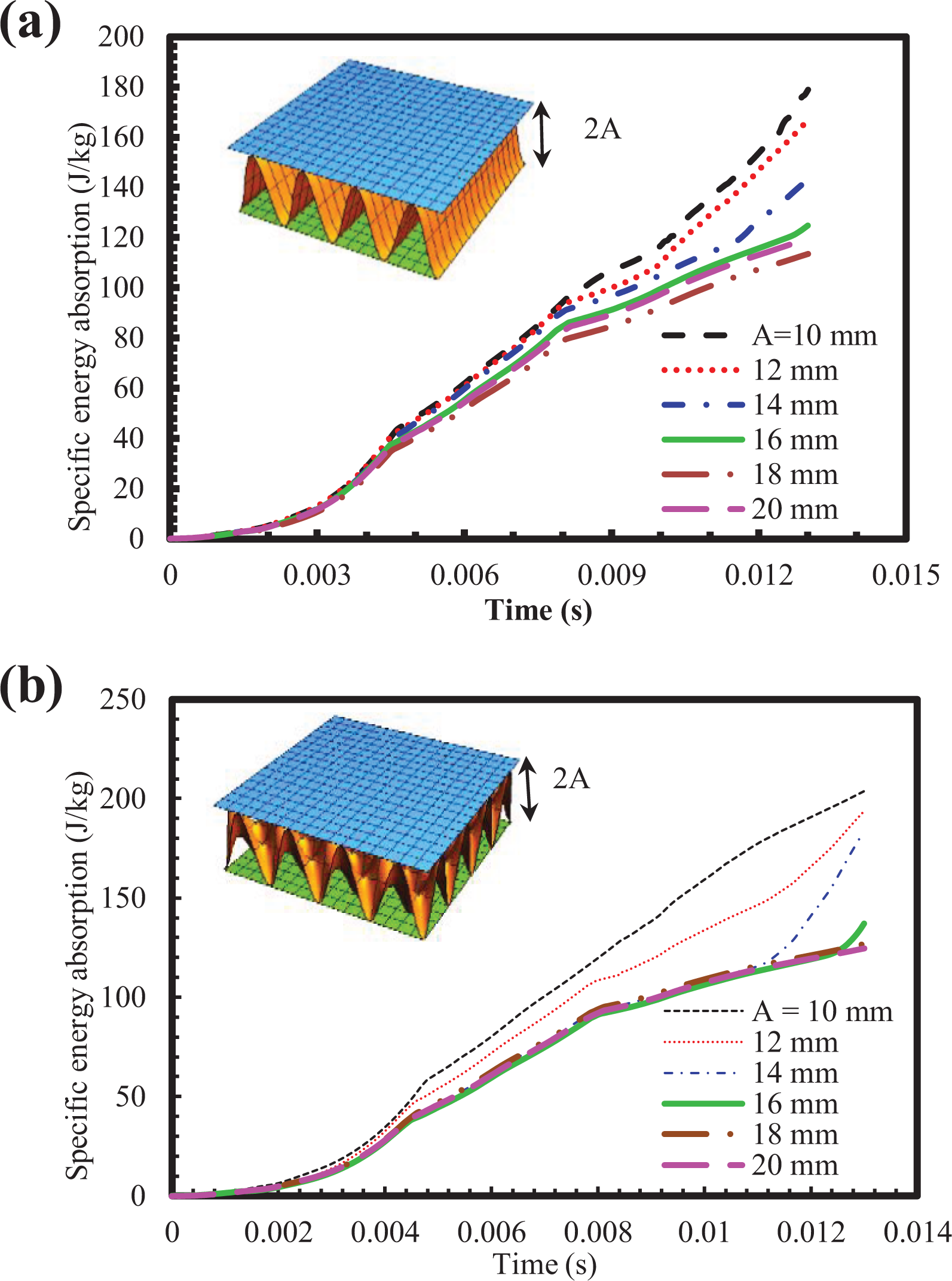
Effect of cosine curve amplitude on the specific energy absorption of (a) SC4 and (b) SE4.
Damage on the sandwich panels
To evaluate the influence of the core pattern and its period on the damages occurred in the surfaces, some images were obtained from the FE analysis. Different damages, i.e. fiber failure under tension and compression, matrix failure under tension and compression, occurred in the C4 and E4 cores under the low-velocity impact loading have been shown in Table 6. The regions with red color reveal that they are completely failed. It is clearly observed that the damages in the surface of the novel cores are significantly decreased as compared to the regular cores. It is also revealed that for each core, the matrix failure under tension is the main damage mode under impact loading as also reported by Liu et al. 28
Different types of damage occurred in the regular and novel corrugated cores with the period of 37.5 mm.

Conclusions
In this work, a bi-directional corrugated core was proposed in order to improve the low-velocity impact behavior of the E-glass/epoxy sandwich structures. The influence of different periods, i.e. T = 30, 37.5, 50 and 75 mm, of the regular and bi-directional cores on the energy absorbing of the sandwich structures subjected to impact loading was evaluated. Then, the samples were simulated in Abaqus software in order to use the novel core panels in the practical application.
– It was observed that for a certain period, the specific energy absorption of the panels is significantly increased as the core pattern is changed from the regular corrugated to the bi-directional corrugated.
– A dependency of the energy absorption on the wave numbers was revealed according to both experimental and numerical studies.
– It was also resulted that the structure consisting of the bi-directional corrugated core with T = 37.5 mm has the highest specific energy absorption.
– Minimum deflection under drop weight-impact loading was obtained for the sandwich panels with T = 30 mm.
– Around 5% degradation in the deflection of the samples was resulted as the core pattern changes from the regular corrugated to the bi-directional corrugated.
– According to the finite element analysis, the specific energy absorption of the sandwich structures is degraded by enhancing the core or skins thickness.
– It was observed that the cosine curve amplitude has a significant effect on the specific energy absorption of the panels.
Footnotes
Declaration of conflicting interests
The author(s) declared no potential conflicts of interest with respect to the research, authorship, and/or publication of this article.
Funding
The author(s) received no financial support for the research, authorship, and/or publication of this article.