
Abstract
A finite element model with periodic boundary conditions was developed to investigate the influence of different Z-pin parameters including diameter, spacing, and insertion angle of Z-pin on the elastic properties of composite laminates. Benchmark tests were carried out to verify the FE model and a series of parametric analyses were subsequently performed. In general, all the elastic moduli, excluding the through-thickness modulus (Ez), decreased while Ez increased nonlinearly with increasing Z-pin diameter and decreasing spacing. The reduction of Ey (transverse modulus) was approximately 40% of that of Ex (longitudinal modulus), while the reduction of Gxy is similar to that of Ex. Besides, Gxz and Gyz were reduced by approximately half of the reduction of Gxy. Although the impact of insertion angle was obvious on Ez, it was negligible on the other five moduli.
Introduction
Due to the lack of fibers in the through-thickness direction, the interlaminar mechanical properties of composite laminates are usually poorer than the in-plane properties. In order to enhance the through-thickness properties of composite laminates, Z-pinning has been widely used and proven to be effective in improving the poor impact damage tolerance and bonding properties between two layers.1-3 Research on Z-pinned composite joints also shows that Z-pin can significantly improve the joint carrying capacities.4-8 However, the in-plane properties of Z-pinned laminates would be degraded due to the defects induced by the insertion of Z-pin. 1 One of the major defects is the resin-rich region (see Figure 1) resulting from the filling of resin into the region between Z-pin and fibers which are diverted to accommodate the insertion of Z-pin. Comparing to the original laminate material, the resin has much poorer properties. Therefore, the existence of resin-rich region would have a negative influence on the moduli of laminates. Another major defect is the abovementioned diverted fibers, also known as fiber waviness. Obviously, these wavy fibers would affect the mechanical properties of the laminates. 1

Typical in-plane microstructure of Z-pinned unidirectional laminate. 9
In order to understand how and to what extent the insertion of Z-pin would influence the performance of composite laminates, an increasing number of studies on mechanical properties of Z-pinned composites have been carried out through experiments9-20 and the results showed that the insertion of Z-pin would lead to the reduction of the in-plane mechanical properties of the laminate. Chang et al. 9 investigated the in-plane tensile properties of unidirectional and quasi-isotropic Z-pinned laminates. Test results showed that both longitudinal modulus and tensile strength decreased linearly with pin volume content and pin diameter. Later, Chang et al. 11 explored the effect of Z-pin on the flexural properties of carbon/epoxy laminates. Although the Z-pin process would introduce resin-rich zone and fiber distortion damage into the [0°/90°] pattern laminate, the experimental results showed that pins did not affect the flexural modulus probably due to the modulus knockdown resulting from the crimp in the satin weave, while the flexural strength decreased as the density and diameter of Z-pin increased. Mouritz 12 found that the elastic modulus, compressive strength of the unidirectional laminate reduced with increasing volume content (0.5%, 2%, 4%) and diameter (0.28 mm, 0.51 mm) of Z-pin. Hoffmann and Scharr 13 found that both circular and rectangular Z-pin would lead to the reduction of stiffness and strength of unidirectional and quasi-isotropic laminates while the influence of the circular Z-pin was more obvious. Cui et al. 14 experimentally examined the stiffness of Z-pinned unidirectional laminates under combined transverse compression and shear load. Results showed that the stiffness of Z-pinned laminates decreased significantly in all off-axis angles (different angles representing different mixture ratios of compression and shear load).
Despite the fact that experimental study is the most reliable method to examine the in-plane properties of Z-pinned laminates, parametric analysis of the influence of different Z-pin parameters including diameter, insertion density, and insertion angle of Z-pin is very time-consuming. It is not practical to measure all the elastic properties of Z-pinned laminates, such as longitudinal modulus (Ex), transverse modulus (Ey), out-of-plane modulus (Ez), shear modulus (Gxy, Gxz, Gyz) and Poisson’s ratio (µxy, µxz, µyz) through experiments. Besides, the scatter of experimental data would sometimes cover the influence of Z-pin parameters. In addition, it is extremely difficult to measure and understand the effect of Z-pin on local stress distribution through experiments. Therefore, numerical simulations are required to estimate the influence of Z-pin parameters on the elastic constants of Z-pinned laminates in depth. Steeves and Fleck 10 used a 2D FE code to investigate the in-plane compressive properties of unidirectional carbon-epoxy laminates. In this model, fiber waviness and resin-rich region were taken into consideration, while the Z-pin was replaced by resin to simplify the model. Besides, the boundary conditions imposed on the unit cell were simplified by applying compressive load symmetrically to the specimen and constraining three degrees of freedom to prevent rigid body translation and rotation. Grassi et al. 21 built a unit cell model consisting of Z-pin, resin-rich region, and fiber waviness region. Although all the main features of a Z-pinned laminate were included in this model, the boundary condition was similar to that used in Ref. 10 Grassi et al. 21 numerically explored the influence of Z-pin with a diameter of 0.28 mm and volume content of 2% on the engineering elastic constants of laminates and local stress distribution. This study provided a better understanding of the stress distribution in the Z-pin and how the Z-pin changed the local stress distribution, which was difficult to be studied through experiments. Dickinson 22 used a unit cell FE model considering the features of Z-pin, resin-rich region, and fiber waviness to analyze the influence of Z-pin material, volume content, diameter, insertion angle on the engineering elastic constants of laminates with different ply stacking sequences. In Dickinson’s model, 22 a known macro-stress was applied to the unit cell boundary to simplify the periodic boundary condition and the unit cell was constrained to deform a certain shape at the boundaries. Recently, Pierreux et al. 23 presented a computational approach to generate a structure of Z-pinned laminate consisting of Z-pin, resin-rich zone, and fiber waviness. Periodic boundary conditions were applied while only the influence of stacking sequence and Z-pin content was examined. It could be seen that the parametric study of the Z-pin parameters including diameter, insertion density, and insertion angle on the elastic properties of laminates through a proper model is still limited.
Therefore, in the present contribution, a proper periodic unit cell model of a Z-pinned unidirectional laminate including the features of fiber waviness, resin-rich region, Z-pin, and the unreinforced region was presented. Besides, periodic boundary conditions were applied. The influence of Z-pin diameter, insertion density (Z-pin spacing in this work), and insertion angle on the elastic properties of unidirectional laminates was examined quantitatively to provide a more reliable and comprehensive understanding on the changing trend of each elastic property against Z-pin parameters.
Finite element model
Selection of the unit cell
Figure 2 illustrates the microstructure of Z-pinned unidirectional laminates that contain 5 × 3 unit cells. After Z-pins with row spacing L and column spacing S are inserted into the laminate, an eye-shape zone would be formed around each inserted Z-pin. When the Z-pin spacing is small enough, i.e. S is smaller than the length of eye-shape region l, resin-rich channel would be formed along the fiber direction of the laminate (see Figure 2 (b)). For both the abovementioned conditions, the whole structure can be formed by copying and translating any one of the 5 × 3 unit cells in Figure 2. Therefore, a repeated unit cell (i.e., RUC) with length S and width L was selected to establish the FE model in this work. In order to study the elastic properties in the thickness direction, a 3D model is required. This means a thickness value should be assigned to the unit cell. Because this work was mainly focused on the unidirectional laminate, any value of thickness can be assigned to ensure periodicity. As an example, the unit cell thickness T was assigned to be equal to the thickness of the prepreg herein. Obviously, the chosen RUC is periodic in 3D space and periodic boundary conditions should be applied.

Multi-cell models with 5 × 3 repeating unit cells (RUCs): (a) RVEs with eye-shape resin-rich regions; (b) RVEs with resin-rich channels.
Fiber waviness and resin-rich region
In order to alleviate the effect of Z-pin insertion, the in-plane fibers are separated to make space for the Z-pin. The influence of the inserted Z-pin on the fibers around Z-pin is shown in Figure 3. For a Z-pinned laminate with Z-pin diameter D and spacing L × S, the influenced region is restricted in the rectangle with a length of l and width of w. Orientations of the fibers outside this region were not affected by the Z-pin. Obviously, the angle between the deformed fiber and the longitudinal direction reaches the maximum αmax on both the edges of the eye-shape resin-rich region. The orientation of deformed fiber is related to its coordinates. Thus, it can be assumed that the angle α is a function of the in-plane coordinates (x, y) with the following boundary value conditions:


Illustration of in-plane fiber waviness.
It could be assumed that the fiber orientation is symmetric about the x-axis. Therefore, angle α can be described as

where a is an unknown coefficient.
In Eq. (2), |α| increases when |x| increases or |y| decreases. This is in accordance with the variation of fiber orientation shown in Figure 3. Substituting the boundary value conditions in Eq. (1) into Eq. (2), the following equations can be derived


where αmax can be approximately expressed as

Bianchi and Zhang 24 reported that the length of fiber region l influenced by Z-pin was usually four to six times of the Z-pin diameter D. Therefore, l was assigned to be 5D in this study. Chang et al. 9 observed that the width of the fiber region w influenced by Z-pin was approximately 0.8 mm and 1.5 mm for Z-pin with diameters of 0.28 mm and 0.51 mm, respectively. Thus, the corresponding width was considered and utilized in this work.
In order to define the orientations of fibers in the FE model, an in-house program was developed and used. Taking the fibers in the first quadrant of Figure 3 as an example, if the radius of the eye-shape arc is R, the following equation can be formed:

in which, l = 5D, thus

Therefore, the eye-shape arc equation can be described as

The regions of the first quadrant can be given as follows


In this way, the orientations of fibers in this quadrant can be defined using Eqs. (3) and (4) in accordance with the nodal coordinates of the elements. The orientations of the fibers in the other three quadrants can be described in a similar way. Thus, the orientation of each element in the ABAQUS model could be assigned a rotation angle according to its coordinates to reflect the influence of the fiber waviness.
Periodic boundary condition
In this study, the periodic boundary condition derived by Xia et al.25,26 was used. For the cubic unit cell shown in Figure 4, the displacement field on the boundary can be expressed as
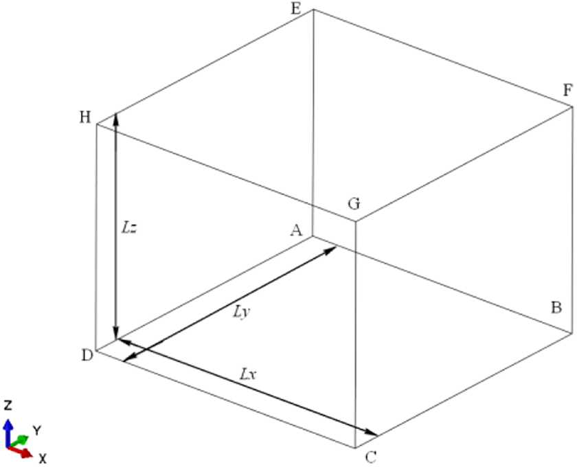
A cube unit cell.

where


where “j+” represents the boundary surface of which the exterior normal vector points to the positive axis, “j−” denotes the surface of which the exterior normal vector points to the negative axis. The unknown function

in which,
As such, Eq. (11) can then be applied to the FE model. Herein, an in-house program was developed to achieve the establishment of periodic boundary conditions between each pair of nodes on the boundary. In this work, displacements and rotations of the cubic unit cell in Figure 4 were restricted properly on vertexes A, C, D and H


where ux, uy and uz are the displacements along x-, y- and z-axis respectively, urx, ury and urz denote the rotations about x-, y- and z-axis, respectively.
Displacement loads are applied on the corner nodes. The axial load in the x-, y-, and z-axis directions can be formed by applying displacement on vertex A along the positive x-axis direction, displacement on vertex A along the positive y-axis direction, and displacement on vertex H along the positive z-axis, respectively. The shear load can also be formed by applying displacement on a certain vertex of the unit cell. The shear load on the x–y plane, x–z plane, and y–z plane can be imposed by applying displacement on vertex A along the positive x-axis, displacement on vertex H along the positive x-axis, and displacement on vertex H along the positive y-axis, respectively.
Modeling and simulation
Mechanical properties of composite materials
The prepreg used in this study was made of T700/QY8911-IV with ply thickness of 0.2 mm. The resin-rich region was filled with bismaleimide (BMI) resin QY8911- IV, the elastic modulus and Poisson’s ratio of QY8911- IV were 4.50 GPa and 0.37, respectively. Z-pin was made of T300/NHZP-1 that is a kind of BMI resin developed by Nanjing University of Aeronautics and Astronautics for Z-pin use only. The mechanical properties of the raw materials for prepreg and Z-pin are given in Table 1.
Properties of T700/ QY8911-IV and Z-pin.

Unit cell model
The Z-pin parameters that were studied in this work include Z-pin diameter, spacing, and angle. Z-pins with diameters of 0.3 mm and 0.5 mm that are widely used in research were considered. 1 It should be mentioned that for convenience the Z-pin density in this work was defined as Z-pin spacing, i.e. row spacing L or column spacing S, rather than Z-pin volume content presented in most of the literature, as the engineers think it is inconvenient for either understanding or manufacturing if the Z-pin inserting density is defined by volume content in practice. Five different spacings (i.e., L/S) including 5 mm, 4 mm, 3 mm, 2 mm, 1.5 mm were studied (see Figure 5 and Figure 6). The first three spacings were the most widely used ones in the research and 1.5 mm was the allowed minimum spacing during the manufacturing process. Although Z-pin was usually designed to be inserted vertically (inserting angle of 90°), the actually achieved angle was often smaller than 90° due to the instability of inserting process. 8 The average offset angles for big pins (0.51 mm) and small pins (0.28 mm) were 28° and 14°, respectively. 8 Therefore, the inserting angles of 90°, 75°, 60° with a difference value of 15° were studied herein.
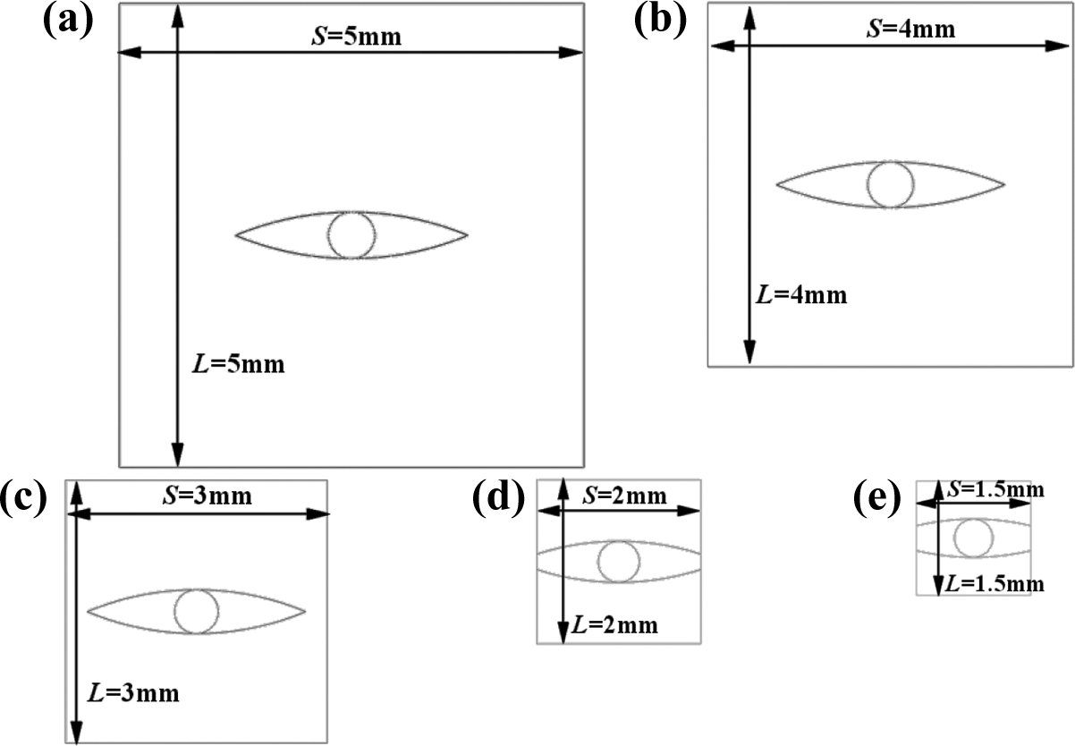
FE unit cell models of the composite laminates reinforced with Z-pin with diameter of 0.5 mm: (a) L/S = 5 mm; (b) L/S = 4 mm; (c) L/S = 3 mm; (d) L/S = 2 mm; (e) L/S = 1.5 mm.

FE unit cell models of the composite laminates reinforced with Z-pin with diameter of 0.3 mm: (a) L/S = 5 mm; (b) L/S = 4 mm; (c) L/S = 3 mm; (d) L/S = 2 mm; (e) L/S = 1.5 mm.
A mesh size of 0.04 × 0.04 mm2 and the element type of C3D8I (eight-node linear brick element with incompatible modes) were used for meshing, while only one element was placed in the through-thickness direction. The boundary conditions were imposed automatically through the in-house program. Unit cell models with inserting angles of 60° and 75° could be generated by simply transferring the nodes of the model with the vertically inserted Z-pin. This is also the reason why 3D model rather than 2D model is used.
Benchmark tests
In order to verify the FE unit cell model, benchmark tests were carried out to compare the simulation results of a certain Z-pinned unidirectional laminate with the literature data.21,22 A unidirectional laminate with Z-pin diameter of 0.28 mm, Z-pin content of 2% (i.e., L = 1.45 mm and S = 2.11 mm, the two values were given in Ref. 21 ) and inserting angle of 90° as presented in Ref. 21 was modeled. As abovementioned, a mesh size of 0.04 × 0.04 mm2 and the element type of C3D8I in ABAQUS were used for meshing, while only one element was placed in the through-thickness direction.
The obtained stress distributions of the laminate under different uniaxial loadings, i.e. x-axis tensile, y-axis tensile, z-axis tensile and x–y plane shear, x–z plane shear, y–z plane shear, were presented in Figure 7. As periodic boundary conditions were assigned to the unit cell in the model of this study, stress distributions were periodic.

Periodic stress distributions of the unidirectional laminate: (a) S11; (b) S22; (c) S33; (e) S12; (f) S13; (g) S23.
Table 2 shows the comparison between the simulation results and literature data. Most of the differences were less than 8%. It should be noted that the difference of υxz between this work and Ref. 21 was approximately 20.8%, while the difference of υxz between this work and Ref. 22 was only −5.00%. The boundary conditions of the models in Refs.21,22 were different, which indicates that boundary condition would influence the value of υxz. The boundary conditions used in Refs.21,22 were either uniform displacement boundary conditions or uniform traction boundary conditions, while the boundary conditions used in this study were periodic. In addition, the size in the through-thickness direction was much smaller than that in the longitudinal and transverse directions, the difference of υxz and υyz would be more significant than υxy, accordingly. Moreover, the modeled microstructures (fiber waviness and resin-rich region) in this work and those in Refs.21,22 may not be exactly the same. The above benchmark tests showed that the unit cell model along with periodic boundary condition in this work can be used to predict the influence of Z-pin on the elastic properties of unidirectional laminates properly. Additionally, the use of periodic boundary conditions would provide more reliable results.

Simulation results and discussion
Influence of Z-pin parameters on Ex, Ey, Ez
Figure 8 (a) shows the simulation results of the influence of Z-pin diameter, spacing, and insertion angle on Ex of the composite laminate. Both the insertion of Z-pin with diameters of 0.3 mm (netlike column in Figure 8 (a)) and 0.5 mm (solid column) would lead to an obvious decrease in Ex and the drop is more significant for Z-pin with a larger diameter. The insertion of Z-pin with a larger diameter would increase the defects (i.e., resin-rich region and fiber waviness) introduced into the laminate. The changing trend in Ex against Z-pin spacing is similar for both types of Z-pin as Ex decreases with decreasing Z-pin spacing regardless of Z-pin diameters. When the spacing is 4 mm, the decrease of Ex is less than 10%, e.g. 7.09% and 2.78% for Z-pin with a diameter of 0.3 mm and 0.5 mm, respectively. However, the reduction becomes significant when Z-pin spacing is less than 3 mm. The reason for this is that as the spacing decreases the volume content of resin with poorer properties than original laminate material increases nonlinearly. The eye-shape resin-rich regions are connected and resin-rich channels are formed when Z-pin spacing is smaller than 3 mm for big Z-pin (see Figure 5). Between the two defects, the effect of the resin-rich region should be more significant because the mechanical properties of the resin are much lower than those of the slightly curved fiber. The increasing of the resin-rich region also means the reduction of the fiber volume fraction of the laminate, which would obviously decrease the in-plane mechanical properties of the laminate. In addition, the property of Z-pin along the longitudinal direction of the laminate is also poorer than the laminate. Thus, the decreasing rate of Ex becomes greater and the difference of Ex between the laminates with different Z-pin diameters is getting more and more noticeable as the spacing decreases.

Influence of Z-pin parameters on Ex, Ey, Ez: (a) Ex; (b) Ey; (c) Ez.
As seen in Figure 8 (a), the insertion angle has a negligible influence on Ex regardless of Z-pin diameter and spacing. This could be attributed to the fact that the volume content of the resin-rich region is the same for laminates with different Z-pin insertion angles. Furthermore, the insertion angle would not change the volume content of fiber waviness region. Although the modulus of Z-pin in the longitudinal direction increases with the decrease of insertion angle, this influence is weak since the volume content of Z-pin is much smaller than that of the resin-rich region with low modulus. When Z-pins with a spacing of 1.5 mm and insertion angle of 90° are embedded into the laminate, Ex would be decreased by 15.68% and 29.32% for small and large Z-pins, respectively.
The influence of Z-pin diameter, spacing, and insertion angle on Ey is shown in Figure 8 (b). The transverse modulus is decreased due to the insertion of Z-pin. The larger pins would lead to a more significant drop in Ey, which is similar to the influence of Z-pin diameter on Ex. The decreasing rate becomes noticeable as the spacing of Z-pin reduces. An obvious reduction of Ey can be found when the spacing is smaller than 3 mm. This changing trend is similar to the influence of Z-pin spacing on Ex. However, unlike the significant drop of Ex, the reduction of Ey is mostly smaller than 10%.
The influence of the insertion angle on Ey is different from that on Ex. The transverse modulus decreases as the insertion angle decreases. The inserted Z-pin with large through-thickness modulus (Ez) would restrict the deformation of the unit cell in the out-of-plane direction. This restriction would cause resistance to the applied load and result in an effective increase in the stiffness along the transverse direction. 22 Obviously, the restriction reaches the maximum when Z-pin is inserted vertically. When Z-pins with a spacing of 1.5 mm and insertion angle of 60° are embedded into the laminate, Ey would be decreased by 6.26% and 11.36% for small and large Z-pins respectively, which are approximately 40% and 39% of the decrease of Ex.
Figure 8 (c) shows the changing trend of the through-thickness modulus (Ez) of the laminate. Through-thickness modulus is greatly improved by the insertion of Z-pin, especially for laminate with larger pins. The laminates with larger pins show a relatively higher Ez. The difference of Ez between laminates with small pins and large pins becomes more obvious as Z-pin spacing decreases. This can be ascribed to the fact that the volume content of Z-pin with relatively higher modulus in the through-thickness direction increases nonlinearly with increasing Z-pin diameters. Besides, the modulus of the resin-rich region is not obviously lower than Ez of the original laminate material.
The changing trend of the through-thickness modulus against Z-pin spacing is similar for both types of Z-pin. As the spacing decreases, Ez increases nonlinearly. This can be ascribed to the fact that the volume content of Z-pin with high modulus in the through-thickness direction increases nonlinearly with the decreasing of Z-pin spacing. The increase of Ez tends to be significant when the spacing is lower than 3 mm, which is the same point when Ex and Ey encounter a sharp drop. In addition, the insertion angle would have a potent influence on Ez as the through-thickness modulus of Z-pin decreases when the Z-pin is offset from the vertical direction. When Z-pins with a spacing of 1.5 mm and insertion angle of 90° are embedded into the laminate, Ez would be dramatically increased by 33.43% and 97.18% for small and large Z-pins, respectively.
Influence of Z-pin parameters on Gxy, Gxz, Gyz
The impact of Z-pin diameter, spacing and insertion angle on Gxy is illustrated in Figure 9 (a). Due to the poor shear modulus of the resin, the insertion of both types of Z-pin with a diameter of 0.3 mm and 0.5 mm would lead to the decrease of Gxy and the influence of large pins would be more significant. The change in Gxy with Z-pin spacing is similar for both types of Z-pin and follows a similar tendency of that for Ex against Z-pin spacing. The decreasing rate becomes more noticeable as the spacing of Z-pin reduces. The drop of Gxy seems to be significant when the spacing is less than 3 mm that is consistent with the influence of Z-pin parameters on Ex and can be explained in the same way. Moreover, the impact of the insertion angle on Gxy can be ignored, which is also similar to its influence on Ex. When Z-pins with a spacing of 1.5 mm and insertion angle of 90° are embedded into the laminate, Gxy is decreased by 12.79% and 26.74% for small and large Z-pins that are about 82% and 91% of the reduction of Ex with the same reinforcement for small and large Z-pins, respectively. Therefore, the reduction of Gxy is similar to that of Ex.

Influence of Z-pin parameters on Gxy, Gxz, Gyz: (a) Gxy; (b) Gxz; (c) Gyz.
Figure 9 (b) depicts the influence of Z-pin parameters on Gxz. Due to the addition of resin-rich region, Gxz is decreased and the reduction is more obvious for Gxz of the laminate reinforced with large pins. Similar to the influence of Z-pin diameter on the above-discussed elastic properties, the difference of Gxz gets more significant with the decrease of Z-pin spacing. In addition, the reduction of Gxz is smaller than that of Gxy. This can be explained by the fact that the inserted Z-pin would improve the shear modulus of the laminate in the x–z plane as the z-direction modulus is significantly improved by the Z-pin. Although the influence of the insertion angle is small, this influence is slightly greater than that on Gxy. This is because Z-pin with an inclined angle would provide less restriction to the shear deformation as Z-pin is defined to be offset from the positive z-axis to the positive x-axis in the x–z plane and the shear load is formed by applying a displacement at vertex H along the positive x-axis. If the load is applied along the negative x-axis, the restriction would be greater. This is the reason why Gxz decreases as the insertion angle reduces. However, as the separated resin-rich regions would connect to form resin-rich channels for laminate reinforced with large Z-pins in a spacing smaller than 3 mm, the stress distribution would change. Therefore, the changing trend of Gxz against insertion angle is inconstant. While resin-rich channel could not be formed in all the laminates reinforced with small pins, the changing trend of Gxz against insertion angle is constant. When Z-pins with a spacing of 1.5 mm and insertion angle of 90° are embedded into the laminate, Gxz would be decreased by 7.68% and 15.4% for small and big Z-pins, respectively. The reduction is about 60% of that of Gxy.
The influence of Z-pin parameters on Gyz is shown in Figure 9 (c), which is decreased due to the presence of resin-rich region. Additionally, the reduction of Gyz is smaller than that of Gxy and is consistent with the reduction of Gxz. This can be explained by similar reasons for Gxz. As Z-pin is offset from the vertical direction in the x–z plane rather than the y–z plane, there is nearly no influence of insertion angle on Gyz. When Z-pins with a spacing of 1.5 mm and insertion angle of 90° are embedded into the laminate, Gyz would be decreased by 7.31% and 12.57% for small and large Z-pins, respectively. The reduction is comparable to that of Gxz.
Influence of Z-pin parameters on υxy, υxz and υyz
Figure 10 (a) illustrates the influence of Z-pin parameters on υxy, which is increased due to the insertion of Z-pin. The transverse deformation of Z-pinned laminate under x-axis loading is increased due to the addition of the soft resin-rich region. However, the deformation restriction would offset the softening, as discussed in Section “Influence of Z-pin parameters on Ex, Ey, Ez”. This restriction increases with the increase of the insertion angle. In addition, Z-pins offset from the vertical direction would contribute to the extra longitudinal modulus of laminate, which would reduce the deformation of the unit cell under x-axis loading and the reduction would become larger as the insertion angle decreases. Obviously, the abovementioned two restrictions have opposite reactions to the change of insertion angle. It can be observed from Figure 10 (a) that υxy decreases with the decrease of insertion angle. Therefore, the second restriction shows a dominant influence. When the Z-pin diameter increases and Z-pin spacing decreases, the volume content of Z-pin increases and the difference between the two restrictions would be more significant. This could be used to explain why the difference of υxy of the laminates with different insertion angles would become more and more obvious. The dominant effect of the second restriction can also explain why there existed an obvious drop when the spacing is smaller than 3 mm and insertion angle was smaller than 90° for large Z-pin. The restriction from the inclined Z-pin is large enough to offset the increase of υxy due to the added resin when the Z-pin spacing decreases from 3 mm to 2 mm. Besides, the transformation from separated resin-rich regions to connected resin-rich channel may also make the changing trend of υxy become inconstant. Unlike the changing trend of υxy of laminates reinforced with big pins, the change of υxy is more consistent for laminate reinforced with small pins.

Influence of Z-pin parameters on υxy, υxz, υyz: (a) υxy; (b) υxz; (c) υyz.
The influence of Z-pin diameter, spacing, and insertion angle on υxz is shown in Figure 10 (b), which decreases with increasing Z-pin diameter and decreasing Z-pin spacing. This can be ascribed to the restraining effect of Z-pin with high through-thickness modulus on the out-of-plane deformation. With the increasing of insertion angle, υxz decreases, since the vertically inserted Z-pin could provide larger through-thickness modulus than the inclined Z-pin and thus the deformation restriction is enhanced. The influence of Z-pin parameters on υyz is depicted in Figure 10 (c), which showed that the changing tendency is similar to that of υxz following the identical mechanism.
Conclusions
In this work, the influence of Z-pin parameters including Z-pin diameter, spacing, and insertion angle on the elastic properties of unidirectional laminates was investigated in a quantitative manner using 3D finite element method. Unit cell models with different Z-pin parameters and periodic boundary conditions were built and used. A series of parametric analyses were performed to estimate the influence of each Z-pin parameter. Based on the findings of this study, the following conclusions could be drawn: The diameter and spacing of Z-pin have influences on all the elastic properties. In general, with increasing Z-pin diameter and reducing Z-pin spacing, Ex, Ey, Gxy, Gxz, Gyz, υxz, and υyz decrease while Ez and υxy increase nonlinearly. When the Z-pin spacing is lower than 3 mm, the decrease of Ex, Ey, Gxy, Gxz, and Gyz becomes significant. Therefore, a minimum spacing of 3 mm is suggested to maintain the stability of the elastic properties of the laminate. Comparing to Z-pin diameter and spacing, the influence of Z-pin insertion angle is relatively smaller. While, the insertion angle has an obvious impact on Ez. For small and large Z-pins with a spacing of 1.5 mm, Ex can be decreased by up to 15.68% and 29.32%, respectively. The reduction of Ey is approximately 40% of that of Ex, while the increase of Ez could be up to 33.43% and 97.18% for small and large Z-pins, respectively. The reduction of Gxy is similar to that of Ex, while Gxz and Gyz are both reduced by approximately half of the reduction of Gxy.
Footnotes
Declaration of conflicting interests
The author(s) declared no potential conflicts of interest with respect to the research, authorship, and/or publication of this article.
Funding
The author(s) disclosed receipt of the following financial support for the research, authorship, and/or publication of this article: The financial support from the National Natural Science Foundation of China (12002315) and the Natural Science Foundation of Zhejiang Province (LQ20A020003) is gratefully acknowledged.