
Abstract
Composite material high-pressure storage vessel has been increasingly applied in the hydrogen storage industry. This study aims to establish parametric analysis of fiber wound composite vessel and investigate the stress distribution, failure mechanism as well as the burst strength. Based on the maximum strain criterion and Tsai-Wu failure criterion, the burst strength of the vessel and the failure mechanism of the cylinder segment were evaluated and studied. The stresses of the cylinder were much higher than those of the dome. The cylindrical part of the vessel is its weakest area. Matrix failure initiated at the spiral wound layer, then the accumulation of matrix failure resulted in the stiffness becoming degraded and hence fiber failure happened on the hoop wound layers. The fiber failure leaded to the ultimate failure of the vessel. The wound scheme of the outer layers also plays an important role on the load-bearing ability of the vessel. The burst strength of vessel with case-A wound was 122 MPa, while it was 91 MPa for case-B wound, about 25.4% decrease. The numerical results were compared with the burst mode studied in experiments on composite vessels and a good agreement was obtained. This study provides a theoretical foundation for safe design and utilization of composite material high-pressure vessel in the fields of hydrogen storage.
Introduction
Since environment-pollution and energy-shortage crisis increasingly arouse the attention of the international community, hydrogen is likely to be the most popular and most highly promising energy carriers in the future due to its renewable and clean characteristics. 1 The high-pressure hydrogen storage vessel is the most promising and attractive storage method among the current hydrogen storage technologies due to its technical simplicity and low cost.2,3 It could be designed flexibly with different materials, different fiber wound thickness and different ply orientations, such to achieve high stiffness and strength of the vessel structure. Therefore, to ensure reliability and the safety of utilization, it is urgent to grasp the mechanical properties such as stress–strain, the failure properties and the ultimate burst strength for an optimal design of composite material high-pressure vessel.
The design of composite containers is an essential foundational work involving the mechanical and physical properties of the material as well as the geometry of the structure. At present, many researchers have made lots of studies on the design of composite gas cylinders. 4 Park et al. 5 used ANSYS program to establish a composite gas cylinder model by calculating the parameters such as the thickness, angle and number of layers of the composite layer, and then the distribution law of the stress and strain of the gas cylinder was obtained. Antunes et al. 6 developed a parametric analysis of the composite hydrogen vessel based on the improved classical composite stacking theory and composite micromechanics. Roh et al. 7 adopted netting analysis to determine the optimal dome shape, wound angle, and helical and hoop layer thicknesses of hydrogen storage type IV tank, and predicted the performance of the composite tank subject to the operating requirements and design assumptions by finite element analysis. The analysis results indicated that the use of doilies can reduce the stresses near the dome end but the stresses at the tank shoulder are not affected. The determination of optimal fiber trajectories and suitable wound patterns of filament-wound toroidal storage tanks for gaseous hydrogen had been studied with an integral design, with which fiber trajectories were suitable to satisfy various wound patterns. 8 Leh et al. 9 investigated the optimization of the composite stacking sequence of hydrogen pressure vessel considering the mutual influences of the domes and the cylindrical part on the overall behavior, multi-sequence dome lay-up characteristics and composite damage. The optimization results showed that taking damage into account was not vital for the geometry studied while respecting the burst type of the vessel’s cylindrical shell.
The mechanical properties of the composite vessel include such as the stress–strain, progressive damage and burst failure properties, which have much effect on the load-bearing ability of the composite vessel. Wang et al. 10 predicted the ultimate strength and complex failure behaviors of the composite vessel based on the integration of material property degradation and cohesive element method. Different failure modes and the ultimate load-bearing ability of the vessel were obtained. Liu et al. 11 studied the failure properties and damage mechanisms of composite vessels. The failure of the epoxy matrix, random fiber breakage and the interface crack were discussed. Moskvichev 12 studied the stress–strain behavior of composite overwrapped pressure vessel with a metal liner, and revealed the effect of propagation of initial defects in composite shell and the critical size of the crack surface. Ramirez et al. 13 presented burst simulation performed on a type IV pressure vessel. The damage state was simulated properly and not only the burst pressure but also the safe/unsafe burst were predicted and analyzed. Gentilleau et al. 14 developed a thermo-mechanical and damage behavior law incorporating fiber strength variability and fiber volume fraction variability to dedicate to hydrogen high-pressure storage vessel modeling, taking into account the matrix damage, fiber breakage. Wu et al. 15 analyze the stress and damage of a composite pressure vessel through numerical simulations considering four failure modes. The burst pressure predicted by the fiber tensile fracture criterion was in good agreement with the maximum strain criterion. Matrix crack damages appeared easily and the sensitive position was on the dome, while fiber tensile fracture damages mainly appear in the middle part of the cylinder. Park et al. 16 evaluated the stress and crack behavior of high-pressure hydrogen vessel and provided a valid means of ensuring the safety of high-pressure hydrogen storage vessels. Liu et al. 17 predicted the failure properties and burst strength of composite cylinder with explicit finite element method. The variation of the strain and stress distribution with the internal pressure, and the damage evolution process were analyzed, respectively. Magneville et al. 18 used a thermos-mechanical behavior law for composite to simulate the burst behavior of composite tank, taking into account several physical phenomena of fiber breakage, matrix cracking, plasticity and delamination. Harada et al. 19 evaluated the burst pressures of type III composite pressure vessels considering the inhomogeneity of carbon fiber packing, based on experiment and constant stress model reflecting local damage evolution in the composite layers. Leh et al. 20 presented progressive damage model to simulated a quasistatic loading test of the pressure vessel until the dramatic failure of the vessel. The axial and radial displacements of the vessel were obtained and the safe and unsafe burst modes were predicted according to the simulation results. By using the concept of fixed damage directions, Ramirez et al. 21 simulated the mechanical behavior and the burst of hyperbaric pressure vessels based on the tensorial functions theory. Different damage modes, as well as irreversible strains and the matrix viscosity were investigated. Gentilleau et al. 22 studied the type IV hydrogen high-pressure storage vessels under thermo-mechanical loading, considering the wound angle and thickness variation in domes, thermal dependencies of mechanical and thermal material properties and damage. It found that the maximum stress always reached in the first circumferential ply in the central part of the tank. In brief, the above damage analysis provided good basic for the burst strength evaluation, which is the main aim of the damage and failure analysis of composite material high-pressure vessel.
In this research, the parametric design was proposed and adopted for modeling the fiber wound composite material high-pressure storage vessel by taking account of the geometric parameters and wound pattern schemes of the vessel. The stress distributions of the liner and the composite layers obtained by numerical results were discussed. Subsequently, a failure analysis model of cylinder was established based on the Tsai-Wu criterion and implemented to finite element analysis. The failure evolution of cylinder with different wound schemes were investigated. Additionally, the burst pressure evaluation of the vessel was carried out according to the maximum strain criterion and the failure analysis of the cylinder, respectively. Finally, the failure mode obtained by finite element analysis was compared with experimental test.
Parametric modeling of composite hydrogen vessel
The capacity and the pressure load-bearing ability of the fiber wound composite material vessel are related to the geometry characteristics, materials parameters, and the wound pattern schemes. Parametric modeling is a feasible method, which can take account of these parameters into the model. The design of the composite vessel included the material parameters, wound pattern, geometry parameters and loading parameters. Modeling the vessel by using these design parameters could facilitate the stress and burst failure analysis for the composite vessel.
Geometry parameters
The geometry characteristics of the composite vessel are illustrated in Figure 1. Wherein the main geometry parameters of the vessel: the total length of the vessel is 850 mm, the diameter of the liner is 339 mm, and the diameter of the valve is 70 mm, respectively. Due to the wound angles and wound thickness at the dome region vary as the radius of the dome, in this parametric modeling of vessel, the dome of the vessel was divided into several segments as shown in Figure 1(a).

Geometry characteristics of composite layers of the vessel: (a) geometry model and the stack sequences; (b) wound pattern of composite vessel.
Wound parameters
Plenty of experimental studies indicated that the compound wound types are more effective for the load-bearing ability than a single spiral wound for the composite vessel. Therefore, in this study, the wound patterns of the vessel were combination of hoop wound and spiral wound, which obeys the geodesic path algorithm at the curved surface. In practice, the cylinder has both hoop wound and spiral wound, while the dome has only spiral wound due to the limitation of the geometry shape. The wound pattern of the vessel is shown in Figure 1(b). Wherein the spiral angle

and the spiral angle α at the any radius R of the dome is given by

where r0 is the radius of the polar axis and R0 denotes the inner radius of the cylinder.
The thickness of the composite layer at any radius of the dome is calculated by

where h is the spiral wound thickness at the cylinder, H is the spiral wound thickness at any radius R of the dome. Therefore, the wound angle and the thickness are determined by the polar radius and parallel radius. In the model of stress-stain analysis, the wound angle sequence of the cylinder was
Material parameters
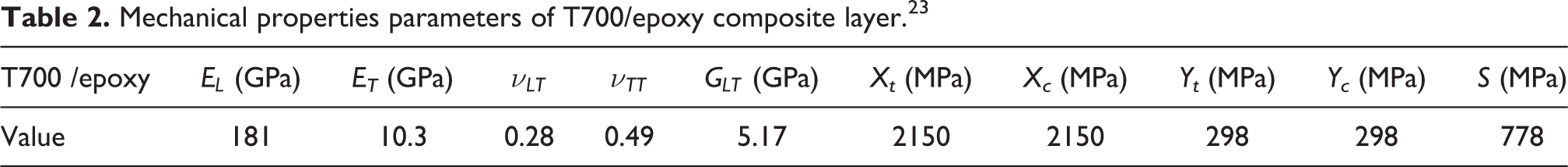
The 6061-T6 aluminum was utilized as the material of the liner, and the bilinear material hardening law was used to the calculation of the elastic-plastic behavior of the liner. The matrix was a BA202 epoxy resin system with good wettability with carbon fiber. T700 carbon fiber with a good strength performance was used for the wound fiber of the composite vessel. The carbon fiber/epoxy composites material was considered as transversely isotropic and linear-elastic material. The mechanical properties of aluminum liner and carbon fiber material were shown in Table 1 and Table 2, respectively. Wherein E denotes Young’s elastic modulus,
Mechanical property of 6061-Al T700/epoxy composite.

Mechanical properties parameters of T700/epoxy composite layer. 23
Failure and burst strength theory
Failure criteria
In the failure simulation, the maximum stress failure criterion was used for the liner, while the Tsai-Wu failure criterion was employed for the carbon fiber/epoxy composite laminates of the composite vessel. The quadratic Tsai-Wu failure criteria for 3D stress state can be expressed as the following form 24

Where

where

Where Xt and Xc are the longitudinal tensile and compressive strengths, respectively. Yt and Yc are those in the transverse direction. S is the in-plane shear strength.
Where the fiber failure condition

and the matrix failure condition:

Damage evolution
Once the above criterion is satisfied, the stiffness of the damage will degrade gradually based on the stiffness softening law of damage mechanics. The dissipation inequality for elastic material equation based on the thermodynamic theory can expressed as

where

where Fd is the damage potential function and

And the damage variable for fiber failure is defined as 25

where kf is a material constant. For matrix failure

Then the damage variable for matrix failure is obtained as

Burst strength model
Lots of burst experiments of fiber wound composite vessels indicated that, the fracture strain of spiral wound fiber is about 75 percentages of the independent fiber, while the fracture strain of the hoop wound fiber is approximate 85 percentages of that. The maximum strain criterion has been well employed to evaluate the failure strength of composite laminates. Herein, the burst strength evaluation of fiber wound composite vessel was carried out based on the maximum strain criterion, which can be expressed as26,27

where
Finite element implementation of parametric model
Algorithm of the stress and failure analysis of the model
In this study, the parametric model of fiber wound composite material high-pressure vessel was established by combining MATLAB and ANSYS. In the process of parametric modeling, the material parameters, geometric model parameters, wound pattern schemes were interactive transmitted by MATLAB codes and ANSYS Parametric Design Language (APDL). The flow chart of parametric modeling is shown in Figure 2 (a), and the failure analysis of the model is shown in Figure 2(b), respectively. In the solution algorithm of failure analysis, the failure identification and stiffness degradation were performed at each small load step. According to the failure types, the corresponding stiffness degradation schemes were performed based on the stiffness softening law of damage mechanics. Then the load increased with small increment, the calculation continued and repeated till the end of the calculation.
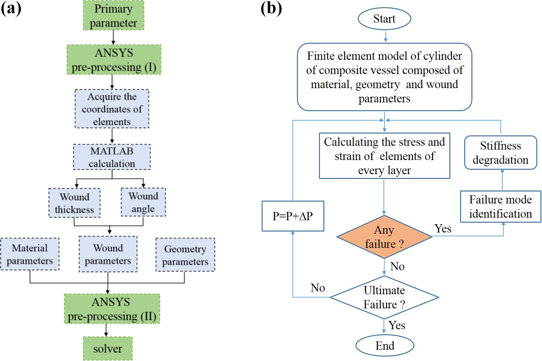
Flow Chart of the analysis of composite vessel: (a) parametric modeling of the composite vessel used for stress analysis; (b) the failure analysis for the cylinder of the composite vessel.
Finite element model of the composite material vessel
In the finite element (FE) model, the liner of vessel was modeled with solid element of solid 95, and the composite layers were modeled with solid 191, which is accurate and effective for the laminate composite materials. It should be noted that, the contact of the liner and the composite layer was supposed to be glued well in this study. The appropriate constraint conditions were applied on the vessel, and the internal pressure load was applied on the inside surface of the liner.
Results and discussions
Stress analysis of liner and composite layers
Stress along the path
The stresses distributions of the composite vessel were complex due to the particular geometry shape and the complex laminates of the vessel. In order to study the stress distribution characteristics of the vessel, the circumferential stress

The stress of composite vessel along the path A-B: (a) the circumferential stress and axial stress of the liner, the middle hoop wound layer and the outer hoop wound layer; (b) the effect of wound angle on the circumferential stress of the liner.
Stress distribution of the liner
Figure 4(a)–(b) show the stress distribution of the liner of the composite vessel. The stresses were distributed uniformly on the liner. The Mises stress of the cylinder region was higher than that of the dome as shown in Figure 4(a), while the circumferential stress of the cylinder region was more distinguish and much higher than that of dome (Figure 4(b)). It demonstrated that the cylinder segment bears the most of the pressure load while the dome bears less load under the internal pressure. The stress distributions were resulted from the deformation characteristics of the composite vessel. The cylinder region had both radical deformation and axial deformations under the internal pressure. Yet, the dome had mainly axial deformation and little radical deformation due to the its shape characteristic. The radical expanding of the cylinder resulted in circumferential tensile stress on the liner significantly. Hence, the stresses of the cylinder were much higher than those of domes.
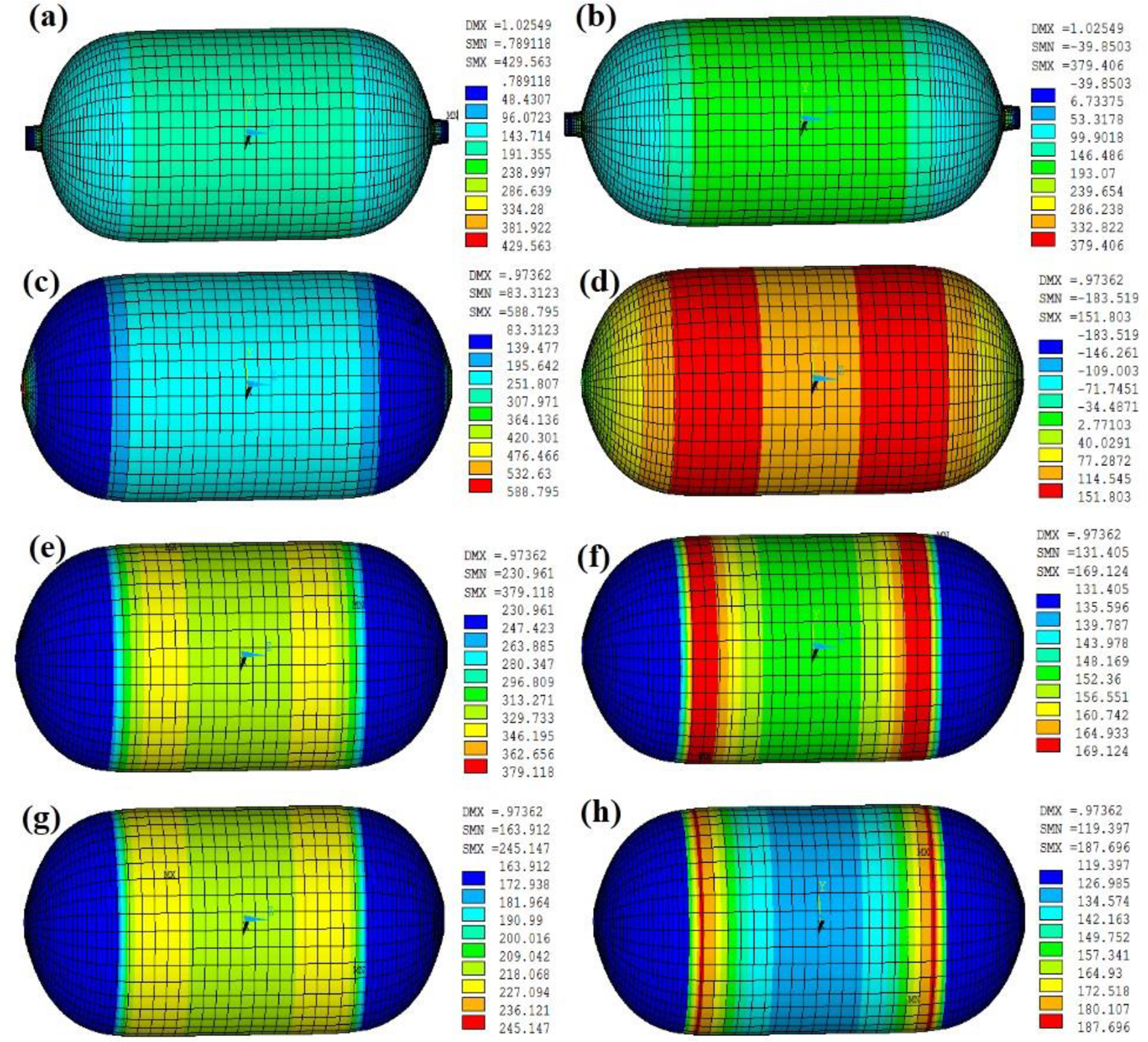
The stress distribution of liner and composite layer: (a) the Mises stress of liner; (b) the circumferential stress of liner; (c) the circumferential stress of inner layer; (d) the axial stress of inner layer; (e) the circumferential stress of middle layer; (f) the axial stress of middle layer; (g) the circumferential stress of outer layer; (h) the axial stress of outer layer.
Stress distribution of the composite layers
To a large extent, the mechanical properties of the composite vessel depend on the toughness and strength of the composite layers, which are closely related to the properties of fiber, the fiber principle orientation, the stack sequence and the geometry size. 23 Therefore, it is necessary to study the mechanical properties of the composite layers under the internal pressure. Figure 4(c)–(h) show the circumferential stress and axial stress distribution of hoop wound layers: inner layer (layer 3), middle layer (layer 5) and the outer layer (layer 10). As shown in Figure 4(c), the circumferential stress of the dome was obvious less than that of cylinder for the inner layer. Either on the cylinder or dome, the circumferential stress was relative uniform, while the axial stress distribution was nonuniform yet symmetrical along the axial direction (Figure 4(d)). The axial stresses of the transition regions between the cylinder and domes were slightly higher than that of other regions. The discrepancies of stress distributions on cylinder and dome were more distinct for the middle layer and outer layer as shown in Figure 4(e)–(h). The circumferential stress of middle layer was higher than that of the inner layer (Figure 4(e)). Figure 4(f) describes that, comparing with the inner layer, the regions with higher axial stresses were reduced for the middle layer. Nevertheless, the axial stress of the middle layer was higher than that of the inner layer. The circumferential stress of the outer layer was a little lower than that of the middle layer (Figure 4(g)). There were obviously concentrated axial stresses appeared at narrow transition region between cylinder and domes for the outer layer (Figure 4(h)). In summary, the stress distribution characteristics were related to the load-bearing percentage varying from the inner layer to the outer layer. The distributions of the circumferential stress were relative uniform while the axial stresses were gradient variation at the cylinder region. For the middle hoop wound layer, the circumferential stress was relative higher, which was resulted from the constraint from the inner layer and outer layer when the vessel expanded toward to the radical direction under the internal pressure. The outer layer had larger axial deformation, which resulted in the axial stress concentration occurred at the transition regions between cylinder and domes. However, both of the circumferential stress and the axial stress of dome were relatively lower than those of cylinder. Thus, the risk of failure of dome was relative low, while the risk of failure of cylinder was high.
Burst strength evaluation of the composite vessel
As already known from investigations that compared with the strain criterion, the stress criterion is not appropriate with respect to predicting burst pressure, which would cause the relative large error. 28 In this study, based on the maximum strain criterion, the burst pressure was determined by the fracture strain of hoop layers. According to the numerical results of finite element analysis, the maximum circumferential strain varied with the internal pressure is shown in Figure 5. The curve illustrated that when the maximum circumferential strain was 0.017, the corresponding internal pressure was 119 MPa. In other words, the fracture of the hoop wound layer would occur at that load. Hence, the burst strength was 119 MPa for composite vessel with this wound scheme. According to DOT CFFC standard that the burst pressure must be 10/3 times of the operating pressure for fiber wound composite vessel, 29 in this sense, the operating pressure of the vessel with this wound scheme would be limited less than 35 MPa.

Circumferential strain of composite layer corresponding to various internal pressures.
Failure analysis of cylinder of composite vessel
The finite element analysis results indicated that the high stress region was distributed mainly at the cylinder region of the composite vessel, while the stresses of the domes were much lower. It could be deduced that the cylinder region was the risk region of failure for the vessel under the internal pressure condition. Therefore, it is necessary to study the burst failure mechanism of the cylinder section under the internal pressure. Due to the radical load is much more than the axial load when the vessel is under internal pressure, it is assumed that the cylinder segment bears the radical load mainly and the load on the domes have less effect on the damage of cylinder. Due to the geometric symmetry of the cylinder, in this study, only one-twelfth of the cylinder section was adopted to study the failure processes in the case of the internal pressure increased and exceeded the operating pressure as shown in Figure 6. In the finite element model, the appropriate asymmetric constraints were applied on the circumferential and axial directions respectively, and the pressure loading was applied on the inside of the liner. The Tsai-Wu failure criterion was employed to the failure analysis of the cylinder. Moreover, in order to investigate the wound scheme on the burst failure properties of the composite vessel. Cylinder wound with case-A (stack sequences

Finite element model of cylinder.
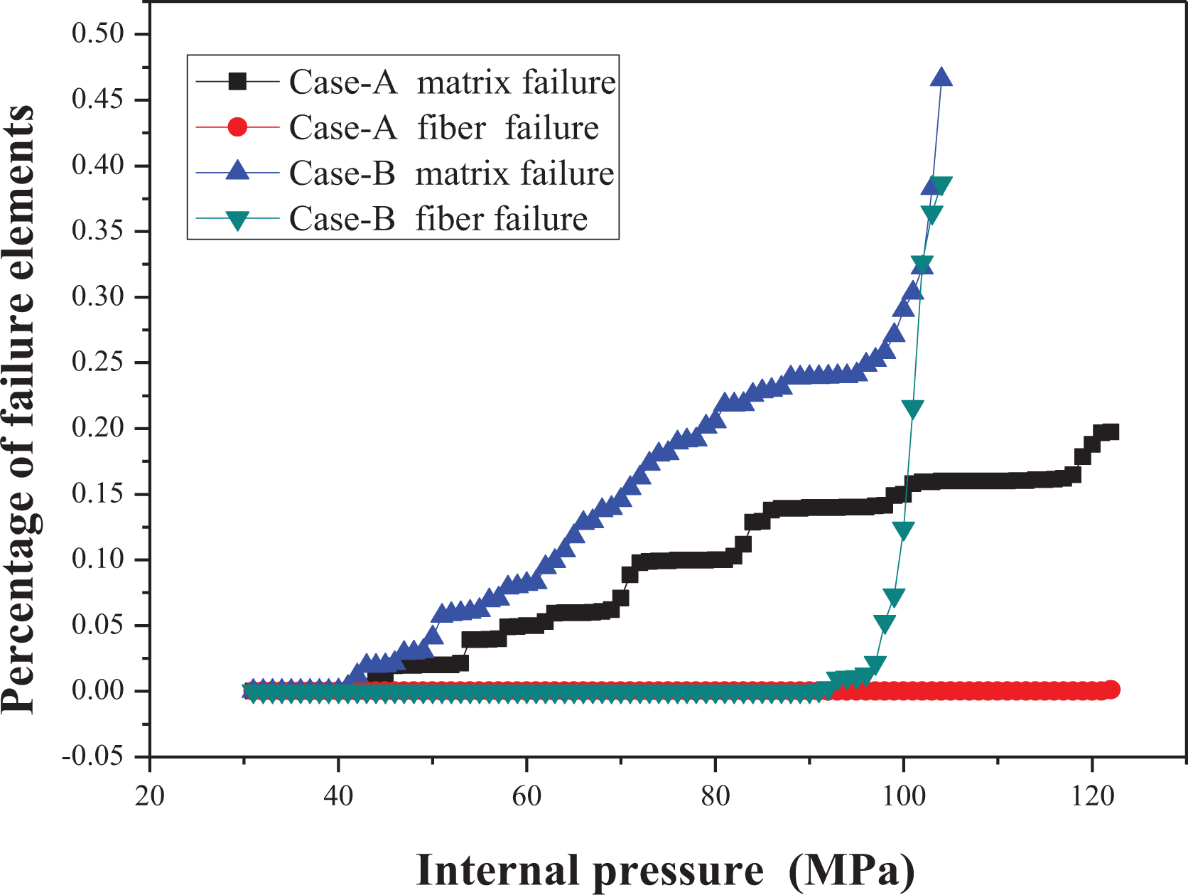
The percentage of failure elements.
Failure evolution of cylinder with case-A wound
Figure 8(a) shows the failure process of cylinder with case-A wound under the internal pressure. There was no element failed when the pressure was below of 40 MPa. The matrix failure started when the pressure increased to 42 MPa. The matrix initiation failure occurred at layer_7, which was 26.8° spiral wound layer. The failed elements appeared symmetrically at the nearby regions of the cylinder ends, which were near to the transition regions between cylinder and domes. Then the matrix failure propagated to the middle region of the cylinder gradually. Subsequently, some of the elements of the neighbor −26.8° spiral wound layer (layer_8) were also failure in type of the matrix damage when the pressure increased to 50 MPa. With the increasing of internal pressure, the matrix failure propagated to more spiral wound layers. When the pressure was more than 57 MPa, the matrix failure appeared at layer_4 (with 18.5° spiral wound) and layer_3 (with −18.5° wound) successively. After that, the matrix failure happened on the spiral wound layers increased gradually as the internal pressure increased. In spite of number of element failed in type of matrix failure, the cylinder of the vessel could continue to bear the increasing pressure loading. At the range of pressure from 57 MPa to 122 MPa, the proportion of failure element had increased from 0.049 to 0.198. When the internal pressure reached as high as 122 MPa, the fiber failure happened on the hoop wound layer (layer_2) suddenly. As is known that, the composite layers could determine to a large extent the load-bearing ability of the composite vessel due to the brittle fracture behavior of fiber. In case that fiber failure occurred at the hoop wound layer, the ultimate failure of the composite vessel would happen quickly and then the burst of the composite vessel would be prone to happen. Hence, it could be deduced that the burst would happened soon at this pressure. In this sense, according to the failure process of the cylinder, the burst pressure of the vessel with case-A wound would be 122 MPa, which was closed to the result obtained by maximum strain criterion.

The failure behavior of the cylinder with case-A wound: (a) the failure evolution (d denotes the proportion of the failure elements); (b) the number of failure element of each layer.
Figure 8(b) shows the variation of the number of failure elements for each layer of the composite layers for case-A under the internal pressure. With the loading increasing, the number of failure elements grew gradually as a platform shape. The variation trend demonstrated that, during the process of failure, the layer could continue to bear pressure load to some extend till more load resulted in more serious damage and new failure.
Failure evolution of cylinder with case-B wound
In order to study the effect of fiber wound scheme on the failure evolution process of the vessel, the cylinder with case-B wound was adopted to the failure analysis and the damage processes were shown as in Figure 9(a). There was no failure occurred when the internal pressure was lower than 39 MPa. As the internal pressure increased, the failure initiated at the 26.8° spiral wound layer (layer_7) in type of matrix damage. Then it progressed from the two ends to the middle region of the cylinder at the pressure of 42 MPa. Subsequently, the region of matrix failure extended to the adjoining −26.8° spiral wound layer when the pressure increased to 45 MPa. Similar to the case-A, the bottom spiral wound layers (layer_4 and layer_3) were failed gradually as the pressure load increased continuously, due to the deceasing of bearing ability, which was resulted from the failure of up spiral wound layers (layer_7 and layer_8). When the pressure increased to 65 MPa, most of the spiral wound layers were damage with different extent, and then more and more regions of the spiral wound layers were damage in type of matrix failure. The matrix failure means the decreasing of load-transmitting ability of matrix. Consequently, the pressure load was loaded on the fiber entirely. This resulted in the fiber damage under the increasing of internal pressure gradually. At the pressure of 91 MPa, the fiber failure appeared on the hoop wound layer (layer_2). After that, the fiber failure propagated quickly and drastically due to the decreasing of main load-bearing ability. More hoop wound layers (layer_1, layer_3 and layer_4) were damaged within a small increment of the internal pressure. Fiber failure means that the stiffness of the damage elements will degraded quickly. A plenty of fiber failure occurred at the hoop wound layers resulted in the ultimate failure of the composite vessel. Burst would happen during the process of plenty of fiber failed. Base on the analysis above, the burst strength of composite vessel wound with case-B would be 91 MPa.

The failure behavior of the cylinder with case-B wound: (a) the failure evolution (d denotes the proportion of the failure elements); (b) the number of failure element of each layer.
Figure 9(b) shows the failure elements number of each layer increasing with the internal pressure for case-B. Comparing with case-A, more layers failed in type of either matrix failure or fiber failure. The matrix failure element number increased gradually with the increasing of internal pressure. Once fiber failure of the hoop wound layer happened, more failure elements appeared and increased rapidly till the final failure of the cylinder.
In this simulation of failure evolution of the cylinder, when the internal pressure exceeded the operating pressure, the matrix of spiral wound layers began to damage in form of matrix cracking gradually, early to the initial fiber damage. The matrix damage propagated from the two ends to the middle region of the cylinder along the axial direction and then proceed to the neighbor layers. The damage of matrix accumulated gradually with the increase of internal pressure, and more load were transferred to the fiber. The ultimate failure of the vessel was resulted from the fiber damage of the cylinder segment, especially the damage of fiber in the hoop wound layers. In the experimental test, the initial damage of matrix usually happened in form of smeared cracks appeared on the cylinder, and most of the fiber failure exhibits brittle behavior. The simulation results indicate that the damage of the composite cylinder occurred layer by layer under the internal pressure. The wound angle has much effect on the burst strength of the composite vessel, and the hoop wound fiber has significant effect on the load-bearing ability of the vessel. Figure 10 shows the experimental safe burst mode of composite material high-pressure vessel. 20 It depicted that the safe burst mode was mainly the composite layers breakage occurred at the cylinder segment of the vessel along the axial direction. Based on the analysis above, the finite element analysis results of the failure of cylinder was in good agreement with the failure mode obtained by performing burst experiment of composite vessel.
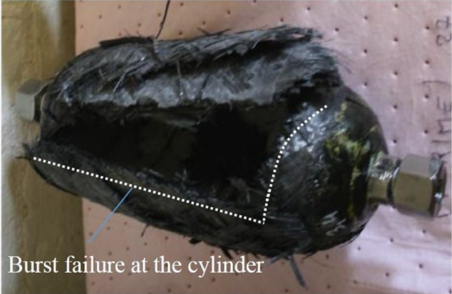
Safe burst failure mode of composite material high-pressure vessel. 20
Conclusion
A parameters model of the composite vessel was established and adopted to the finite element analysis. The stress distributions of the liner and composite layers were analyzed, respectively. Based on Tsai-Wu failure criterion, the cylinder of the composite vessel with different wound scheme was adopted to failure analysis. The failure mode of the cylinder of was verified by experimental burst mode. Additionally, the burst pressure was evaluated based on maximum strain criterion and burst failure analysis, respectively. The burst pressure obtained by the two methods were mutual corroboration with each other. The conclusions were as follows: The circumferential stress and axial stress of the liner were lower than those of the composite layers. The high stresses were distributed mainly at the cylinder section, while the stresses of the domes were much lower. There were obvious axial stress concentrations at the transition regions between cylinder and domes. The matrix failure initiated at the spiral wound layer, and then propagated to the adjoining spiral wound layer gradually. Fiber failure happened on the hoop wound layers after plenty of matrix failure of spiral wound layers. The fiber failure propagated tremendously and leaded to ultimate failure of the cylinder of the vessel quickly. The comparing of case-A and case-B demonstrated that the outer layers also plays an important role of load-bearing ability. Once fiber failure occurred at the hoop wound layer, the fiber would show brittle fracture behavior and determine to a large extent the load-bearing ability of the composite vessel, while matrix damage has a much lesser effect on the burst strength of the composite laminates.
Footnotes
Acknowledgments
Professor Liu Pengfei is thanked for the help of the modeling. Researcher Shan Zhongde, Professor Zang Yong and researcher Liu Feng are grateful thanked for the help of this work.
Declaration of conflicting interests
The author(s) declared no potential conflicts of interest with respect to the research, authorship and/or publication of this article.
Funding
The author(s) disclosed receipt of the following financial support for the research, authorship, and/or publication of this article: This study was funded by the Fundamental Research Funds for the Central Universities of China (22120180119).