
Abstract
This article presents an experimental study on the torsional behavior of composite tubes subjected to impact loadings. Four types of composite tubes with the winding angle of 30°, 45°, 60°, and 75° ([±30]FW, [±45]FW, [±60]FW, and [±75]FW) were produced with the filament winding method. Besides, a [0,90]PP composite tube was manufactured with the prepreg wrapping technique. After the composite tubes were impacted at 2.5 J, 5.0 J, and 7.5 J, non-impacted and impacted composite tubes were tested under torsional loading. Contact force–deformation curves of impacted tubes are presented. Torsional moment–twist angle relations for both impacted and non-impacted composite tubes were obtained. In addition, front view and side view of the impacted zone of composite tubes are given. The results showed that sample [±60]FW had the best impact performance with regard to absorbed energy. The impacted samples of [±60]FW and [±75]FW had the lowest torsional strength for each energy level.
Introduction
Composite tubes usually produced by prepreg wrapping or filament winding techniques have superior advantages such as high strength and lightweight when compared to the tubes made by conventional materials. 1,2 They are used in many areas such as automotive, space, aeronautical, and marine. 3,4 The most common technique used for production of hollow tubes is filament winding, because of its ability to manufacture composite tubes with high fiber volume fraction, high production speed, highly accurate fiber placement, and ease of production. On the other hand, to manufacture the composite tubes, prepreg wrapping, also known as roll wrapping, is another practical method offering various advantages such as the ability to obtain consistent mechanical properties and control a precise fiber volume fraction. 5,6
Many studies have been carried out to determine the effects of lay-up sequence, material type and winding angle on the torsional and bending behavior of composite tubes. 7 -10 Some other articles focused on hybrid reinforcement effects in filament wound hollow shafts composed of carbon, glass, and aramid fibers. 7,10 -12 Carbon–aramid hybrid reinforcements showed better density and surface hardness, while carbon fiber exhibited the best torsional resistance. Several researchers 7,13 -15 have investigated the torsional stiffness of the composite tubes with varying stacking sequence and fiber orientation angle. They reported that composite tubes with ±45° fiber orientation angle had the highest torsional stiffness. They have also found that filament wound composite drive shaft with the [±45/±45] stacking sequence has higher torsional load-carrying capacity. Furthermore, Guo et al. 16 presented the effect of filament-winding mosaic pattern on the mechanical behavior of composite cylindrical shells via finite element analysis. The results revealed that stress distributions were influenced by the size of diamond pattern units, and their numbers in longitudinal and circumferential directions.
Apart from filament winding technique, few researchers have used the prepreg wrapping method to produce composite tubes. Hu et al. 17 used unidirectional carbon fiber prepreg to manufacture composite drive shafts. The experiments revealed that stacking sequence is less effective on torsional stiffness in case of thin-walled prepreg drive shafts. Fang et al. 18 studied the mechanical behavior of fiber glass-reinforced flexible pipe (FRFP) subjected to pure torsion. The torsional rigidity of FRFP improved as the thickness of reinforced layers and radius-to-thickness ratio increased.
In addition to the torsional and bending behaviors of composite tubes, energy-absorption capacities and low-velocity impact resistances were also studied by several researchers. 4,12,19 -21 According to some researchers, 21,22 decreasing the winding angle and integrating the rubber layer into a carbon/epoxy laminate led to substantial improvements in low-velocity impact resistance. On the other hand, the addition of multiwalled carbon nanotube to fiber-reinforced plastic tubes is also found to be another useful technique to increase the maximum impact force. 23
Since impact load events are very possible during service life, the variation in residual compression and torsional properties of composite tubes occurring as a result of low-velocity transverse impact load gains importance. Deniz et al. 24 performed an experimental study and revealed that the compression-after impact strength increases as the tube diameter increases and decreases with the increase of impact energy. To investigate the torsional strength reduction because of impact damage, Sevkat and Tumer 12 produced glass/epoxy, carbon/epoxy, and carbon–glass/epoxy hybrid composite tubes. The results showed that reductions at the torsional strength decrease with the decrease of energy levels and varies with the material type. Habibi et al. 25 dealt with the after-tension impact behavior of the unidirectional flax fiber (natural fiber) composites. After-tension impact tests showed that impact damage plays an important role in tension behavior of composites and the residual strength decreases by 41% at 5 J. Henry and Mills 26 manufactured a carbon fiber composite drive shaft with the laminate [±456/±402] using the filament winding technique, and it was subjected to 252 Nm of torque during the projectile impact tests. The results revealed that a number of drive shafts did not fail at 252 Nm torque with residual torsional strength. Vashisth et al. 27 reported that that there is no distinguishable difference in residual torsional strength of carbon/epoxy cylindrical tubes with and without nano-silica filler.
Shafts, which are torque transmitting mechanical components, may be subjected to impacts caused by environmental factors and working conditions (e.g. impact of a piece of stone to the shaft or hitting of the shaft the ground.). Therefore, after a possible impact, the resultant damage on composite shafts and the load-bearing capability may be an important case that should be primarily predicted. A good number of authors have been interested in composite shafts under torsional loading or impact loading. They mainly focused on the effects of lay-up sequence, material type, winding angle, hybrid reinforcement and nanofiller on the torsional and impact behavior of composite shafts. However, few researchers focused on their post-impact behaviors. To fill this gap in the available literature, unlike previous ones, the present study is focused on the effect of manufacturing method, winding angle, and impact energy level on the residual torsional strength of composite tubes. In this study, four different types of glass fiber/epoxy composite tubes with the winding angles of [±30]FW, [±45]FW, [±60]FW, [±75]FW were manufactured by filament winding technique, and also a [0,90]PP composite tube was fabricated by prepreg wrapping technique. Composite tubes were impacted at 2.5, 5.0, and 7.5 J energy levels using a Fractovis Plus impact test machine. Afterward, impacted and non-impacted composite tubes were subjected to torsional load at a fixed angular velocity. Maximum average torsional load, maximum average twist angle, and change of torsional moment with respect to twist angle were presented for both impacted and non-impacted composite tubes.
Materials and method
Composite tube fabrication
A filament winding machine was used to manufacture the thin-walled composite tubes with winding angles of ±30°, ±45°, ±60°, and ±75°. During the winding stage, continuous fibers were first passed through an epoxy tank so as to be completely wetted. Right after that process, the wetted fibers were wound continuously around a rotating mandrel by axial movement of the fiber carrier. Rotational speed of the mandrel and angle between the axis of mandrel and the fiber carrier head are the determining factors to control the winding angle by servomotors, automatically. The thickness of the tubes is adjusted by the number of reciprocating motions of the fiber carrier. Following the winding process, composite tubes were cured at 80°C for at least 4 h. After removing the cured samples from the mandrel, they were cut into the specified test length. The length, inner diameter, and outer diameter of the tubes were 170 mm, 16 mm, and 18 mm, respectively.
The [0,90]PP oriented fiber glass–epoxy prepreg sheet, materially identical to those used in the winding method were used to produce wrapped kinds of tubes. The fiber glass prepreg was wrapped manually around the mandrel. Following a 4-h curing period performed at 80°C, the tubes were removed from the mandrel and cut into the test length of 170 mm. The inner diameter and outer diameter of the wrapped kind tubes were 16 mm and 18 mm, respectively.
The basic material properties of an identical material type to that of the current manufactured composite tube was obtained by Soykok at al. 3 through conducting standard tensile, compressive, and shear tests.
Low-velocity impact tests
Low-velocity impact tests of the composite tubes were performed at room temperature to evaluate the impact behavior of the composite tubes manufactured at different fiber orientations. The CEAST Fractovis Plus 7526 impact testing machine shown in Figure 1 was used during the low-velocity impact tests. Hemispherical impactor with a diameter of 12.7 mm and piezoelectric load cell with a capacity of 22.4 kN were used. The mass of the dropping part was 4.926 kg. The internal side of the circular support with the diameter of 76 mm was used to clamp the test specimens. To restrain the possible multiple impacts on the specimens, an anti-rebounding system was activated during the impact tests. The low-velocity impact energy levels were considered as 2.5 J, 5 J, and 7.5 J. Each energy level was implemented to specimens at least three times. Low-velocity impact test results of the composite tubes tested at different impact energy levels were interpreted with the load–deformation curves in detail.

(a) CEAST Fractovis Plus 7526 impact testing machine and (b) clamping fixture.
Torsion tests
The torsion tests performed in accordance with ASTM D5448/D5448M-11 28 were carried out to characterize the torsional behaviors of impacted and non-impacted composite tubes manufactured by both filament winding and prepreg wrapping methods. ASAHI torsion tester with a special apparatus developed for tests of hollow tubes was used (Figure 2). This apparatus prevents the sample from collapse and slippage between the metal grip and the outer surface of the composite. Detailed information about this special apparatus can be found in the literature. 3 The torsional moment applied during the tests is increased with the rate of 1 Nm/s for all samples and rotation angles are recorded simultaneously. The torsion tests were resumed until the composite tubes failed completely, so that the maximum torsional loads and the highest twist angles were recorded.

ASAHI torsion tester and special apparatus developed for mounting the test specimen.
Results and discussion
Drop weight impact tests: Force–deformation curves of the composite tubes produced at different fiber orientations and with different manufacturing methods
Contact force–deformation curves of the composite structures subjected to low-velocity impact loadings are commonly used for evaluating their impact performances. Accordingly, force–deformation curves of the composite tubes produced at different fiber orientations and different manufacturing methods ([±30]FW, [±45]FW, [±60]FW, [±75]FW, and [0,90]PP) impacted at 2.5 J, 5 J, and 7.5 J are shown in Figure 3. Only some small impact energies were applied to composite tubes since the torsion tests subsequent to impact treatment were performed to the specimens. It is seen from Figure 3 that all curves are in closed forms implying the rebounding case. When the composite tubes were subjected to impact energy level of 2.5 J (Figure 3(a)), the maximum contact force was reported as 1032 N for the sample [0,90]PP manufactured with prepreg wrapping method. Besides, the maximum deformation value for this energy level was also measured as 3.22 mm at fiber orientation of 30°. Herein, the deformation term is expressed as the range the impactor travels during the impact period. It was also noted that rebounding case was observed for this impact energy level. This means that the impactor returns back from the external diameter of the composite tubes.

Contact force–deformation curves of the composites tubes impacted at (a) 2.5 J, (b) 5 J, and (c) 7.5 J.
When the impact energy level was increased to 5 J as shown in Figure 3(b), rebounding case for all kinds of composite tubes was obtained. On the other hand, the area enclosed by the curve gets wider with the increasing applied impact energy level. The area under the closed curve is identified to be equal to the absorbed energy. Moreover, the maximum contact force and deformation values of the composite tubes increased with the increase of impact energy level. Deniz et al. 29 investigated the impact behaviors of E-glass fiber and epoxy resin-based composite pipes consisting of six layers with ±55° winding angles. They obtained that maximum deflection of the composite pipes increases by increasing the impact energy level from 5 J to 10 J. The presented results in this study are consistent with the previous study. The maximum contact force was obtained for the sample [0,90]PP at this impact energy level.
The maximum contact force–deformation curves for the composite tubes impacted at 7.5 J are composed in Figure 3(c). Partial fiber failures and matrix cracks have occurred at this energy level. When the figure was carefully analyzed, rebounding case was observed again. Maximum and minimum contact forces were obtained for the samples [0,90]PP and [±75]FW, respectively. At this juncture, it was noted that the peak force of the composite tubes increased by increasing the applied impact energy level from 5 J to 7.5 J.
When the contact force–deformation curves of the composite tubes impacted at 2.5 J, 5 J, and 7.5 J were analyzed together (Figure 3), the maximum bending stiffness of the composite tubes impacted at all impact energy levels were obtained for the sample [±60]FW. Herein, bending stiffness of the composites was calculated as the slope of the ascending section of loadings during the impact phenomenon. It is also obvious that the maximum and minimum contact forces were obtained for the samples [0,90]PP and [±75]FW, respectively. It can be also said that absorbed energy of the specimens increased with the increase of the impact energy level. Mokhtar et al. 21 have studied the impact performances of the composite tubes with four different winding angles (45°, 55°, 65°, and 75°) subjected to various impact energies. They showed that maximum contact force and absorbed energy values of the composite tubes are obtained with fiber orientation of 65°. Our results are compatible with their results. Among the composite tubes, the best impact performances in terms of absorbed energy were found at winding angle of 60°.
Torsional loading of the tubes
First, non-impacted samples were tested under torsional load to assess the negative influence of variable-speed drop weight impacts to be applied to remaining samples. From Figure 4 which gives the torsional moment–rotation angle graphs of non-impacted samples, it can be observed that the [±75]FW and [0,90]PP samples have lower torsional strengths and stiffnesses than other three sample types. However, the curves of the other [±30]FW, [±45]FW, and [±60]FW samples are very close to each other, and their stiffness and strength values are relatively high. For instance, the stiffness and strength of the tube [±60]FW are about 74.3% and 25.2% higher than those of the tube [±75]FW. This fact suggests that the use of the winding angle values between 30° and 60° in rotating power transmitting elements is favourable. 3 Zorica et al. 30 also obtained the best results for the shafts with the fiber angle of ±45° in terms of torsion angles and torsional strength.

Torsional moment–twist angle curves obtained from the torsion tests of tubes with different filament winding angles.
After being exposed to 2.5 J drop weight impact tests, the impacted tubes were subsequently subjected to torsional tests at a constant rotation speed. Figure 5 gives the average torsional moment values obtained by averaging the four repeated test results for each twist angle. It is observed that the slopes of curves related to the 2.5 J impacted specimens with the winding angles of 30°, 45°, and 60° are very close to each other, however clearly higher than that of other two sample types. This case is similar to those obtained from non-impacted samples (Figure 4). The first three filament winding patterns give the best results in terms of the maximum average torsional stiffness even after being damaged by low-level impact load. It should also be noted that [0,90]PP sample has the lowest value of torsional stiffness. It can also be said that the difference between the torsional stiffness with respect to the filament winding angle has not changed significantly when the graphs of non-damaged and 2.5 J damaged samples are compared.

Torsional moment–twist angle curves obtained from the torsion tests of tubes with different filament winding angles after exposure to a single 2.5 J impact.
When the impact energy is increased to 5 J, [±30]FW, [±45]FW, and [0,90]PP samples retain their torsional stiffness levels as well as the status of the curves relative to each other in relation to the non-impacted samples (Figure 6). However, in both the [±60]FW and [±75]FW samples, the torsional stiffness is observed to be reduced markedly compared to the non-impacted ones. It is possible to explain this situation that the same impact energy is relatively more destructive on the samples with two specified winding angles. When the impact energy is increased to 7.5 J (Figure 7), the torsional stiffness reduction in the [±60]FW and [±75]FW samples becomes more evident, while the decrease in the remaining samples is still not remarkable just like those of other impact energies.

Torsional moment–twist angle curves obtained from the torsion tests of tubes with different filament winding angles after exposure to a single 5 J impact.

Torsional moment–twist angle curves obtained from the torsion tests of tubes with different filament winding angles after exposure to a single 7.5 J impact.
It is possible to deduce from Figure 8 that the maximum twist angles exhibited by the samples before complete damage are dependent on their winding designs. Among the non-impacted specimens, the minimum angle of rotation was detected at [±30]FW and [±60]FW specimens as around 0.44 rad, whereas it was slightly higher at [±45]FW and [±75]FW specimens, of which rotation angles have nearly reached to 0.54 rad. However, the highest rotation angle measured from the samples before the damage was 1.09 rad at [0,90]PP non-impacted samples. This can be regarded as a consequence of the suitable situation of fibers oriented in the direction of both 0° and 90°, which facilitate angular deformation and allowing a certain amount of angular rotation. In addition to that, the level of impact energy that the sample is subjected to prior to torsional tests substantially affects the maximum rotation angle. After being exposed to 2.5 J impact, the average maximum rotation angles of all sample types have declined to almost half of the non-impacted ones. Subsequently, it is observed for all sample types that the gradual increase of the impact energy adversely affects the maximum twist angle. This adverse effect is maximally detected at [0,90]PP, [±75] FW, and [±45]FW samples, respectively.

The variation of maximum average twist angles with respect to the sample type and drop weight impact energy.
The most robust design in terms of maximum torsional moment for non-impacted tubes is found as [±45]FW samples with an average of 98.8 Nm maximum torsional load bearing capacity (Figure 9). For the remaining winding angles, the average maximum torsional loading capacity of non-impacted samples decreases gradually, and it is obtained as 81.4 Nm, 74.9 Nm, 57.7 Nm, and 42.6 Nm from the samples [±30]FW, [±60]FW, [±75]FW, and [0,90]PP, respectively. After the exposure of 2.5 J impact load, significant reductions in maximum torsional moments were detected for all sample types. In comparison to the standard non-impacted samples, the maximum degradation after 2.5 J impact was calculated as 59.9% at [±45]FW. On the other hand, the [0,90]PP sample was the least deteriorated sample type with a 3% reduction at this energy level. It should also be noted that the torsional strengths of the tubes prior to impact exposure was significantly dependent on the winding angle and there were substantial discrepancies between them, whereas the variation between the average maximum damage loads after the impact of 2.5 J reduced to only 10 Nm moment range. Consequently, the enormous influence of the winding angle on the allowable maximum torsional load is no longer present. When the impact energy is increased step by step to 5 J and 7.5 J, it is seen that torsional loads gradually decrease even more. Sevkat and Tumer 12 also reported that an increase in impact energy levels resulted in a 34–67% and 30–67% reduction in maximum torque and maximum twisting angle, respectively. The lowest torsional strengths in the impacted samples for each impact energy level are obtained from the samples of [±60]FW and [±75]FW, while [0,90]PP sample was recorded as the minimally affected design.

The variation of maximum average torsional load with respect to the sample type and drop-weight impact energy.
The front and side views of the impact zones of different types of samples exposed to 2.5 J, 5 J, and 7.5 J impacts are shown in Figure 10, Figure 11, and Figure 12, respectively. Observing the [±30]FW sample, a delamination based slight local colour change is observed in the affected zone after 2.5 J impact. Relatively, this area is slightly widened after 5 J impact, and this apparent damage emerges in a further expanding area with superficial cracks after 7.5 J impact. For [±45]FW samples, there is almost the same situation as observed on [±30]FW and a similar visual change on surface according to the applied impact energy.
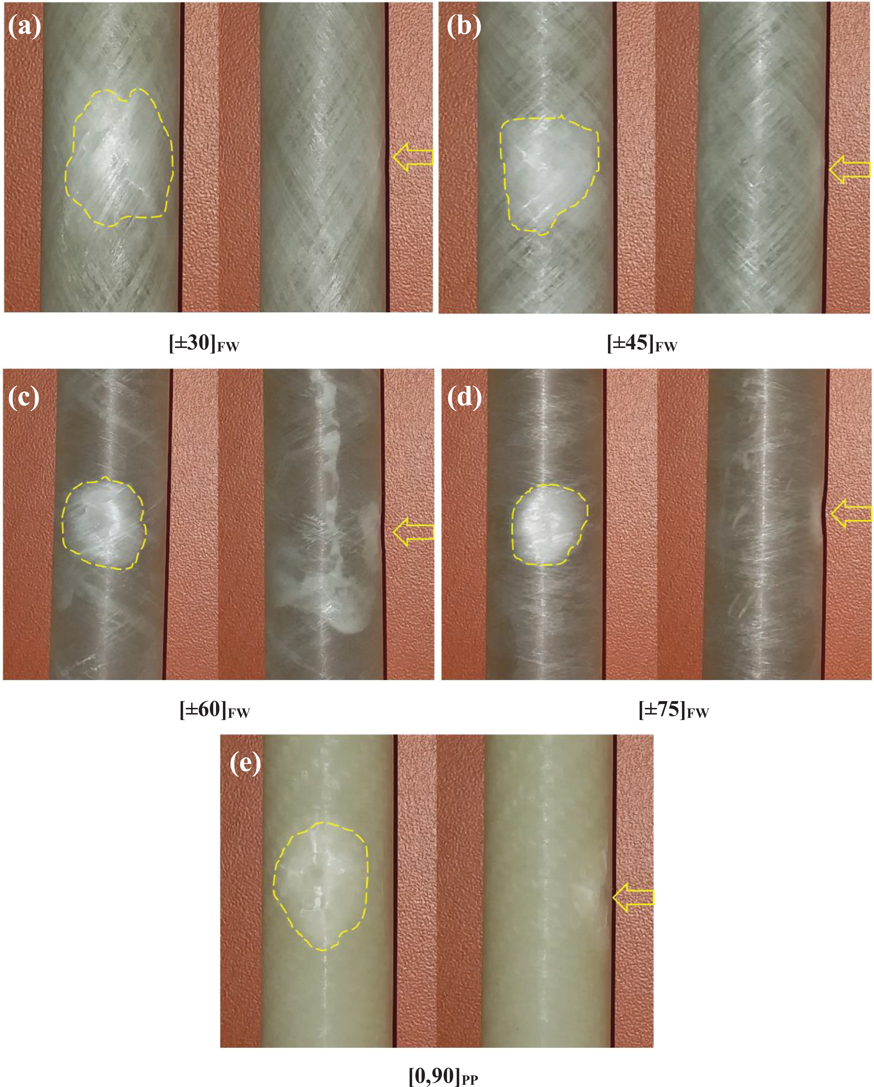
Front and side views of the impact zone on the samples subjected to impact energy of 2.5 J before torsion test: (a) [±30]FW, (b) [±45]FW, (c) [±60]FW, (d) [±75]FW, and (e) [0,90]PP.

Front and side views of the impact zone on the samples subjected to impact energy of 5 J before torsion test: (a) [±30]FW, (b) [±45]FW, (c) [±60]FW, (d) [±75]FW, and (e) [0,90]PP.

Front and side views of the impact zone on the samples subjected to impact energy of 7.5 J before torsion test: (a) [±30]FW, (b) [±45]FW, (c) [±60]FW, (d) [±75]FW, and (e) [0,90]PP.
As for [±60]FW and [±75]FW samples, in addition to the color change, some crater formation is observed as well on the surface due to piercing effect of the steel impactor tip and the depth of crater varies depending on the energy level. It is obvious that the diameter and depth of this crater is relatively higher on [±75]FW samples. It means that the increase in filament angle plays a great role in increasing the penetration effect of the impactor. In other words, a marked progress in the impact resistance can be achieved by approaching of filament winding direction to the tube axis. Maybe this can be achieved by applying the small angle reinforcements only at the outermost layers of the tube structure. The situation that the inner layers are designed as [±45]FW is more suitable in terms of torsional stiffness and strength.
Conclusions
In this experimental research, the torsional behavior of glass/fiber-reinforced epoxy-based tubes subjected to drop weight impacts were analyzed. Variable types of filament-wound samples with the angles of 30°, 45°, 60°, and 75°, and a prepreg wrap samples with 0° and 90° crosswise fibers were tested to have an insight into the effects of impact damage on the torsional behavior of tubes. The most outstanding results of all these tests can be summarized as follows: Among the composite tubes, the best impact performances in terms of bending stiffness and absorbed energy were found at winding angles of 60°. In terms of torsional strength and stiffness, the use of the winding angle values between 30° and 60° in rotating power transmitting elements is favorable. The stiffness and strength of the tubes in this range of winding angle are calculated at least 74.3% and 25.2% higher than those of the tube [±75]FW and [0,90]PP, respectively. In comparison to those of non-impacted samples, torsional stiffness of the samples with 60° and 75° filament windings was observed to be reduced markedly after being exposed to drop weight impacts, whereas the remaining samples were affected insignificantly. The reductions after 5 J impact load are measured as 40.2% and 13.2% for [±60]FW, [±75]FW specimens, respectively. Decrease in carrying torsional load capacity due to the impact was also presented in the literature.
26
In comparison to those of non-impacted samples, the maximum twist angles exhibited by the samples before the complete failure reduces sharply (up to almost half of the non-impacted ones) after 2.5 J impact load and continued to decrease gradually as the impact energy was elevated. Although the samples with 45° filament wounds had the highest torsional loading capacity among the non-impacted samples, it also has the highest decline (59.9%) in load-bearing capacity after 2.5 J impact application. However, only 3% reduction was observed at [0,90]PP. The increase in filament angle plays a great role in increasing the penetration effect of the impactor on the sample. The diameter and depth of the crater made by the impactor becomes greatest on the samples with 75° filaments, and smallest on the samples with 30° filaments.
Footnotes
Declaration of conflicting interests
The author(s) declared no potential conflicts of interest with respect to the research, authorship, and/or publication of this article.
Funding
The author(s) disclosed receipt of the following financial support for the research, authorship, and/or publication of this article: This work was supported by Manisa Celal Bayar University Scientific Research Projects Unit (BAP) (Grant Number: 2016-107).