
Abstract
In this work, composites based on linear low-density polyethylene and maple wood fibers with and without surface treatment with maleated polyethylene (MAPE) were prepared by dry blending, followed by rotomolding to study the effect of particle size, fiber content, and surface treatment. From the samples produced, a complete characterization of the morphological and mechanical properties was performed. The results obtained showed that MAPE surface treatment improved the fiber–matrix interface quality, which improved the homogeneity, the thermal stability, and the mechanical properties of the composites. The results showed that the effect of particle size was significant as the tensile modulus increased by 7%, 40%, and 73% for 125–250, 250–355, and 355–500 µm at 30 wt% of maple fibers. The tensile strength also increased by 114% at the same fiber loading (30 wt%) when the particle size increased from 125–250 µm to 355–500 μm. Finally, the impact strength with 355–500 µm particles was 52% higher than for 125–250 µm particles at 30 wt%
Introduction
Natural fibers like flax, hemp, jute, sisal, kenaf, coir, kapok, banana, henequen, and many others attracted recently the attention of researchers and scientists in producing composites with thermoplastic matrices because of the advantages they can provide over conventional fibers like glass and carbon. This is not only because of their low cost but also because they use less energy to be produced while being renewable and biodegradable. 1 -3 The so-called natural fiber composites (NFCs) are now being used for applications in leisure, construction, packaging, and automotive industries. 1 Unfortunately, natural fibers are hydrophilic, while most thermoplastic matrices are hydrophobic. This results in poor interface quality leading to low mechanical properties of the final products. 4 -8 But compatibility improvement in NFC can be done using several methods such as chemical surface treatments, especially for rotomolding applications. 9,10 In general, fiber surface treatments was shown to improve mechanical properties, moisture resistance, and fiber distribution allowing the possibility to use higher fiber contents. 11 -13 Maleic anhydride (MA)-grafted polymers are the most widely used coupling agents for natural fibers. In this case, the MA groups react with the hydroxyl (OH) groups of the cellulose (esterification), while physical entanglement can be obtained between the polymer backbone and the matrix. 10 To process NFC with coupling agents, several methods have been proposed. The fibers and the polymer matrix can be directly mixed with the coupling agents by melt blending. In this case, there is no guarantee that all the coupling agent molecules will migrate to the fiber–matrix interface and that all the fibers are evenly covered leading to some efficiency loss (mechanical and cost). 10 A more efficient method is to perform the fiber surface modification before their introduction in the matrix, especially when the simple dry blending technique is used instead of melt blending which always imposes some thermo-oxidative–mechanical degradation on both the fiber and the matrix. Recently, Cisneros-López et al., 9 Chimeni et al., 14 Verdaguer and Rodrigue, 15 and Raymond and Rodrigue 16 used a fiber surface treatment in solution to modify different natural fibers (agave, pine, hemp, and maple) with a coupling agent based on maleated polyethylene (MAPE).
It is well-known that in composites, fiber content and fiber dimensions have a direct effect on the final mechanical properties. 1,2 For NFC, Chen et al. 17 investigated the effect of wood particle size on high density polyethylene composites and reported that composites made from larger wood particles had higher strength. Nourbakhsh and Ashori 18 reported the effect of wood particle size on polypropylene composites showing that the tensile modulus was not significantly affected by particle size, while tensile strength was increased. Similar results are also available on the effect of fiber concentration. 19,20
Another important factor significantly influencing the properties of a composite is the processing method (compression, injection, rotomolding, etc.). In particular, very limited information is available on NFC processed by rotomolding. Rotomolding is a technique for the production of hollow articles without weld lines such as kayak, tanks, and large bins. 21 The main advantage of rotomolding is that low cost and complex molds can be used since there is no pressure applied on the materials leading to stress free parts. The part thickness is easily controlled by the amount of material loaded, while the biaxial rotational speed and mold thickness also control the local part thickness. But rotational molding also has some disadvantages, the main one being long cycle times. 21 The rotational molding cycle can be decomposed into four stages. Firstly, the mold is charged with a predetermined amount of materials (powders, micro-pellets, or viscous liquids). Then, the mold is closed, starts to rotate about two perpendicular axes where the velocity in each direction (speed ratio) is carefully controlled, and the mold is placed inside a heated oven. Once the material has fully melted and sintered (heating step), the mold is moved to a cooling stage using air (forced convection), water mist, or a combination of both. When the material can be handled, the product is demolded and a new cycle begins. 22
In the first part of this study, the effect of fiber surface treatment and fiber content was investigated for maple fibers inside linear low-density polyethylene (LLDPE). 10 The results showed that the tensile modulus was increased by 56% at 30 wt%, while the tensile strength was improved by 10% at 20 wt% for the treated fiber (TF) composites. Here, using the same materials and processing conditions as in our previous work, 10 a second step in our continuing effort to study this type of modification on rotomolded NFC is presented by evaluating the effect of fiber sizes (125–250, 250–355, and 355–500 μm) on the mechanical properties of the rotomolded parts.
Experimental
Materials
Maple wood fibers were obtained from PWI Industries (Canada) and sieved to keep the particles between 125–250 μm, 250–355 μm, and 355–500 μm. The solvent used for wood fiber surface treatment was xylene (laboratory purity grade) from Fisher Chemicals (Pittsburgh, PA, USA) and the coupling agent was MA-grafted polyethylene (MAPE): Epolene C26 (Westlake Chemicals, Houston, TX, USA). The latter has an average molecular mass of 65 kg mol−1, a melt flow index (MFI) of 8.0 g/10 min (190°C/2.16 kg), an acid number of 8.0 mg potassium hydroxide/g and a melting point of 121°C. The matrix was LLDPE powder (EXXON MOBIL LL 8555). The density of LLDPE is 936 kg m−3 with a melting temperature and MFI of 126°C and 6.8 g/10 min (190°C/2.16 kg), respectively.
Maple treatment with MAPE in solution
Wood fiber surface treatment was done as reported by Verdaguer and Rodrigue. 15 To start, 1% MAPE was dissolved in xylene at 80–90°C. Then, the wood particles were added and left for 30 min in solution under high-intensity mixing. The solid solution (maple:xylene/MAPE) ratio was set at 1:10 (w/v). After filtration, the particles were dried overnight in an oven at 60°C.
Rotomolding
The samples were produced by blending first the wood fibers and LLDPE powder via dry blending. This step was performed with a high shear mixer Skyfood LAR-15LMB (Skyfood, Miami, FL, USA) at 3320 r min−1 for 4–5 min to get a homogeneous blend. Then, 700 g of the powder blend was placed in an aluminum mold having the shape of a cube (20 × 20 × 20 cm3) with a wall thickness of 9.5 mm (3/8″) for the lateral sides and 12.7 mm (1/2″) for the top/bottom sides. Before loading, a demolding agent (Trasys 420) was applied to the internal surface of the mold. The charged mold was then closed, mounted on the rotating arm, and introduced into the oven (electrically heated) which was previously heated at 280°C. Then, the mold was kept rotating for 20 min at a rotational speed ratio of 4:1. Finally, the mold was taken out of the oven for a cooling period of 38 min with forced air convection (blowing fans).
Characterizations
Morphology
Images were taken at different magnifications by a scanning electron microscope (SEM) JEOL JSM-840A (Japan) to characterize the morphology (surface state) of the wood fibers as well as the morphology of the composites after molding. In this case, the samples were frozen in liquid nitrogen to get a cryogenic fracture and the exposed surfaces (cross sections) were coated with a thin palladium–gold layer.
Thermogravimetric analysis
The weight curves of thermogravimetric analysis (TGA) and their derivative thermogravimetric (DTG) analysis were recorded using a TGA setup model Q5000IR (TA Instruments, New Castle, DE, USA). Samples between 5 mg and 10 mg were analyzed by heating up at 10, 20, and 30°C min−1 from 50°C to 800°C under nitrogen atmosphere.
Density
Density measurements were performed by a gas pycnometer (nitrogen) ULTRAPYC 1200e (Quantachrome Instruments, Boyton Beach, FL, USA). The test was repeated five times for each sample, while standard deviations were less than 1%.
Tension
The tensile properties were measured using an Instron model 5565 universal testing machine (Instron, Norwood, MA, USA) with a 500-N load cell. Type V dog bones were cut from the molded parts according to the ASTM D638 standard. The crosshead speed was set at 10 mm min−1, and the tests were performed at room temperature. Five samples were tested to report on the average and standard deviation of Young’s modulus, tensile strength, and elongation at break.
Flexion
Flexural tests were performed at room temperature using a crosshead speed of 2 mm min−1 on an Instron universal tester model 5565 (Instron) with a 50-N load cell according to the ASTM D790 standard. The samples were cut in the rotomolded parts with dimensions of 125 × 12.7 × 3 mm3, and the span length was fixed at 60 mm for three-point bending tests. At least five samples were used to report on the average and standard deviation of the flexural modulus.
Impact
Charpy impact strength was measured on a Tiniuis Olsen (USA) testing machine model Impact 104 operating with a pendulum weight of 242 g (1.22 J). The arm length was 279 mm leading to an impact speed of 3.3 m s−1. Rectangular samples (125 × 12.7 × 3 mm3) were cut in the rotomolded parts and then “V” notched by an automatic sample notcher model ASN 120m (Dynisco, Franklin, MA, USA), at least 24 h before testing. The tests were performed at room temperature, and the results are the average of 10 measurements.
For all the samples produced, Table 1 presents the list of codes to simplify notation.
Codes and sample compositions.

S: small; M: medium; L; large; T: treated; U: untreated; F: fiber; C: composite; LLDPE: linear low-density polyethylene; MAPE: maleated polyethylene.
Results and discussion
Confirmation of maple surface modification
SEM of maple fibers
Figure 1(a) and (b) shows typical micrographs of the neat and solution modified maple fibers. The images show that treated maple fibers have a more uniform surface texture due to the presence of the MAPE surface layer. This can be associated to the MA groups of MAPE reacting with the OH groups of maple fibers. 9 These interaction/reaction mechanisms were described in details in our previous work, 10 thus creating strong bonds between both materials. Based on these observations, it can be confirmed that MAPE was successfully grafted on the surface of maple fibers.
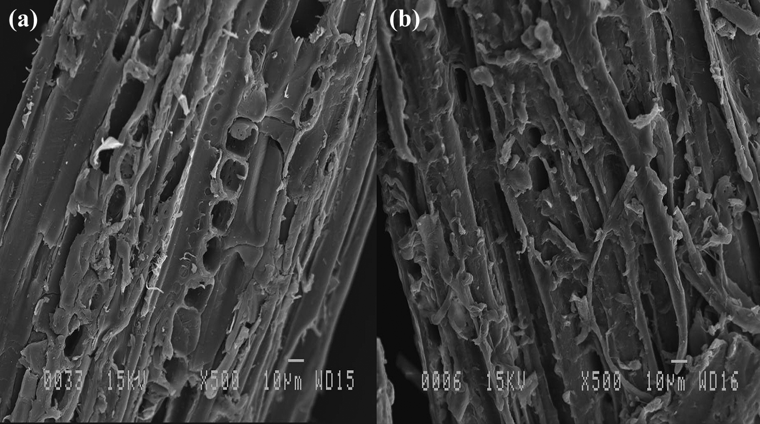
SEM images of (a) untreated and (b) treated maple fibers.
Density
Fibers’ density are reported in Table 2. It can be seen that on average, the density of the modified maple fibers is about 8% higher than their untreated counterparts. This can be explained by the extraction of some lignins and hemicelluloses during the solution treatment at high temperature as well as the effect of the MAPE layer coating the fibers. The MAPE molecules are expected to cover the fibers’ surface, thus increasing the weight and reducing porosity.
Density of the different fibers used.

UF: untreated fiber; TF: treated fiber.
SEM of the composites
Figure 2 presents typical SEM images of the 20% Figure 2(a), (c), and (e) and 30% untreated Figure 2(g), (l), and (k), as well as the 20% Figure 2(b), (d), and (f), and 30% Figure 2(h), (j), and (l) solution TFs. It can be seen that the composites based on neat maple (untreated composite small (UCS), untreated composite medium (UCM), and untreated composite large (UCL)) have a high amount of holes produced by fiber debonding (white circles). These holes are the result of fiber pull-out and are typical in composites with poor fiber wettability and adhesion. On the other hand, the composites based on treated maple (treated composite small (TCS), treated composite medium (TCM), and treated composite large (TCL)) show a more homogeneous morphology (more uniform texture) with less gaps and voids (white circles). This can be explained by better fiber dispersion/compatibility/wettability/adhesion due to the presence of the MAPE surface layer on the fiber’s surface as observed in Figure 1(b).

Typical SEM images of the untreated (a) UCS, (c) UCM, (e) UCL, (g) UCS, (i) UCM, and (k) UCL and treated (b) TCS, (d) TCM, (f) TCL, (h) TCS, (j) TCM, and (l) TCL maple fiber composites at 20% and 30%, respectively.
Composite density
Figure 3 presents the density of the composites as a function of particle size. The results show that the density increases with filler content due to the higher density of the wood fibers (1.4–1.6 g cm−3) compared to LLDPE (0.94 g cm−3). 23,24 On the other hand, the treated composites exhibit higher densities than untreated ones. This can be explained by the presence of more voids/gaps in UC (Figure 2) and the higher density of treated fiber (TF) (Table 2). These observations are in agreement with the findings of Kakroodi et al. 25 who reported that the addition of a coupling agent increased the composite density due to better interfacial contact between the fibers and the matrix. Furthermore, according to Ameh et al., 24 composite density increases with increasing particle size because smaller particles are expected to be more compressible since they have more porosity. 24 As seen in Table 2, a slight density increase of maple fibers with increasing particle size (with and without solution treatment) is also observed.

Composite density as a function of particle size and surface treatment.
Thermal stability of the composites
TGA was used to investigate the effect of maple fibers on the thermal stability of the composites. Figure 4(a) and (b) presents the TGA and DTG curves of neat LLDPE (30°C min−1) as well as UCL and TCL maple fiber composites at 20 wt% The composite curves show two degradation steps. The first one between 200°C and 350°C can be associated to the thermal degradation of maple fibers (T M), 26 with a maximum in the DTG curves around 359 and 360°C for the UCL and TCL composites, respectively. The second step between 350°C and 550°C is associated to the thermal decomposition of the polymer (T L) matrix, 14 with a maximum in the DTG curves at 471°C, 474°C, and 475°C for LLDPE, UCL, and TCL, respectively. The results show that an increase in T L peak by about 3 and 4°C for UCL and TCL, respectively, suggests a small thermal stability improvement imparted by the maple fibers compared to neat LLDPE. 14
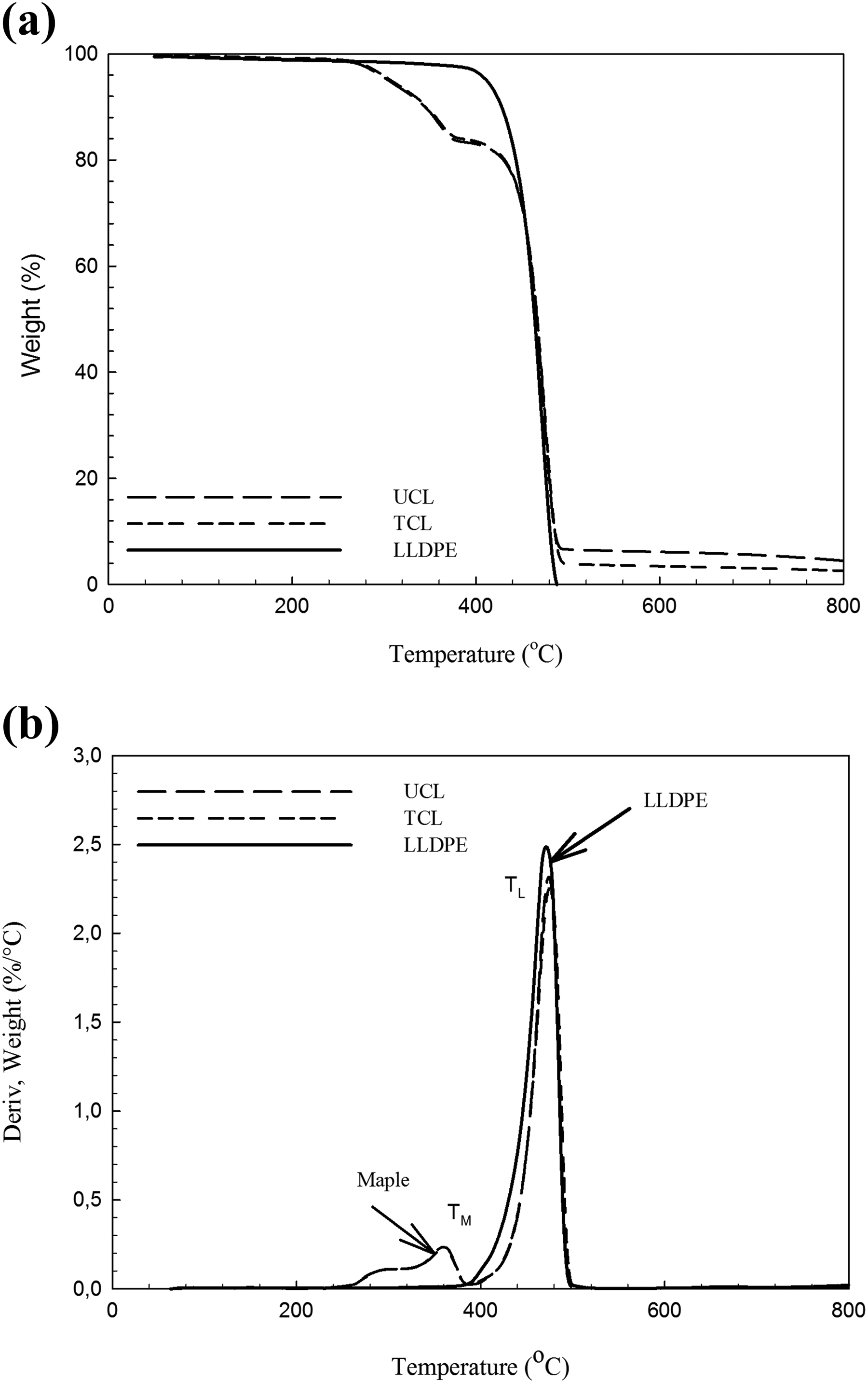
(a) TGA and (b) DTG curves of UCL and TCL composites, as well as the neat LLDPE (30°C min−1 under nitrogen atmosphere).
Table 3 shows that the degradation temperature of the LLDPE (T L) slightly increased with the introduction of maple for TCL composite (about 1.3, 3.7, and 2.9°C at 10, 20, and 30°C min−1, respectively). The same trend is observed for the maple phase degradation peak (T M). These observations again show that the maple modification was successful leading to improved thermal stability of the maple fibers because of better interfacial properties of the TFs. 27
Comparison between the thermal decomposition temperature (°C) of the materials at different heating rates under nitrogen atmosphere.

LLDPE: linear low-density polyethylene; UCL: untreated composite large; TCL: treated composite large.
Mechanical properties of the composites
To evaluate the combined effects of surface modification and wood fiber content, as well as particle size on the mechanical behavior of the composites, tensile, flexural, and impact tests were carried, and the results are discussed below.
Tensile properties
Figure 5 shows that in general, the tensile modulus increases with wood content, particle sizes, and surface treatment. The only exception is the 30% of the smallest particles (125–250 µm) probably because there is not enough polymer to cover all the surface area of the small particles, the absence of pressure to get good interfacial contact, and possible fiber agglomeration. 9,28,29

Tensile modulus as a function of particle size and surface treatment.
Higher modulus with wood addition is expected because the modulus of maple fibers (10–13 GPa) is higher than the neat LLDPE (174 MPa). 9,10 On the other hand, the treated maple fibers composites show significant improvement compared to untreated maple fibers. The best improvement is achieved at 20% wood (218 and 246 MPa) for TCS and TCM, respectively, and at 30 wt% (272 MPa) for TCL. This modulus increases for the treated maple fibers composites (TCS, TCM, and TCL) compared with their respective unmodified maple composites (UCS, UCM, and UCL) as also observed by Verdaguer and Rodrigue, 15 Raymond and Rodrigue, 16 and Farsi et al. 30 This is due to both the fiber treatment and the increased filler content which improved the adhesion and the stiffness. 31 Concerning the effect of particle sizes, Figure 5 shows that the modulus increases with the particle size for the higher filler content (30 wt%) composites; that is, about 7%, 40%, and 73% for TCS, TCM, and TCL, respectively, compared to neat LLDPE. These results are in good agreement with Bouafif et al. 32
Figure 6 presents the tensile strength of LLDPE and the composites. A decreasing trend is observed between neat LLDPE and the untreated fiber composites. For example, at 20% of untreated fibers (UCS, UCM, and UCL), the tensile strength decreased by about 35, 22%, and 28% respectively, compared to LLDPE. This is due to poor adhesion between the untreated fibers and LLDPE limiting interfacial stress transfer. 10 On the contrary, the tensile strength of the composites based on treated maple fibers increased, up to 20 wt% for TCS, TCM, and TCL (about 10%, 19%, and 7%, respectively). At higher fiber content (30 wt%) the tensile strength decreased and this is attributed to the high amount of fiber loading promoting agglomeration. But the tensile strength values for the treated composites are still higher than for untreated ones (about 143% and 114% for TCM and TCL compared to UCM and UCL, respectively). This improvement can be explained by the presence of a thin layer of coupling agent on the fibers’ surface (see Figure 2(b)) increasing their compatibility with the matrix and improving the interfacial adhesion leading to better stress transfer from the matrix to the fibers. 25 At high fiber content (30 wt%), tensile strength increases with particle size from TCS to TCL and a similar trend was reported by Kociszewski et al. 33

Tensile strength as a function of particle size and surface treatment.
Figure 7 shows that in general, the elongation at break of the composites is much lower than the neat matrix due to the addition of rigid (low elasticity) particles crating local defects in the polymer entanglement network. It can be seen that the elongation at break decreases with wood content, while some improvement is obtained with surface treatment. 14,15 For example, the presence of MAPE in TCS led to a 59% and 55% increase at 10 and 20 wt%, respectively. Finally, the effect of particle size was negligible for the range studied and similar trends were reported by Nourbakhsh and Ashori. 18

Tensile elongation at break as a function of particle size and surface treatment.
Flexural properties
Figure 8 shows that the flexural modulus results are similar as the tensile modulus results of Figure 5. The flexural modulus increased at lower fiber content (10 and 20 wt%) and the optimum flexural modulus was obtained at 20 wt% for UCS, UCM, and UCL (about 823, 815, and 867 MPa) respectively, compared to neat LLDPE (606 MPa). This improvement is again related to fiber stiffness compared to the neat matrix. 9 But, the values are even higher than the matrix for UCM and UCL at 30 wt%. Although the composites prepared from treated maple fibers show significant improvement, the best flexural modulus improvement was obtained for the TF composites at 20 wt% with 44%, 60%, and 50% increase for TCS, TCM, and TCL, respectively, with respect to the neat LLDPE. This increase can be attributed to good interfacial bonding allowing stress transfer from the matrix to the fibers. 34 Also, the flexural modulus was found to increase with increasing particle size from TCS to TCL. Similar results have been reported by Kociszewski et al. 33 and Li. 35 Finally, the lower values observed at 30% can be associated to defects (particle-particle contact) limiting stress transfer.

Flexural modulus as a function of particle size and surface treatment.
Impact properties
Figure 9 presents the Charpy impact strength results. As expected, the impact strength decreases with fiber loading. 10 This is due to the addition of rigid particles (low elasticity) and higher probability of fiber–fiber interaction (contact) and fiber ends promoting defects and facilitating crack initiation and propagation. 36,37 Nevertheless, the impact strength of the TFs are slightly higher than for untreated ones because a better interface was produced between the maple fibers and the LLDPE; that is, lower amount of voids and defects. The impact strength was also found to increase with increasing particle size from TCS to TCL. 38 The impact strength of TCL is on average 24%, 15%, and 52% higher than for TCS at 10, 20 and 30 wt%, respectively. According to Kociszewski et al., 33 one important factor affecting the mechanical properties is the fiber aspect ratio L/D. Fibers with a higher aspect ratio have higher stress transfer capacity from the polymer matrix to the fibers and to improve the composites properties. 33 Also, longer fibers need more energy before their complete extraction (pull-out) from the matrix. This is also improved when better interfacial stress transfer occurs with surface TFs.
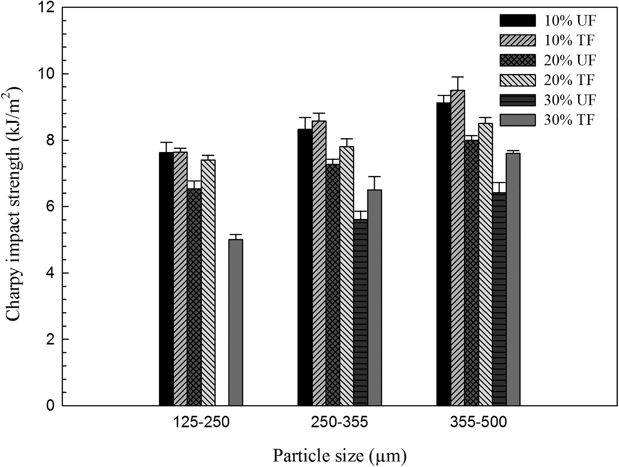
Charpy impact strength as a function of particle size and surface.
Conclusion
In this study, the effects of fiber surface treatment, concentration and size on the mechanical properties of LLDPE-based composites have been investigated. In particular, the simple dry blending technique was used to limit material degradation and have a faster process, especially when rotomolding is used under optimized conditions.
The results showed that the addition of a coupling agent increased the LLDPE/maple interface quality which also improved both the density and thermal stability of the molded parts. But the main effect of surface treatment was to improve the mechanical properties of the matrix: 56% (TCL at 30 wt%) for the tensile modulus and 50% (TCL at 20 wt%) for the flexural modulus. The effect of particle size was also significant. For example, at 30 wt% of modified maple fibers, the tensile strength was improved by 114% when the particle size increased from TCS to TCL. At the same loading (30 wt%), the tensile modulus also increased with particle size by 7%, 40%, and 73% for TCS, TCM, and TCL, respectively, compared to neat LLDPE. Finally, the impact strength was also modified with TCL being 52% higher than TCS at 30 wt%
Footnotes
Acknowledgements
The authors would like to thank the Research Center for High Performance Polymer and Composite Systems (CREPEC), Centre de Recherches sur les Matériaux Avancés (CERMA), and Centre de Recherche sur les Matériaux Renouvelables (CRMR) of Université Laval for financial and technical support. The technical help of Yann Giroux was also very much appreciated.
Declaration of conflicting interests
The author(s) declare no potential conflicts of interest with respect to the research, authorship, and/or publication of this article.
Funding
The author(s) disclosed receipt of the following financial support for the research, authorship, and/or publication of this article: This work was supported by the Natural Sciences and Engineering Research Council of Canada (NSERC).