
Abstract
In this study, wood-plastic composites (WPC) were produced by rotomoulding, to study the effect of fibre content and surface treatment on their properties. Maple wood fibre, with or without surface treatment with maleated polyethylene (MAPE), was used to improve the mechanical properties of linear low-density polyethylene (LLDPE). From the composites produced, a complete morphological and mechanical characterisation was performed. The results showed that MAPE surface treatment improved the fibre-matrix interface quality and the mechanical properties (56% increase in tensile modulus and 60% increase in flexural modulus over the neat matrix with 19% in impact strength with respect to untreated fibres) at 30% wt.
Introduction
Rotational moulding, also known as rotomoulding or rotocasting, is a manufacturing process having virtually unlimited design possibility to produce complex shapes over a wide range of sizes. But the main advantage of rotomoulding is the possibility to produce hollow parts without weld-lines which are always weak points, especially for polymer composites. Compared to other plastic moulding processes like injection moulding, rotational moulding benefits from low-cost moulds (material and thickness) since no pressure is applied on the materials leading to stress-free parts. The thickness of the final part is directly related to the amount of material loaded, as well as the biaxial rotational speed and mould thickness. Nevertheless, rotational moulding also has some disadvantages, the main ones being long cycle times and the limited range of materials to select from1–3.
The rotational moulding cycle can be decomposed into four stages. Firstly, the mould is charged with a predetermined amount of materials (powders, micro-pellets or viscous liquids). Then, the mould is closed, starts to rotate about two perpendicular axes where the velocity in each direction (speed ratio) is carefully controlled, and placed inside a heated oven. Once the material has fully melted and sintered (heating step), the mould is moved to a cooling stage using air (forced convection), water mist or a combination of both. When the material can be handled, the product is demoulded and a new cycle begins 4 .
Nowadays, the main rotational moulding applications are automotive (ducting, fuel tanks, etc.), marine industry (kayaks, dock floats, etc.), containers (tanks, reservoirs), and general industrial products (tool boxes, containers, toys, etc.) 4 . Polyvinyl chloride (PVC) was the first polymer introduced for different articles like toys and car interiors (door panels, dash-boards). In the late 1950s, polyethylene powder became available for rotational moulding applications. Today, the different grades of polyethylene (LLDPE, LMDPE, LDPE, HDPE, MDPE, etc.) represent close to 90% of all the polymers rotationally moulded4–6. Recently, there has been increasing interest in the rotational moulding of composite parts to reduce costs (using low cost fillers) and/or improve mechanical properties. Over the last years, the average sales of the North American rotomoulding business sustained an annual growth rate of 7.2% between 2009 and 2014 7 . A similar trend was observed for composite materials as the total sales of the North American production was about $7.4 billion in 2013 and is expected to increase to $11.3 billion by 2019 8 . For these materials, their main applications are in transportation, civil infrastructure, sporting goods, packaging, as well as different commercial and engineering applications 8 . One reason for the growing commercial production of polymer composites is the interest being given to natural fibres (lignocellulosic) because they are ecologically and toxicologically harmless, biodegradable, CO2 neutral, low cost and lightweight9–11.
To rotomould a composite part based on a thermoplastic matrix and a reinforcing particle, two techniques can be used. The first method is to produce a compound via melt blending (batch mixer, twin-screw extrusion, etc.), then to pelletise/pulverise the materials. Good adhesion (especially if coupling agents are added) and dispersion of the solid particles is expected by this technique, but thermo-oxidative and mechanical degradation of the materials (matrix and reinforcement) is expected in every processing step. To overcome some of these problems, a second methodology was developed more recently: dry-blending. As all the initial materials are in a powder form, high-shear mixers can be used to disperse the materials before being loaded in the mould. This method has several benefits as being fast, low cost and very limited material degradation occurs 12 . Nevertheless, this method has some limitations, the main one being the poor adhesion (interfacial voids) at the particle-matrix interface due to the lack of compatibility and the absence of pressure to compact the materials. This led to low mechanical properties of the final product. Fortunately, this problem can be solved by performing a surface treatment on the particles as the interface between the fibres and the matrix is controlling the mechanical properties of composites. Poor adhesion results in low interfacial interaction limiting load transfer and leading to composites having low mechanical properties 13 . But the polar and hydrophilic natural fibres are incompatible with most polymers which are non-polar and hydrophobic. This incompatibility leads to poor interface quality and poor mechanical performances10–14. But good interfacial adhesion (compatibility) between natural fibres and polymer matrices can be achieved by using physical or chemical surface treatments13–15. This can also lead to other advantages like improved mechanical properties, moisture resistance and better fibres distribution allowing the possibility to use higher fibre contents in rotational moulding9–16. To this purpose, maleated copolymers (coupling agents) were developed as these molecules provide efficient interaction with the functional surface of the fibres and the matrix. A similar study was done by Gupta et al. 17 and their results showed a significant modulus improvement which was attributed to polymer chains orientation during the biaxial orientation process. On the other hand, the elongation at break and fracture (break) stress decreased with up to 10% vol. of phosphate glass (P glass) in the composites as compared to neat poly(propylene-graft-maleic anhydride) (PPgMA). They also reported compatibility improvement as a result of maleated polypropylene being used as a reactive compatibiliser for polypropylene/inorganic glass composites. Gupta et al. 18 studied the structure and gas barrier properties of PPgMA/P glass composites prepared by microlayer co-extrusion. They reported that better interfacial compatibility was the result of hydrogen bonding between the hydroxyl groups on the glass surface and the maleic anhydride group in PPgMA. This effect led to improved interfacial adhesion with well dispersed fillers when PPgMA was used as the polymer matrix 18 . Another example is maleated polyethylene (MAPE) where the maleic anhydride groups of MAPE can react with the hydroxyl groups (OH) of the amorphous region of cellulose, while physical entanglement can be obtained between the polyethylene molecules of the matrix and the PE part of MAPE. These interaction/reaction mechanisms were described in details elsewhere19,20. Unfortunately, when a coupling agent is directly mixed with a polymer/fibre compound via melt blending, dispersion is not always guaranteed; so the best method to avoid this limitation, especially when using dry-blending, is to perform the fibre surface modification before their introduction in the matrix. This method can be done in solution and was successfully performed on maple and hemp by Cisneros-López et al. 16 , Chimeni et al. 19 , Verdaguer and Rodrigue 21 , and Raymond and Rodrigue 22 .
Based on the recent developments in rotomoulded composites, fibre surface treatment and dry-blending processing, the main objective of this work is to study the effect of fibre surface treatment (MAPE in solution) and concentration (10, 20 and 30%) on the morphological and mechanical properties of maple wood fibre/polyethylene composites.
Experimental
Materials
The polymer used was linear low-density polyethylene (LLDPE) powder (EXXON MOBIL LL 8555). The density of LLDPE is 936 kg/m3 with a melting temperature and melt flow index (MFI) of 126°C and 6.8 g/10 min (190°C/2.16 kg), respectively. The solvent used for wood fibre surface treatment was xylene (laboratory purity grade) from Fisher Chemicals (USA) and the coupling agent was maleic anhydride grafted polyethylene (MAPE): Epolene C26 (Westlake Chemicals, USA). The latter has an average molecular mass of 65 kg/mol, a MFI of 8.0 g/10 min (190°C/2.16 kg), an acid number of 8.0 mg KOH/g and a melting point of 121°C. As reinforcement, maple wood fibre was purchased from PWI Industries (Canada). The particles were sieved to keep only particles between 355 and 500 μm. This represents about the same range as the LLDPE powder to improve dry-blending and limit particle segregation.
Wood surface treatment
Wood surface treatment was performed as reported by Verdaguer and Rodrigue 21 . A solution of 1% MAPE in xylene was prepared at 80–90°C. Then, the wood particles were added and left for 30 min in the solution under high intensity mixing. A solid:solution (maple:xylene) ratio of 1:10 (w/v) was used 22 . Finally the treated wood particles were filtered and dried overnight at 60°C in an oven.
Sample production
The samples were produced using the following steps. Firstly, maple and LLDPE were dry-blended with a high shear mixer Skyfood LAR-15LMB (Skyfood, USA) at 3320 rpm for 4–5 min to get a homogeneous blend. Then, around 700 g of the powder blend was placed in an aluminium mould having a cubic shape (20 × 20 × 20 cm3) which was used to produce the rotationally moulded parts with an approximate wall thickness of 9.5 mm (3/8”) for the lateral and 12.7 mm (1/2”) for the top/bottom sides. Before loading, a demoulding agent (Trasys 420) was applied inside the mould. The charged mould was then closed and introduced into the oven which was previously heated at 280°C. Subsequently the mould was kept rotating for 20 min at a rotational speed ratio of 4:1, followed by a cooling period of 38 min with forced air (blowing fan).
Characterisations
Fourier transform infrared spectroscopy (FTIR)
Infrared spectra were obtained with a Nicolet FTIR spectrometer model 730 (Nicolet Instruments, USA) equipped with a mercury-cadmium-telluride detector. The absorbance was measured in the 4000–750 cm−1 region. Each spectrum was obtained from 128 scans at a resolution of 4 cm−1.
Thermogravimetric analysis (TGA)
The maple fibres (untreated and treated) were subjected to thermogravimetric analysis using a Q5000IR (TA Instruments, USA). Samples between 5 and 10 mg were analysed by heating up at 10°C/min from 50 to 700°C in a nitrogen atmosphere.
Morphology
For the morphological characterisation, a scanning electron microscope (SEM) JEOL JSM-840 was used. The moulded samples were first frozen in liquid nitrogen and then broken to be coated with Pd/Au prior to observation and images were taken at different magnifications.
Density
Density was obtained by a gas pycnometer ULTRAPYC 1200e (Quantachrome Instruments, USA) using nitrogen as the gas phase. The data reported are the average of five measurements while standard deviations were less than 1%.
Tension test
Young's modulus, tensile strength and elongation at break were measured using an Instron model 5565 universal testing machine (Instron, USA) with a 500 N load cell. Type V dog bones were cut from the moulded parts according to ASTM D638. The crosshead speed was set at 10 mm/min and the tests were performed at room temperature. Five samples were tested to report on the average and standard deviation.
Flexion test
Flexural tests were performed at room temperature using a crosshead speed of 2 mm/min on an Instron universal tester model 5565 (Instron, USA) with a 50 N load cell according to ASTM D790. Sample dimensions were 125 × 12.7 × 3 mm3 and the span length was fixed at 60 mm. At least five samples were used to report the average and standard deviation.
Impact test
Charpy impact strength test was done on a Tinius Olsen testing machine model
Impact 104 (Tinius Olsen, USA) operating with a pendulum weight of 0.242 kg
(1.22 J). The arm length was 279 mm, leading to an impact speed of 3.3
ms−1. Rectangular samples with “V” notch produced by an
automatic sample notcher model ASN (Dynisco, USA), at least 24 h before
testing, were performed at room temperature and the results are the average
of ten repetitions. For all the samples produced,
Codes used for the samples produced

Codes used for the samples produced
Confirmation of maple surface modification
FTIR, TGA, density and SEM tests were used to determine the level of surface modification on the maple fibres after solution treatment.
Fourier transform infrared (FTIR) spectroscopic analysis
The FTIR spectra of MAPE, untreated and treated maple fibres are shown in

FTIR spectra for MAPE, UF and TF maple fibres
Thermogravimetry was used to determine if MAPE was present on the fibre's
surface. The corresponding TGA and DTG curves of untreated (UF) and MAPE
solution treated (TF) maple fibres, as well as MAPE are presented in


Thermogravimetric results: (a) TGA and (b) DTG curves
Using the experimental values, TGR = 22%.
To get more information about maple surface modification by MAPE in solution,
the density of the fibres was measured and the results are presented in
Density of the different raw materials used

Density of the different raw materials used
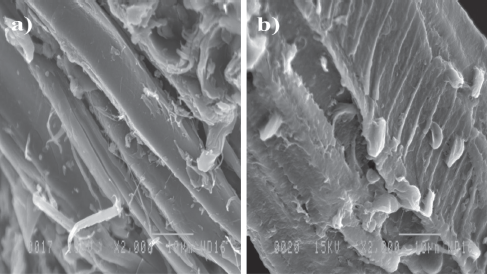
SEM images of: (a) untreated and (b) treated maple fibres
So, based on the characterisations made, it can be concluded that MAPE was successfully grafted onto the surface of the maple fibres.

Typical SEM images of untreated (a: 10%, c: 20% and e: 30%) and treated (b: 10%, d: 20% and f: 30%) maple fibre composites
LLDPE density as a function of TF and UF content
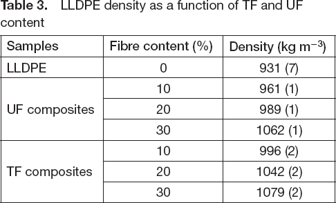
LLDPE density as a function of TF and UF content
Tensile properties

Tensile modulus as a function of UF and TF content

Tensile strength as a function of UF and TF content

Tensile elongation at break as a function of UF and TF content

Flexural modulus as a function of UF and TF content
The Charpy impact strength results are presented in

Charpy impact strength as a function of UF and TF content
This work investigated the effect of fibre surface modification (MAPE in solution) and fibre content (0–30% wt.) on the morphological and mechanical properties of maple/LLDPE composites produced by rotational moulding. From the samples produced, several conclusions can be made:
FTIR, SEM, density and TGA results showed that the surface modification in solution was successful and a thin MAPE (coupling agent) layer on the fibre surface was obtained. It is estimated that about 22% MAPE was grafted.
The morphological analysis of the composites showed that more homogeneous samples were produced with treated fibres, due to better interfacial contact and less defects compared to untreated maple. This led to higher composite density.
Finally, the mechanical properties (tensile modulus, tensile strength, flexural modulus and impact strength) of the composites based on treated maple fibres were all significantly improved. For example, tensile modulus (56%) and strength (10%) were increased at 30% and 20%, respectively for TF. On the other hand, elongation at break always decreased with both UF and TF.
Nevertheless, more work needs to be done to determine the optimum fibre content for a specific application.
Footnotes
Acknowledgement
The authors would like to thank the financial support of the Natural Sciences and Engineering Research Council of Canada (NSERC), the Research Center for high performance polymer and composite systems (CREPEC), as well as Centre de Recherches sur les Matέriaux Avancέs (CERMA) and Centre de Recherche sur les Matέriaux Renouvelables (CRMR) of Universitέ Laval for financial and technical support. The technical help of Mr. Yann Giroux was also much appreciated.