
Abstract
In this study, quasi-static punch shear behavior of aramid epoxy composites was investigated both numerically and experimentally. Firstly, material model parameters used in numerical simulations were obtained by various mechanical tests such as tensile, compression, and in-plane shear tests. Different damage mechanisms that were observed during each test were the focus of interest. Then quasi-static punch shear test was performed and verified with numerical simulations. After the verification of material model, punch tests, which have different boundary conditions, were run numerically, and the effect of thickness and span-to-punch ratio (SPR) were determined for aramid/epoxy composites. It is concluded that failure mechanisms of composite samples were related to SPR. When SPR increases, the failure mode was shifted from shear-dominated failure to bending-dominated failure behavior. Additionally, punch shear strength value at minimum SPR (1.1) was eight times bigger than the value at maximum one (8).
Introduction
Polymer matrix composites have been extensively used in a wide range of applications such as aerospace, automotive, marine, and defense industries on account of their high stiffness and strength to weight ratio, low density, and impact resistance. 1 -3 They have flexibility in design by way of fiber orientation, variations of hybridization, and stacking sequence. Especially high strength to weight ratio and flexibility in design are crucial material properties in impact loading applications. They can also absorb the impact energy through different damage mechanisms, such as delamination, 4 matrix cracking, 5 and fiber breakage, and have great importance in the field of energy absorption applications. Generally, these mechanisms are formed under dynamic loadings such as low 3,6 -11 and high velocity impacts. 12 -17 The main problem in preventing impact damage is the involvement of various parameters in an impact and the sudden occurrence of induced damage. If the damage mechanism of composite materials is well understood, it would be possible to eliminate the effect of impact loadings. Recently, Gama and Gillespie have developed an important methodology, namely quasi-static punch shear test (QS-PST) to understand ballistic damage. 18 By applying this method, the ballistic damage mechanism phases including (i) impact contact and stress wave propagation, (ii) hydrostatic compression and local punch shear, (iii) shear plug formation under compression–shear, (iv) large deformation under tension–shear, and (v) end of penetration and structural vibration can be understood. Additionally, different parameters of QS-PST for various composites such as carbon fiber, glass fiber, and GLARE (glass laminate aluminum-reinforced epoxy) have been studied in the literature. 19 -23
For example, Jordan et al. 24 performed a number of dynamic tests such as low-velocity and ballistic impact to obtain material model and determined the response of E-glass/phenolic composites under dynamic loading. The QS-PSTs, which have different span-to-punch ratios (SPRs) (1.020, 1.037, 1.053, and 1.171), were tested to plot load–displacement curves. According to the results, the maximum load values were distinctly decreased by increasing SPR. In another study, Erkendirci and Haque performed the QS-PST at different SPRs including 1.16, 1.33, 1.67, 2.00, 2.33, and 2.67 with plain weave Kevlar/high-density polyethylene (HDPE) composites having different thickness. 25 Due to the viscoelastic–plastic behavior of HDPE, these composites exhibited efficient performance to the dissipate impact energy.
On the other hand, numerical simulations are important to predict physical phenomena such as crash, impact, drop, and crush events. For a proper analysis, many material properties must be supplied to simulate composite material behaviors under different loading. Jordan et al. 24 obtained MAT162 material model parameters of plain weave E-glass/phenolic resin composite. In the study, they used low-velocity impact (LVI), depth of penetration (DoP), and ballistic tests to obtain material model parameters with respect to damage mechanism.
In the present work, the quasi-static penetration behavior of aramid/epoxy composites was investigated by QS-PST. To the best of our knowledge, this behavior of aramid/epoxy composites has not been studied previously by numerical and experimental studies. To achieve the purpose, punch tests having different SPRs (1.1, 2, 4, and 8) were simulated and force–deflection curves were obtained. Thus, the influence of thickness and SPR on punch shear strength (PSS) were clearly determined for aramid/epoxy composites, which are generally utilized in ballistic applications. The material model parameters will be varied for epoxy composite reinforced by other fibers such as glass, carbon, and ultrahigh-molecular-weight polyethylene in further studies.
Materials and methods
Twaron CT-709 plain weave fabric having an areal density of 200 g/m2, Araldite LY1564 epoxy resin, and Aradur 3487 amine-based hardener were used as fiber and matrix materials, respectively. Amount of hardener used per 100 g of epoxy resin was calculated as 34 g. All samples were manufactured with 12 layers of fabric by vacuum-assisted resin transfer molding (VARTM) method to obtain 3 mm of thickness as seen in Figure 1. First, aluminum plate was heated to 100°C in 20 min. Then, epoxy resin mixture was transferred through the aramid fabrics and kept under 100°C for 1 h and cooled to the room temperature for 24 h. Fiber weight fraction of composites was determined as 65% at the end of manufacturing process.

VARTM process and equipment (left), Test samples (Right).
Tensile, compression, and shear tests were executed to obtain material model for aramid–epoxy composite material. Test samples were cut via CNC water jet machine (manufactured by CT Cutting Technologies & Machinery LLC.) from one large plate to provide stability among all samples.
Experimental study
All mechanical tests were performed by using a Shimadzu AGSX series universal electromechanical test device manufactured by Shimadzu Scientific Instruments which has a load cell of 50 kN. Tensile, compression and in-plane shear tests were conducted according to ASTM D3039, ASTM D6641, and ASTM D7078 standards, respectively. Tensile and shear test speeds were 2 mm/min and compression test speed was 1.3 mm/min as stated in ASTM standards. Gage length of samples was determined as 13 mm to avoid from buckling during the compression. Special test fixtures were manufactured for shear, compression, and punch tests. All mechanical tests applied to composite samples were presented in Figure 2.

Mechanical tests applied to composite samples (a) Tensile (b) In-plane shear (c) Quasi-static punch shear (d) Compression.
Although different types of shear tests for composites have existed such as short-beam shear, two-rail shear, three-rail shear, and ±45° tensile shear, the V-notched rail shear test was chosen due to appliance of a uniform shear stress was applied to the test sample. Bolts of the shear test apparatus were tightened of 55 Nm of torque. Less torque may cause slipping the sample between grips.
QS-PST was applied to the composite plate to determine quasi-static penetration resistance of the material. All QS-PST were performed in Shimadzu AGSX which has a load cell of 100 kN. The general schematic drawing of QS-PST apparatus was obtained according to the literature, 26 as shown in Figure 3. The H c is the thickness of sample, while D p and D s are diameters of punch and span, respectively. There were two main test parameters in QS-PST which thickness of sample (H c) and SPR (D s/D p). SPR was kept constant as 2 through this study. Test speed was chosen as 2.54 mm/min in all tests. 18,26,27

Schematic drawing of quasi static punch shear test.
Numerical study
There are different material models to modelling composites in Ls-Dyna material library such as Mat 22, 54–55, 58–59, and 161–162. Some of these models need extra material properties for modelling failure, delamination, or post-damage effects. Mat 54 (Mat_Enhanced_Composite_Damage) and Mat 20 (Mat_Rigid) material models were used for composite and punch, respectively. Constitutive equations related to numerical simulations given as follows:


where α is nonlinear shear stress parameter which can be calibrated by trial and error if shear is exist.
Additionally, Chang/Chang failure criteria used in Mat 54 material model was given as follows for the tensile fiber mode (equation (4)), where


Mat 54 material model contains two strength reduction parameters named as FBRT and YCFAC, which are used to degrade initial fiber strength. This reduced fiber strength can be calculated such as equations (8) and (9) as follows:


The LS-PrePost 4.3 preprocessor software was also used to prepare Ls-Dyna keyword file including problem definition, boundary conditions, and material models, then this keyword file was run in Ls-Dyna solver.
Figure 4 represents to SPR concept used in numerical simulations. Nodes in the white areas were fixed in all directions, while the others were free to rotation and displacement. In total, 90,000 shell elements were used in the composite plate. Same numbers of elements were used in all simulations to avoid numerical instabilities in simulations that have high SPR.

Span to punch ratio concept used in numerical studies. White areas imply to fixed nodes.
Integration points and lay-up properties were defined by INTEGRATION_SHELL and SECTION_SHELL keywords, respectively. Automatic surface-to-surface contact modelling was generated to provide contact between punch and composite plate. Table 1 presents material properties obtained from mechanical tests. Longitudinal and transverse properties were assumed as equal due to the nature of plain weave [0/90] fabric structure.
Material properties of aramid epoxy composite used in numerical study.

Results and discussion
Tensile, compression, and in-plane shear test results
Several tests such as tensile, compression, and in-plane shear were performed to determine the mechanical properties of aramid/epoxy composite containing 65% fiber ratio by weight (Figure 5). In the case of the tensile test, the sample failed at 49.3 kN of force and 6.8% of strain. However, the maximum compression strength was determined as 110 MPa, and it failed at 7.38% of strain. Additionally, the maximum shear stress was observed at 125 MPa at the strain of 65%. Notably, the composite sample exhibited a linear behavior until the first damage mechanism started at 5% of strain. The load drop noticed at 65% of strain and the test was terminated at this point.

Experimental results of mechanical tests of composite samples.
In the cases of compression and shear tests, both composite samples displayed failure mechanisms, which are represented in Figure 6(a) and (b), respectively. Kink band formations were observed at the edge of compression test. This failure was reasonable according to the relevant compression test standard. On the other hand, the fiber–matrix debonding was occurred when it was reached to maximum force during the shear test.

Tested samples. (a) In-plane shear (b) Compression (c) Top and side views of tensile test sample.
At the end of tensile test, the failure mode resulting from edge delamination at the middle of gage area was observed (Figure 6(c)). The main reason of this damage mechanism might be primarily a result of poor interphase interactions between fiber and matrix as the loading increases. Additionally, this tensile test sample exhibited a linearly elastic behavior until the maximum loading.
QS-PST results
To recognize quasi-static penetration behavior of the composite samples, the QS-PST was applied and the result was indicated in Figure 7. The delamination area, which was marked by black borders, was visually observed under light. It was remarkably noticed that this marked area was larger than the surface area of the punch. This result might be originated from the dissipation of energy through thickness direction.

Samples the end of punch tests. (a) bottom view (b) top view and delamination areas.
Top and bottom views of tested area were examined under the optical microscope for better understanding of damage types (Figure 8). After optical microscope investigation, the damage mechanisms such as delamination, fiber pull out, fiber splitting, and matrix cracking were clearly observed. The type of damage was changed from top to bottom layers by loading direction. The applied force was encountered by compression on the top layers and by tension on the bottom layers. Therefore, the fiber splitting has initially started at the bottom layers. The surface of the damaged plate was identified by an optical microscope, and three-dimensional color map of the sample was represented in the right corner of Figure 8. Based on the color map investigation, the blue color implied to the most deflected area of the damaged plate.
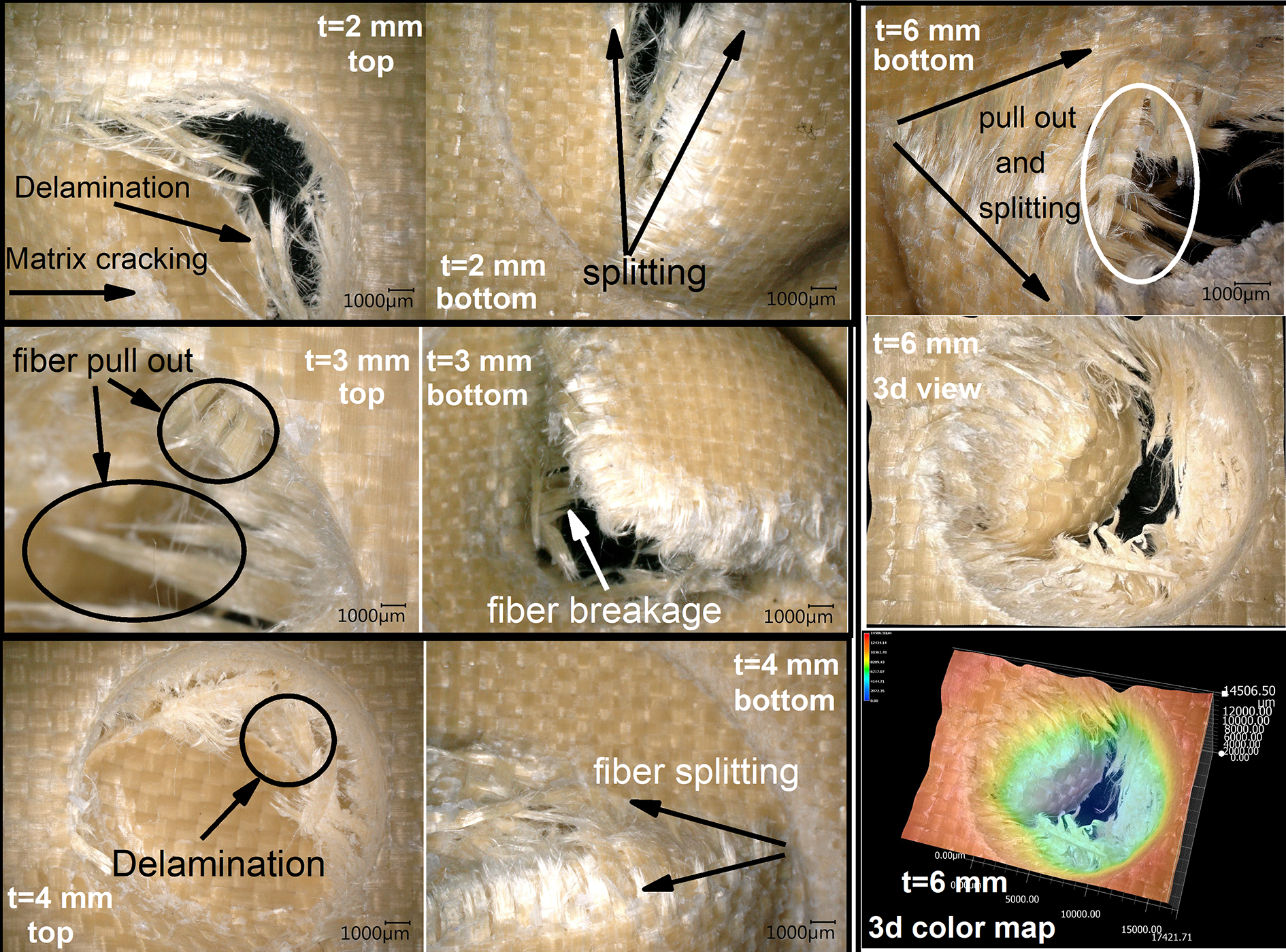
Optical microscope images of damaged samples and its failure mechanisms.
The PST behavior of samples having different thicknesses from 2 mm to 6 mm was determined. The curves displayed changes of contact force–deflection relationship between the composite plate and the punch (Figure 9). The damage process occurred into three stages 26 : (i) progressive damage zone, (ii) punch shear zone, and (iii) frictional sliding zone. As expected, the damage initiation force has linearly shifted from 3.24 kN to 6.56 kN by increasing thickness. Based on Figure 9, all samples exhibited similar trends where the matrix cracking was observed at damage initiation point. Then, the rigidity of the composite structure increases until the force reaches maximum point. Finally, fiber’s breakage has occurred before the load drop. This could be caused due to little oscillations at the end of progressive damage zone.

Force-Deflection curves of QS-PST of samples having different thicknesses.
After the progressive damage has completed, the punch shear zone was started during the tests. The contact force was constant or slightly decreased because damaged fiber carried the load for a while at this zone. In the final stage of the test called as frictional sliding zone, the punch and sample showed a frictional move with negligible resistance. On the other hand, an increase in the stiffness at the initial stage was also associated with an increase of thickness.
PSS was calculated by dividing the maximum force and shear area. 29

where D m was the mean diameter and was obtained by equation (11), and H c was the laminate thickness.

where D p was the punch diameter and D s was the span diameter. PSS of test samples is presented in Table 2.
PSS values of samples.

PSS: punch shear strength.
Numerical simulation results of QS-PST with different SPR and thicknesses
The simulation and experimental data were compared with different thicknesses (Figure 10). In all cases, similar trends were observed for damage processes at the initial stage. However, there was a slight difference by means of maximum contact force between simulation and experimental data of the sample having 2 mm thickness. This could be aroused from shell element formulation. It was remarkably noted that the numerical and experimental results were closer to each other as the thickness increases from 2 mm to 4 mm.

Comparison of numerical and experimental studies at different thicknesses.
Various boundary conditions were studied by numerical simulations with different SPR values including 1.1, 2, 4, and 8 (Figure 11). By increasing SPR, the load curves were clearly broadened for all thickness. This could be explained that the applied load by the punch subjected to more distributed area on the plate. The numerical results were checked with Gama and Gillespie’s study 18 in which performed QS-PST experiments with different SPR (1.1, 2, and 8). Our load curves obtained from numerical simulations were in good agreement with this study.

Numerical results of QS-PST for different thicknesses at different SPR.
The relationship between PSS and SPR was inversely proportional as clearly seen in Figure 12. In the case of sample with 3 mm thickness, the PSS values were recorded as 265.36 and 32.15 MPa for minimum (1.1) and maximum SPR (8) ratios, respectively. This could be explained by the influence of strength of fibers, which was more perceivable when SPR was getting smaller. Consequently, the boundary condition in QS-PST was directly related to damage modes of the composites.

PSS and SPR relationship obtained from numerical studies for different thicknesses.
Conclusions
Quasi-static penetration behavior of aramid/epoxy composites having different thicknesses ranging from 2 mm to 6 mm was investigated by both numerical and experimental analyses. Various mechanical tests including tensile, compression, and in-plane shear tests were performed to obtain material model parameters that used in numerical simulations. In the case of the mechanical tests, the maximum tensile and compression and shear strength values were determined as 577, 110, and 125 MPa, respectively. Since the simulation data were compatible with experiments, the numerical simulation could be applied for various samples having different SPRs that were not tested before. Conclusions obtained from this study could be summarized as follows: The maximum contact force was always occurred at the lowest SPR, while the most deflection was observed at the highest SPR. Also, when SPR increases, the failure mode was shifted from shear-dominated failure to bending-dominated failure behavior. Fiber splitting was observed as dominant damage mechanism at the end of QS-PST of aramid/epoxy composite samples having different thicknesses. PSS values were inversely proportional with SPR value. According to the numerical results, PSS values at SPR = 1.1 was eight times bigger than the values at SPR = 8. Present material model may be developed to perform LVI, ballistic impact, and DoP tests. In addition, several set of simulations will be run to calibrate the material model with experimental data. Most of the Mat162 progressive damage material model parameters can be obtained by this way as a further study.
Footnotes
Acknowledgements
Authors are grateful to Teijin Limited for supplying Twaron fabric. We would like to thank Cenk Kurtuluş and Mustafa Kuyumcu for their assistance in the manufacturing of composite samples.
Declaration of conflicting interests
The author(s) declared no potential conflicts of interest with respect to the research, authorship, and/or publication of this article.
Funding
The author(s) disclosed receipt of the following financial support for the research, authorship, and/or publication of this article: This study is supported by Marmara University, Scientific Research Projects Committee (BAPKO) with project number FEN-C-DRP-200716-0381.