
Abstract
The article presents an experimental investigation of anisotropic viscoelastic properties of a glass fiber-reinforced polymeric composite material. The experimental rig consisting of mechanical and heating parts was prepared for running the tests at room and elevated temperatures. Composite specimens, cut in three different directions, enabled evaluating three independent viscoelastic technical parameters. The stress–strain curves obtained at room temperature allowed to derive the elastic–plastic properties of the composite. It was found that the viscoelastic properties were not observed for room temperature, while an increase of the temperature up to 100°C shortens the relaxation time for less than 1 h. The creep curves, determined for the elevated temperature and different values of loads, demonstrate a good consistency for each type of specimens. In addition, strains are directly proportional to stresses for every time moment, which shows an evidence of linear viscoelastic properties of the composite material. A comparison of the creep curves proved an anisotropy of composite’s viscoelastic properties. Approximation of them by exponential Prony series makes the evaluated data applicable to the existing viscoelastic material models.
Introduction
Advanced composite materials are becoming more common due to their low weight and high mechanical properties. In particular, fiber-reinforced composites with polymeric matrix are widely used for engineering purposes. Glass fiber and carbon fiber-reinforced polymeric (GFRP and CFRP) composites find applications in a power industry (blades of steam and wind turbines, impeller elements), gas and oil transition systems (repair bandages of pipelines), aerospace industry (sheathing of spacecraft, fan stages of turbojet engines), civil industry (yacht hulls, fans, computer boards), and so on.
The composite materials are widely used in highly loaded elements of constructions and machines, and consequently, their strength should be investigated deeply and mechanical properties need to be evaluated. There are two principal approaches to the identification of composite properties. 1,2
The first approach is called structural approach and consists of analytical and numerical modeling of laminated structure and micromechanics of composites with fibers or layers of different properties.
Different properties of composite materials including their elasticity, viscoelasticity, creep, fracture toughness, and effects, including an influence of concentration ratio and a shape of inclusions, their diffusion, were investigated using this method. 3 -12
The second approach is called phenomenological approach and consists of series of experiments on specimens made of a composite material. A lot of mechanical properties of composite materials were identified using different experimental rigs and methods.
Elastic composite properties and rupture strength were considered in the study by Zak et al. 13 for Young’s modulus of short fiber-layered composites, 14 for dynamic elastic properties of concrete composites, 15 for shear properties of a composite laminate, 16 for mechanical properties of unidirectional steel fiber/polyester composites, 17 for orthotropic elastic properties and damage mechanics of woven composites, 18 for three-dimensional orthogonal bending properties of a honeycomb sandwich structure composite, 19 and for the fatigue life and damage parameters of a glass–epoxy composite.
The experimental investigation of quasi-static viscoelastic properties was performed in the study by Abot et al. 20 for in-plane loads of a satin fabric carbon/epoxy composite, 21 for interlaminar shear modulus of laminated composites, 22 for Prony series moduli and relaxation times as well as temperature shift functions of epoxy compounds, 23 for creep properties of an epoxy adhesive, 10 for the in-plane orthotropic viscoelastic properties of a glass fabric composite at elevated temperatures, 24 for compression viscoelastic parameters of a filled rubber, 25 for the reinforcement effect of exfoliated graphene oxide nanoplatelets on the mechanical and viscoelastic properties of natural rubber, 26 and for the isotropic viscoelastic response of a woven composite. In the work of Park et al., 27 bulk experiments on the viscoelasticity of an adhesive between composite and metal elements were done. In the work of Tzeng et al., 28 viscoelasticity analysis and experimental validation of anisotropic composite overwrap cylinders enabled adequate modeling of such type of systems.
The experimental studies of the dynamic viscoelastic properties including storage and loss moduli are investigated for polyester fiberglass composites, 29 thermoplastic composites, 30 particulate-reinforced epoxy composites, 31 a fiber–epoxy prepreg composite system during and after cure, 32 functionally graded materials, 33 epoxy composites, 34,35 a polyacetal media during an impact experiment, 36 unidirectional composites, 37 in situ composites based on an ethylene acrylic elastomer and a liquid crystalline polymer, 38 and glass aluminum-reinforced epoxy composites. 39 The viscoelastic damping capabilities of composites were considered in the literature. 40,41
Thereby, a lot of the experimental approaches to determining isotropic and anisotropic static and dynamic viscoelastic properties were developed. The relevance of such research works is determined by the requirement of correct mechanical properties for advanced composite materials which are in a great demand due to their unique properties.
In spite of the fact that a number of works represent an identification of non-isotropic viscoelastic properties of composite materials, 42 -44 there is still a lack of experimental data which does not allow considering models of anisotropic viscoelastic properties in structural analyses. A lot of investigations identified viscoelastic parameters based on a rather crude assumption on a proportionality of their relaxation curves so the accurate analysis of anisotropy level of composite viscoelastic properties is an important problem for engineers and scientists.
This article considers an experimental investigation of temperature-dependent orthotropic viscoelastic properties of the orthogonal glass fiber reinforced composite (GFRC) material with their approximation that allows to model the mechanical behavior of this type of composite material with a high accuracy.
Details of experiment
Material description
The considered GFRP composite material is an epoxy resin-based composite with long uncut E-glass directed fibers. 45,46 The orthogonal weaving scheme of the material provides high strength properties of thin shells made of this material subjected to stretching or bending forces preserving its lightweight (approximately one-quarter of steel). At the same time, the GFRP composite is not as much strong as a CFRP composite due to the weaker mechanical properties of glass fibers, but is much cheaper because of the lower price of its production in comparison with carbon fibers.
The generalized mechanical properties of epoxy resins and E-glass fibers are presented in the study by Yamini and Young 47 and Jordan et al. 48 and Ou et al. 49 and Dogan and Atas 50 , respectively.
As it follows from the literary sources, for room temperature and temperature at 100°C, Young’s modulus of the epoxy resin approximately equals to 2100 MPa and 500 MPa, respectively, with a tensile strength of 36 MPa and 10 MPa, respectively, while for the glass fiber, Young’s modulus values are 45.7 GPa and 32.3 GPa with a tensile strength of 1.62 GPa and 1.51 GPa, respectively.
Thin sheets of the GFRP composite were used for making the test specimens. Each row of specimens was cut in a specific direction from a single big sheet. Three cutting directions were considered at angles of 0°, 45°, and 90° to the first fiber basis.
The polymer nature of the epoxy resin matrix induces the viscoelasticity phenomenon. 51 The viscoelastic properties of the GFRP composite are not so notable at room temperature for foreseeable periods of time, but a relatively small increase in temperature of 100°C shortens these periods to days, hours, and even minutes.
Thus, the experiments on the viscoelastic properties of the GFRP composite should be conducted at elevated temperatures, which need to be maintained for a long period of time.
Preparation of specimens
The preparation of specimens was performed according to the standard of the American Society for Testing and Materials D618. 52 The procedure A was chosen for an adequate specimen preparation because of the current testing purposes.
The geometry of specimens was chosen according to the ASTM D638 standard. 53 Figure 1 illustrates a drawing of the specimen of 2 mm width.
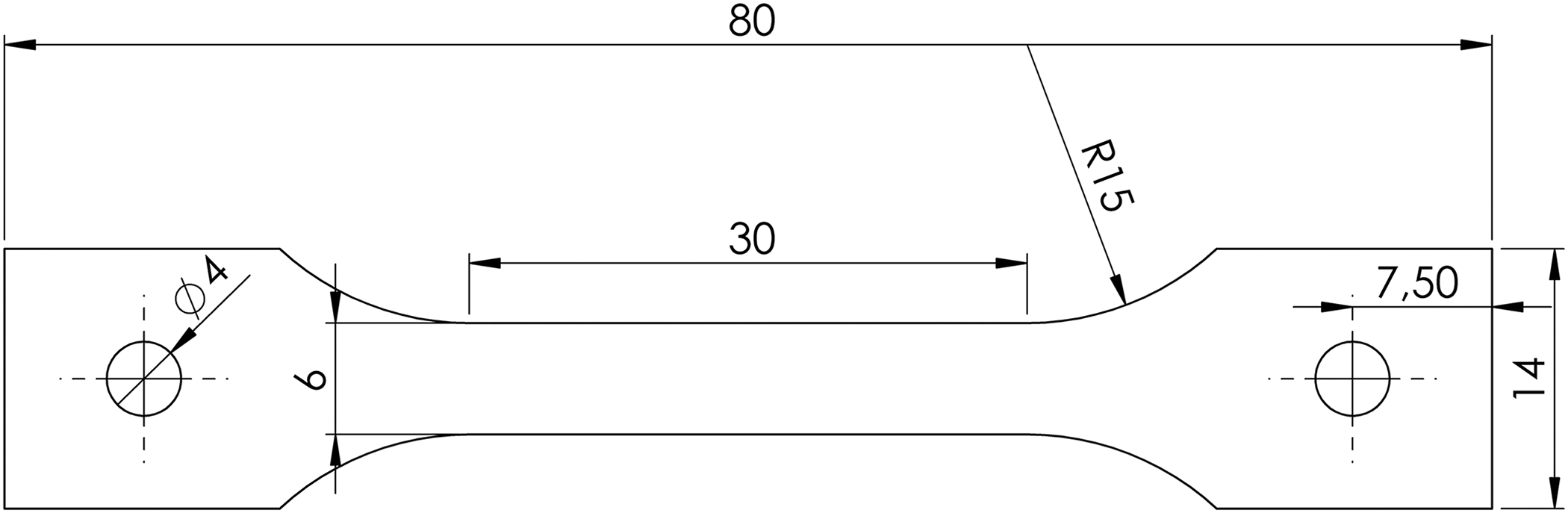
Drawing of the test specimen.
The specimens contain holes with diameters of 4 mm at their ends to facilitate their assembling in the testing machine. After assembling, the ends of specimens were tightened by the grippers to avoid the stress concentration around the holes and provide a full clamping of the specimen’s ends.
Experimental installation
The ASTM standard D2990 54 provides the main idea and requirements for the tensile creep tests and rupture strength of plastics. According to it, the existing experimental installation was prepared and modified to provide an appropriate loading value, loading rate, and elevated temperatures. Figure 2 shows a whole view of the experimental setup.

Experimental installation: (a) the general view and (b) specimen in the grippers.
The specimen I is fixed in the grippers II, while the heating element (heater) III is positioned around it. The displacement of the grippers is measured by two dial gauges IV, and the constancy of a temperature is controlled by the sensor V. The heater provides a smooth rise of temperature up to 100°C keeping it within the range of ±2°C, which is prescribed in the ASTM standard D2990.
The mechanical part of the experimental setup was assembled on the basis of the experimental machine AIMA-5-2, 55 which belongs to the type of machines used for a long-term testing of materials at elevated temperatures.
Set of experiments
The procedure and details of a set of experiments was planned according to the ASTM standards. 53,54,56 The specimens were cut out according to the drawing in Figure 1 from a single sheet of a GFRP composite plate with a thickness of 2 mm.
Such loading schemes allowed identification of the in-plane mechanical properties of the composite material. The determination of mechanical properties in the third direction (perpendicular to the plane of the plate) requires tensile or compressive tests in this direction, which is difficult to implement. However, while modeling the mechanical behavior of thin composite plates and shells subjected to tensile and bending forces, there is only a requirement for the in-plane properties.
Processing of results
Physical relations of composite material
An anisotropic linearly viscoelastic material with an absence of prestressed and prestrained conditions (lower bound is 0 instead of –∞) can be reflected by the Boltzmann’s heredity integral

where t is a time variable, ξ is a passed time, i, j, k, l = 1, 2, 3, σij (t) and εij (t) are the components of the second-order stress and strain tensors, respectively, and Sijkl (t) are the components of the fourth-order creep tensor.
We assume that the weaving scheme of the considered material results in orthotropic viscoelasticity. This allows reduction of the number of components of the fourth-order symmetric time-dependent creep tensor from 36 to 9. Then, the Voight form of equation (1) is

On the other hand, the components of the compliance tensor for the orthotropic material can be expressed by technical constants

Therefore, the time-dependent technical constants can be found from the relation (3).
The way of loading of tested specimens allows consideration of the stress–strain state in them as a plane stress state, which means that stress vectors on the surfaces, parallel to the plane of the specimen, are approximately equal to 0: σ 33(t) = 0; σ 23(t) = 0; and σ 13(t) = 0.
Thus, the simplified physical relations can be considered

In the case of the time-constant stress state, equation (4) is simplified

The experimental setup allows measuring the only longitudinal displacements of the grippers and thus the longitudinal strain. Therefore, the first experiment gives the compliance tensor component (S 1111)0 in the coordinate system (CS), coincident with the weaving directions (i.e. the natural axes of the composite), the second one gives the component (S 2222)0 in the same CS, while the third one allows gaining the component (S 1111)45 in the CS, rotated at an angle of 45° relative to the weaving scheme direction (or to the natural axes)

where P 1, P 2, and P 3 are the constant stresses applied to the working part of specimens for the first, second, and third types of experiments, respectively; and (ε 11(t))0, (ε 22(t))0, and (ε 11(t))45 are the strains, measured in time for the first, second, and third types of experiments, respectively.
The other components of the compliance tensor cannot be found without measuring an additional information. At the same time, according to the tensor components transformation rule, the component (S 1111)45 in the rotated CS can be expressed using the components in the initial CS 57

where θ = 45° is an angle of rotation of the CS.
When rearranging the relation (7), the sum of unknown components can be expressed as follows

Comparing equation (3) with equations (6) and (8), the technical constants are

Approximation of experimental data
The dependence of composite material parameters as a result of series of mechanical experiments is represented by a tabular data

where P is a function that represents a certain parameter, tm is the mth time point (m = 1..M), and Pm is a value of the parameter evaluated from the mechanical experiments.
The time approximation of viscoelastic parameters is usually performed using exponential Prony series

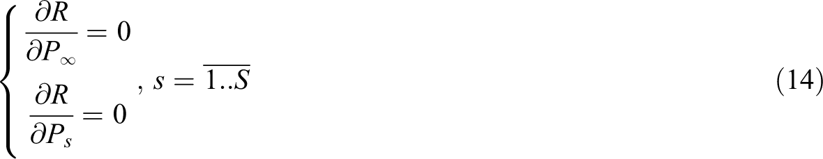
To approximate the measured data, the least squares procedure can be used. It requires the following residual

Then, we compose a system of nonlinear equations minimizing the residual

If to consider the constant relaxation time for the least square procedure, then equation (13) is simplified and becomes a system of linear equations
Numerical modeling of experiments
An accurate finite-element modeling of the experiment procedure was required to evaluate the error in measurements of deformations because it is possible to measure the displacement of the grippers but not of the specimen’s working part. The stress–strain state in the end part of the specimens is not one-dimensional, which may reduce an accuracy of the measurements significantly.
The elastic calculations were conducted in the free version of the commercial finite-element code ANSYS Workbench Mechanical (Student Version). The mechanical properties of the orthogonally directed epoxy composite material and structural steel were taken into consideration from the ANSYS material library.
Figure 3 shows the finite-element model of the specimen fixed in the gripper, where three orthogonal Cartesian symmetry conditions are applied to it. The gripper was modeled by a cuboid bonded to a side face of specimen which reflected a rigid fixation of the sample in the real experimental rig. A simple shape of the rig in the model did not bring a significant error to an adequate structural calculation but allowed to build an accurate regular finite-element mesh.

Finite-element model of the specimen.
The finite-element error of the model is less than 0.5%. The longitudinal displacement of 1 × 10⁻⁵ m was applied to the side surfaces of the gripper. Steel was applied as a material of the gripper, and epoxy woven composite was chosen as one of the specimens in the analysis model.
Two analysis were performed: (1) for the specimen model with fibers, directed at angles of 0° and 90° and (2) for the specimen model with fibers, directed at an angle of 45°. Figure 4(a) and (b) shows the contour plots of longitudinal displacements for two described cases.
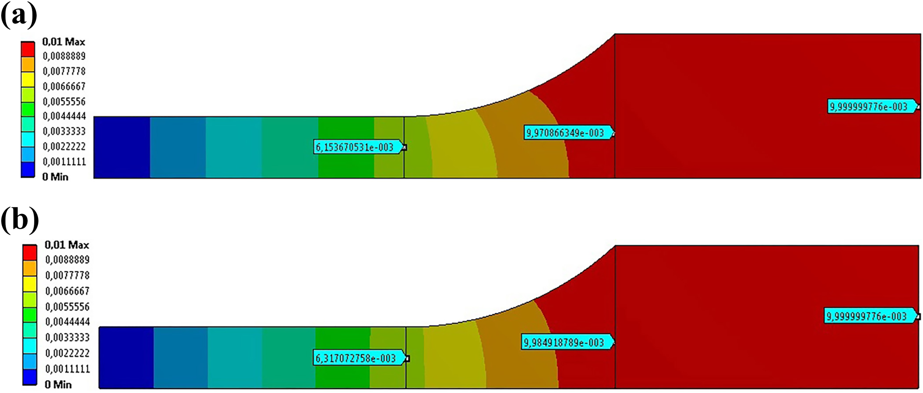
Contour graphs of longitudinal displacements, (×10−3 m): (a) the specimen with fibers, directed at angles of 0° and 90° and (b) the specimen with fibers, directed at an angle of 45°.
The evaluated displacements and correction factors are recorded and presented in Table 1. Obtained displacement fields allowed evaluation of the correction factors for each case of fiber directions to apply them to the processing of the mechanical experiment results: η = ug /uwp .
Displacements of the loaded specimen.

Results
Determination of stress–strain diagrams at room temperature
The stress–strain diagrams (SSDs) were determined for the room temperature. The specimens were loaded up to their fracture (Figure 5). This allowed defining the elastic area of deformation as well as plastic zone. For the final loads close to the fracture load, the deformation process had an obvious creep set.

Fracture of specimens: (a) specimen cut at an angle of 0° and (b) specimen cut at an angle of 45°.
The SSDs were obtained under the force control which is the only option provided by the used experimental rig for this type of tests. Even though a more reliable approach would be strain controlled tests with a linear increase in the displacement (constant strain rate), the performed mechanical experiments showed an excellent repeatability, which proved that they are adequate and the numbers of experiments for all the considered directions are proper.
Figure 6 shows the SSDs, built based on a set of three experiments for each type of specimens provided at the room temperature. The dots on plots show the averaged measured points. Young’s moduli in each direction were obtained for the elastic zones, and the solid lines on the plots show the predicted elastic behavior of the composite for the considered directions. According to the observed data, the predicted stress for relaxations tests at an elevated temperature should not exceed 70 MPa to avoid the undesirable plastic deformations that can affect the measurements of displacements during relaxation tests. In addition, shift is applied two times as a correction for the elevated temperature. Thus, stresses in the working part should not exceed 35 MPa.
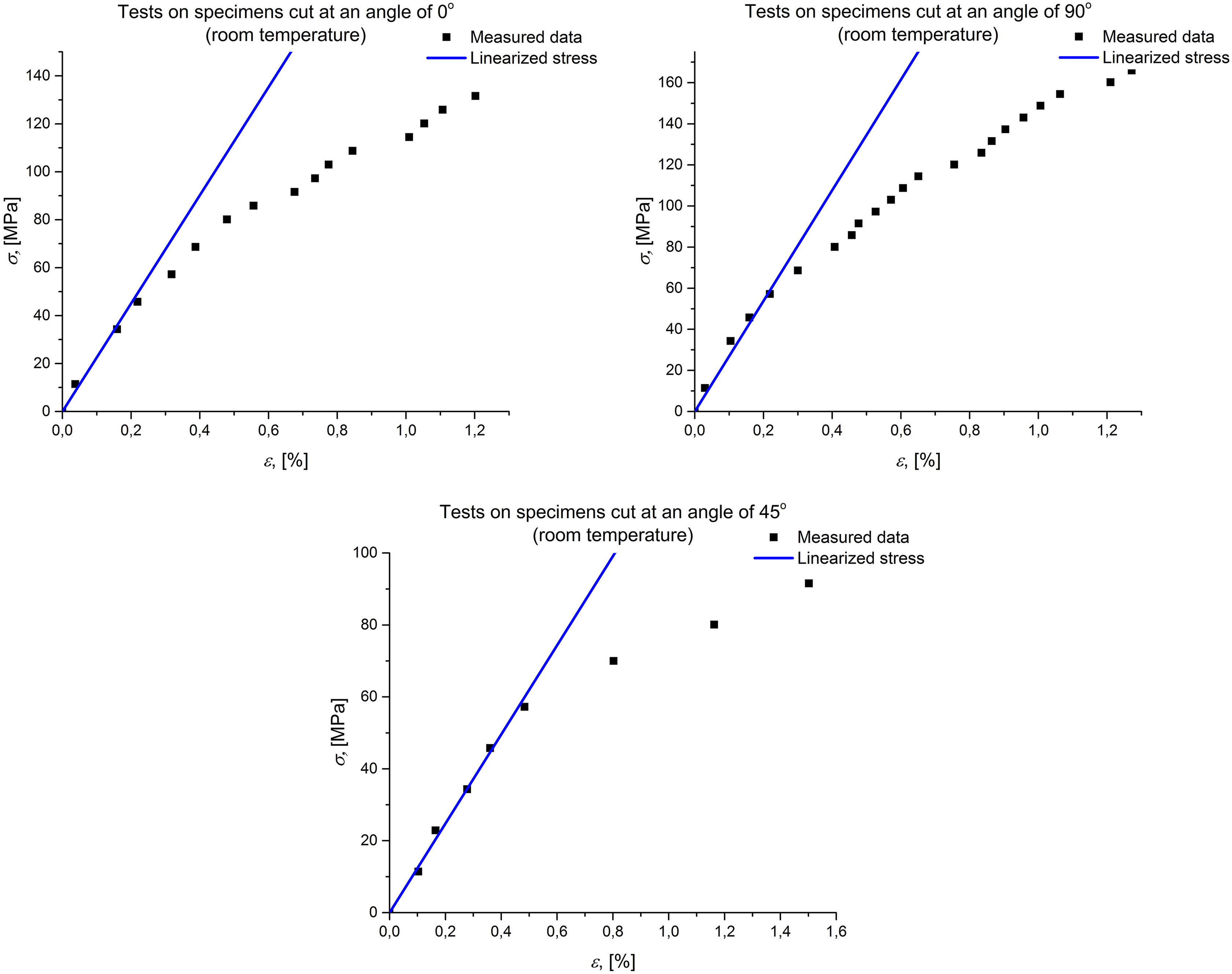
Stress–strain diagram for room temperature.
It is difficult to evaluate the Poisson’s ratio using the current experimental set. Generally, there is a lack of reliable experimental techniques that allow its accurate determination. 58,59
The values of the major Poisson’s ratio for woven and orthogonal plies of a GFRP composite at a room temperature were determined in the literature 60 -62 and on the average are equal to 0.111.
A lot of the literary sources give an approximately equal value of the in-plane Poisson’s ratio that allow considering this value for further calculations in the article.
Determination of relaxation curves at elevated temperature
As Schapery 63,64 postulated, a linear viscoelastic behavior of polymers and their composites does not result in a significant change of the Poisson’s ratio in time. Thus, the Poisson’s ratio can be identified in the beginning of the test and considered constant over time with a sufficient accuracy which was proved by the authors using a numerical experiment on a representative unit cell of an orthogonally woven composite material. 65 This can lead to some error in the determination of viscoelastic technical parameters but simplifies their identification significantly. Therefore, it was assumed that the Poisson’s ratio remained equal throughout the test.
Then, the fourth equation in the system (9) can be rearranged to express the time dependence of the shear modulus

The change of the Poisson’s ratio of woven fiberglass composite with temperature was investigated by Budhoo. 62 The author found that there is a slight decrease (approximately 1.5%) of its value comparing room temperature conditions and 75°C. The comparison of room temperature conditions and 125°C gives a decrease of 6.9%. With regard to these results, the expected decrease for 100°C is assessed as 3.8%. This decrease is applied to Poisson’s ratio, estimated for the temperature of 100°C giving a value of 0.107.
Evaluation of the in-plane shear modulus according to equation (15) was performed for each time point. Thus, there is a tabular dependence of the modulus on time.
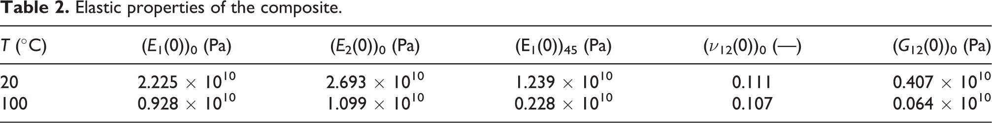
Table 2 presents the values of the measured Young’s moduli, estimated Poisson’s ratio (from literature), and evaluated shear modulus for the room temperature and 100°C.
Elastic properties of the composite.
It is difficult to obtain the SSD for the composite material at 100°C, because the viscoelastic strains affect the measurements of elastic and plastic strains significantly. Therefore, only initial elastic technical parameters are provided.
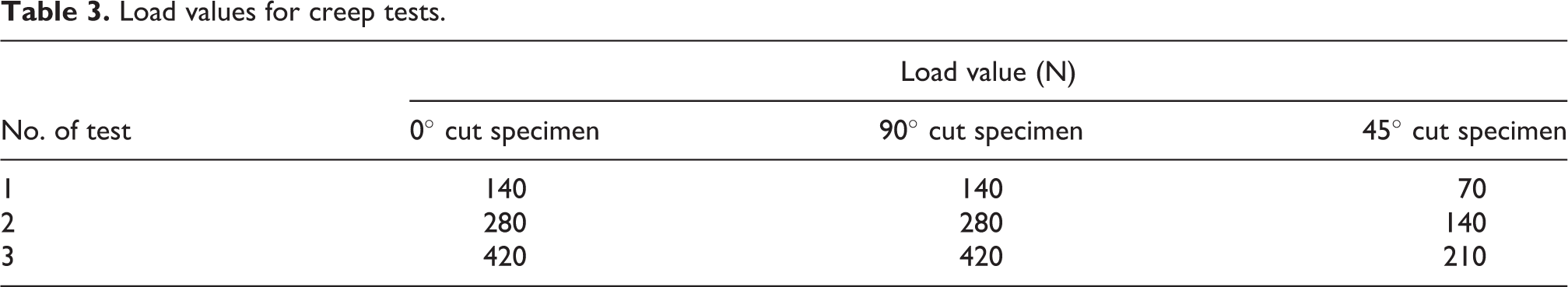
To perform creep tests, the constant loads were chosen as given in Table 3. As it follows from the table, three tests in each direction were provided.
Load values for creep tests.
The measured creep curves for each type of specimens and different values of loads are presented in Figure 7. As it follows from the graphs, there is good agreement between the curves for different loadings that proves a linearity of a viscoelastic behavior of the composite and an absence of plastic strains.
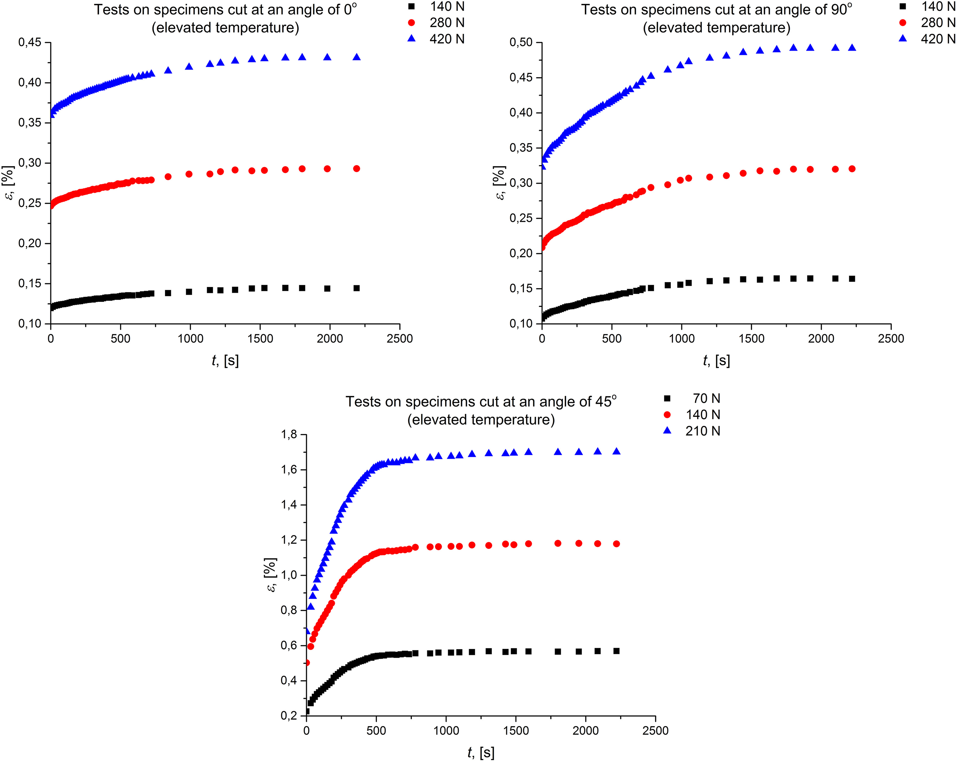
Creep curves.
Figure 8 shows the tabular time dependencies of technical parameters of the composite material (dots) and relaxation curves of these parameters (solid lines), built according to the least square procedure, discussed earlier, with a Prony series approximation.

Relaxation of technical parameters.
With the load release, the deformations were found to return to their elastic values, and the residual inelastic strains comprised less than 8% of elastic values. This fact proves an absence of significant plastic strains, which could have affected an accuracy of the measurements of viscoelastic strains. The approximation coefficients of the relaxation curves are presented in Table 4.
Approximation coefficients of technical parameters.

Discussion
The identified viscoelastic properties can be considered as linear ones. A linearity of these properties is proved by a relatively low level of viscoelastic strains (less than 2% for all the cases), stress levels that arose in the specimens and are half that of yield limits, as well as an obvious reversibility of a viscoelastic phenomenon. Therefore, the considered linear viscoelastic model is correct and adequate for the observed measurements.
As Figures 6 and 8 show, the Young’s modulus in the first direction is less than the one in the second (orthogonal) direction for the room temperature and 100°C. This means that there is a little more fibers composed in the second direction compared to the first one. At the same time, the Young’s modulus in the second direction relaxes more compared to the first one. This observation is explained by the fact that the gaps between the fibers orthogonal to the load direction are wider when loading in the second direction. Therefore, there is more matrix material subjected to the load and tend to lose its mechanical properties. Such a difference in values of the Young’s moduli can mean either nonequivalence in the number of laminas in each of orthogonal directions or non-balanced laminas in the layers. 66 However, such slight differences exist due to production imperfections.
As it follows from Table 4, the viscous properties in a shear direction are pronounced much more significantly in comparison with longitudinal ones. This can be illustrated evaluating the ratios of the technical parameters in time to their initial values. Then, we obtain scaled technical parameters

Figure 9 shows the comparison of scaled technical parameters.

Relaxation of scaled technical parameters.
As Figures 8 and 9 illustrate, in-plane shear modulus relaxes much faster than the Young’s moduli and its relaxed value is half that of the initial one. This observation coincide with conclusions in the study by Martynenko and Lvov, 65 where the numerical prediction also showed a significant relaxation of the shear modulus in comparison with the in-plane Young’s moduli.
Conclusions
The considered GFRP composite material does not exhibit viscoelastic properties at the room temperature. Identified stress–strain curves show that the composite belongs to a plastic material with a long plasticity region. Elastic modulus in the second direction is slightly higher than the one in the first direction, which assumes a small difference between the composite’s microstructure in two principal directions.
The performed relaxation tests at the elevated temperature prove this point. The initial values of Young’s moduli differ in the same way. At the same time, Young’s modulus in the second direction relaxes more than the one in the first direction for this case that is related to higher relaxation properties of the matrix material orthogonal to the loading.
Relaxation process for the temperature point of 100°C, which is higher than the glass transition temperature of an epoxy resin, completely finishes at the time of 2500 s. The in-plane Young’s moduli relaxes slower than the in-plane shear modulus which is reasonable due to a significance of the viscoelastic matrix if to subject the composite to a shear loading.
As the relaxation of scaled technical parameters does not have the same nature for each of them, the requirement to account for anisotropic viscoelastic properties of fiber-reinforced composite arises when modeling a mechanical behavior of composite structures. 67,68
Time dependencies of technical parameters approximated by Prony series are totally applicable to the existing material anisotropic viscoelastic models.
Footnotes
Acknowledgments
The authors appreciate the support of the National Technical University “Kharkiv Polytechnic Institute” in providing laboratory facilities.
Declaration of conflicting interests
The author(s) declared no potential conflicts of interest with respect to the research, authorship, and/or publication of this article.
Funding
The author(s) received no financial support for the research, authorship, and/or publication of this article.