
Abstract
Graphene-related materials such as graphene oxide (GO)/exfoliated graphene oxide (XGO) and reduced graphene oxide (RGO) recently achieved much interest in nanocomposite research. In this study, we report the synthesis of RGO by a green route, and its efficacy as a potential filler for radiation-vulcanised natural rubber latex (RVNRL) was explored. The synthesised XGO and RGO suspensions were characterised. The mechanical, morphological and electrical properties of the RVNRL-XGO/RGO nanocomposites were evaluated as a function of filler content. The percolation threshold of the RVNRL-RGO composite was 0.1 wt%. Compared with gum RVNRL, significant improvements in tensile strength and elongation at break were obtained for RVNRL-XGO nanocomposites at 1 wt% XGO loading, indicating increased polymer–filler interaction. The morphological results showed aggregation of filler particles at a concentration of 1.25 wt%.
Introduction
Radiation-vulcanised natural rubber latex (RVNRL) is commercially important as it can be directly used for the fabrication of various latex products. In RVNRL, cross-linking of rubber is brought about by γ-radiation and is different from conventional sulphur pre-vulcanised natural rubber (NR) latex. Biodegradability, absence of N-nitrosamines, very low cytotoxicity, low protein allergy response, no contamination of effluent with zinc oxide, less formation of ashes when burned, better transparency and softness and so on make RVNRL an attractive candidate for the manufacture of gloves, medical tubes, condoms, catheters, teats, endoscopic balloons, dental dams and several other medical products. 1
Nowadays polymer–graphene nanocomposites constitute an emerging field in materials science. A huge volume of literature is available in the area of graphene–elastomer nanocomposites. Xing et al. prepared graphene/NR (GE/NR) nanocomposites by a modified latex mixing method combined with in situ chemical reduction. 2 Mensah and co-workers prepared graphene oxide (GO)–reinforced acrylonitrile–butadiene rubber nanocomposites via solution mixing. 3 Graphite derivatives such as GO and reduced graphene oxide (RGO) are incorporated into natural and synthetic rubber as a filler to improve the properties as well as to impart novel functionalities. 4 -8
Graphene is a flat monolayer of carbon atoms tightly packed in to a two-dimensional honeycomb lattice, having completely conjugated sp2-hybridised planar structure and is the basic building block for zero-dimensional fullerenes, one-dimensional nanotubes and three-dimensional graphite. 9 It is considered as the ‘thinnest material in the universe’ and has remarkable properties such as high thermal conductivity, superior mechanical properties and excellent electronic transport properties. 10 The excellent conductive properties of graphene are attributed to the enhanced electron–hole mobility in its planar structure due to perfect overlap of neighbouring π-orbitals. 11
Like other nanomaterials, graphene can be synthesised via top-down or bottom-up approaches. Top-down methods include mechanical milling, mechanical exfoliation of graphite by sonication and chemical oxidation followed by exfoliation and reduction of GO. The bottom-up synthesis route includes epitaxial growth on silicon carbide and other substrates, chemical vapour deposition and arc discharging methods. 9 Zhong et al. reviewed the scalable methods of graphene production with recent progress and challenges. 12
Chemical oxidation and exfoliation followed by reduction is a widely practised method for the large-scale production of graphene. This route is simple and inexpensive. Further, oxidative exfoliation technique increases the distance between carbon layers thereby weakening the van der Waals forces of interaction and facilitating the exfoliation process. 13 The exfoliated graphene oxide (XGO) obtained after the oxidation followed by exfoliation and reduction using hydrazine derivatives yielded RGO/graphene. Considering the high toxicity associated with hydrazine, a green and eco-friendly approach for the reduction of graphene stimulates much interest nowadays.
Production of multilayer graphene dispersion by ultrasound exfoliation of graphite in a weakly basic solution is reported by Ricardo et al. 14 Loryuenyong et al. synthesised RGO sheets via water-based exfoliation and reduction method and characterised using Fourier-transform infrared (FTIR) spectroscopy, X-ray diffraction (XRD), thermogravimetric analysis, Raman spectroscopy, scanning electron microscopy and transmission electron microscopy (TEM) methods. 15 Liao et al. synthesised graphene sheets from graphite oxide by reduction with simple deionised water at 95°C under atmospheric pressure. 16 Haghighi and Tabrizi used rose water as a green reducing agent for the synthesis of RGO nanosheets. Through XRD analysis, they have reported that the oxygen-containing functional groups of exfoliated GO can be removed easily after its reduction by rose water. 17 A detailed review on the techniques and mechanisms associated with the reduction of GO is available. 18
Solution mixing is a simple and effective method for the preparation of graphene-based nanocomposites. The process involves mixing of colloidal suspensions of graphene-based materials with the desired elastomer either its latex form or by dissolving in a solvent. 19 In this article, a hydrazine-free route for the synthesis of RGO and the preparation of RVNRL-RGO/XGO nanocomposites via simple solution mixing was demonstrated.
For the preparation of RGO, graphite flakes were first oxidised to GO and which was then exfoliated by sonication. The XGO dispersion thus obtained was then reduced to RGO by continuous stirring in a closed container kept in an oil bath. The aqueous dispersions of XGO and RGO were mixed with the RVNRL and the composite films were cast. Finally, the morphological, mechanical and the electrical properties of the resultant nanocomposites were evaluated as a function of filler content (XGO/RGO). Also, the experimentally evaluated mechanical properties of the RVNRL-RGO nanocomposites were interpreted with theoretical calculations.
Experimental
Materials and methods
RVNRL having a total solid content of 53.49% was supplied by the Malaysian Nuclear Agency (Selangor, Malaysia). The formulation for the preparation of RVNRL is shown in Table 1. The latex used for this work was of high-ammonia type and RVNRL was prepared as per the formulation (Table 1) and was irradiated to a total dose of 12 kGy at a dose rate of 2 kGy/h. The sensitiser used was n-butyl acrylate. The stabiliser used was potassium laurylic acid, and the antioxidant used was Irganox 1520 supplied by Ciba Speciality Chemicals (Switzerland).
Formulation used for the preparation of RVNRL.

RVNRL: radiation-vulcanised natural rubber latex; n-BA: n-butyl acrylate.
Coarse low-density flake graphite (Grade 3780) from Asbury Carbons (Asbury, NJ, USA) was used for the preparation of graphene derivatives (XGO and RGO). The specification of the graphite used is shown in Table 2. Concentrated sulphuric acid (H2SO4; 98%, GR grade) and 30% hydrogen peroxide (H2O2) solution (purified) were purchased from Merck (Mumbai, Maharashtra, India). Potassium permanganate (KMnO4) and potassium hydroxide (KOH) procured from Qualigens Fine Chemicals (Mumbai, Maharashtra, India) and Triton X-100 from Sigma-Aldrich (USA) were used as such. In all the experiments, Millipore (Merck, India) distilled water was used.
Specifications of graphite used.

Preparation of XGO dispersion
GO was synthesised from flake graphite using modified Hummers method reported by Loryuenyong et al. with some modifications. 15 The detailed synthesis procedure was as follows: Briefly, 6 g graphite was added to 300 mL concentrated H2SO4 taken in a round-bottom (RB) flask with continuous stirring. The mixture was cooled in an ice bath. After completely adding graphite, 24 g KMnO4 was added slowly into the above mixture with continuous stirring and cooling. After 30 min stirring, the mixture was removed from the ice bath and again stirred for 45 min at room temperature. Then 150 mL distilled water was added slowly into the above mixture and stirred for 15 min. Finally, 40 mL 30% H2O2 solution was added to the above mixture and stirred well. The solid fraction was filtered, washed and centrifuged three times with distilled water at 10,000 r/min for 5 min. The obtained GO was dried at 45°C for about 48 h in an air oven. For the preparation of GO dispersion, around 0.255 g GO powder was added to 150 mL distilled water and stirred at 700 r/min for about 5 h. The concentration of the resulting suspension was 0.043 wt%.
The GO dispersion was ultrasonicated for about 30 min to obtain an XGO dispersion. To avoid overheating, the mixture was cooled occasionally in an ice bath.
Preparation of RGO dispersion
GO powder (0.266 g) was dispersed in 100 mL distilled water stirred at 600 r/min for 5 h and then sonicated for 30 min with occasional cooling in an ice bath. The resulting XGO suspension was transferred into a RB flask kept in an oil bath followed by continuous stirring and heating at 95°C for 4 days. The concentration of the RGO suspension was 0.00389%.
Preparation of nanocomposites
Before adding XGO and RGO dispersions to RVNRL, the pH of the latex was adjusted to approximately 11 using 10% KOH solution. For the preparation of XGO-RVNRL nanocomposites, appropriate amount of XGO dispersion was added to RVNRL. Details showing the amount of XGO/RGO added for the fabrication of nanocomposites are shown in Table 3. RVNRL-XGO and RVNRL-RGO represents radiation vulcanised-natural rubber latex–exfoliated graphene oxide and reduced graphene oxide nanocomposites, respectively. The filler concentrations were kept at 0, 0.1, 0.25, 0.5, 1 and 1.25 wt%.
Amount of filler (XGO and RGO) used for the preparation of nanocomposites.

RVNRL: radiation-vulcanised natural rubber latex; XGO: exfoliated graphene oxide; RGO: reduced graphene oxide.
The latex mixture was stirred well and matured for 45 min, and films were cast as per the formulation made above (Table 3) and kept in a hot air oven for drying at 60°C for 40 min. The films were then leached in distilled water and dried again until they were free from moisture and were used for various property measurements.
For the preparation of RGO-RVNRL nanocomposites, RGO was initially dispersed in Triton X-100 (1% solution) by vigorous stirring for 30 min and was prepared as given in Table 3. The filler content (XGO and RGO) in the composite has been varied from 0 wt% to 1.25 wt% (i.e. 0, 0.1, 0.25, 0.5, 1 and 1.25 wt%). The amount of filler (XGO and RGO) required for this has been calculated based on dry weight of the polymer. For example, 20 g latex having a total solid content of 53.49% may contain 10.698 g dry rubber. Therefore the amount of filler required for the preparation of composite having 1.25 wt% of XGO/RGO is 13.352 (10.698 × 1.25). Similarly, the amount of filler required to prepare latex composites having various concentrations of filler (XGO/RGO) can be calculated.
Characterisation
Particle size analysis of GO and XGO was monitored in a particle size analyser (Zetasizer Nano S, Malvern, UK) using dynamic light scattering technique. Vibra Cell ultrasonicator (model VCX-750) at a frequency of 20 kHz having a power of 750 W was used for the exfoliation of GO to XGO (Newton, CT). The FTIR spectra were recorded on Varian FTIR spectrometer (Varian 660-IR model) in the wavelength range 600–3600 cm−1. The ultraviolet (UV)–visible spectra of XGO and RGO were recorded on a Spectro UV-VIS double beam spectrometer (model UVD-3500) of Labomed Inc. (Los Angeles, California, USA).
High-resolution Raman spectrometer (HORIBA JY, Japan) band analysis with a resolution in the order of 0.3–1 cm−1 was used to record the Raman spectra of XGO and RGO. An argon ion laser operating at 514 nm was used for this purpose. Atomic force microscopy (AFM) analysis of RGO was measured on a WITec Alpha 300RA (WITec GmbH, Ulm, Germany) using tapping mode on a thin film cast on a glass substrate. High-resolution TEM (HRTEM) was carried out in a Jeol/JEM 2100 (Tokyo, Japan) instrument operated in a voltage of 200 kV having a magnification capacity of 2000×–1,500,000×.
The morphological images of the nanocomposites were taken on WILD HEERBRUGG (M8) zoom stereomicroscope (Switzerland) connected with LEICA digital camera (model DFC 320; Germany). The mechanical properties of the composite films were measured using a Zwick (Germany) universal testing machine (Model 1474) according to ASTM D 412.
The electrical conductivity of the XGO- and RGO-incorporated composite films was measured using a two-probe multimeter. The cut specimens having dimensions of 1.3 × 1.3 cm2 were kept between two copper plates and a constant voltage of 6 V from a direct current source (Systronics (Gujarat, India) model 615 D) was applied and the current flowing through them was monitored using a digital multimeter (Fluke (USA) 187). The conductivity of the sample was measured using the following equation

where t is the thickness of the specimen, A is the area of cross section of the sheet and R is the resistance of the film. R can be calculated using the equation

where E is the applied voltage and I is the current passing through the specimen.
Results and discussion
Particle size analysis of GO and XGO
Particle size analysis results of GO and XGO are shown in Figure 1. It is clear from the figure that the size and size distribution of XGO decreased considerably after ultrasonication. The size range of sub-micrometre-sized GO particles was 712–825 nm, whereas it was in the range of 295–531 nm for XGO. A slight increase in the size of nanoparticles (size <100 nm) might be due to agglomeration of lower-sized particles generated after prolonged sonication. A significant size reduction of XGO indicates the large extent of exfoliation of GO after ultrasonication.
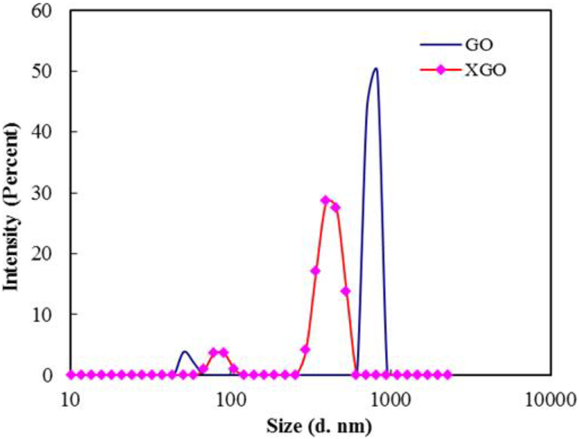
Particle size distributions of GO and XGO.
FTIR analysis
Figure 2 represents FTIR spectra of XGO and RGO. The stretching vibrations of O–H (3450 cm−1), C=O (1728 cm−1) and C–O (epoxy) (1229 and 1071 cm−1) were observed for XGO. 15 The evidence for the reduction of XGO to RGO is confirmed by the disappearance of C=O peak (1728 cm−1) and C–O alkoxy stretching (1071 cm−1). Significant weakening of O–H peak (3450 cm−1) also indicates the efficient reduction of XGO to RGO. 20

FTIR spectra of graphite, XGO and RGO.
UV-visible analysis
The UV-visible spectrum of XGO and RGO is displayed in Figure 3. The absorption peak at 224 nm is attributed to π–π* transition of aromatic C=C bonds, 21 whereas the RGO peak is shifted to 246 nm due to decrease in oxygen functional groups and an increase in the number of aromatic rings, causing electrons to be excited easily at lower energy. 15 The red shift of the peak to 246 nm (>238 nm) indicates the restoration of a π-conjugated network in RGO. 22 The inset shows stable high concentration aqueous dispersions of XGO and RGO.

UV-visible absorbance spectra of XGO and RGO. Inset shows photographic images of XGO and RGO suspensions in water.
Raman analysis
Raman spectroscopy can be used to investigate the structural changes happening during the oxidation and reduction process. Figure 4 exhibits the Raman spectra of XGO and RGO. Raman spectrum of RGO contains both D and G bands at 1345 and 1579 cm−1 with an increased I D/I G ratio corresponding to a decrease in the average size of sp2 domains. 23,24 The Raman spectrum of XGO showed a broad and highly intense D band compared to RGO, indicating greater disorder or defects in the former. 25 The structural defects induced by oxygen-containing functional groups during oxidation of graphite intensified the D band. 13 In the hydrothermal reduction route, besides dehydrating/reducing the XGO, it also recovers the aromatic structures. 22 The I D/I G ratio of RGO reported here is much lower (1.03) than that of hydrazine-reduced GO (1.44) reported by Zhou et al.
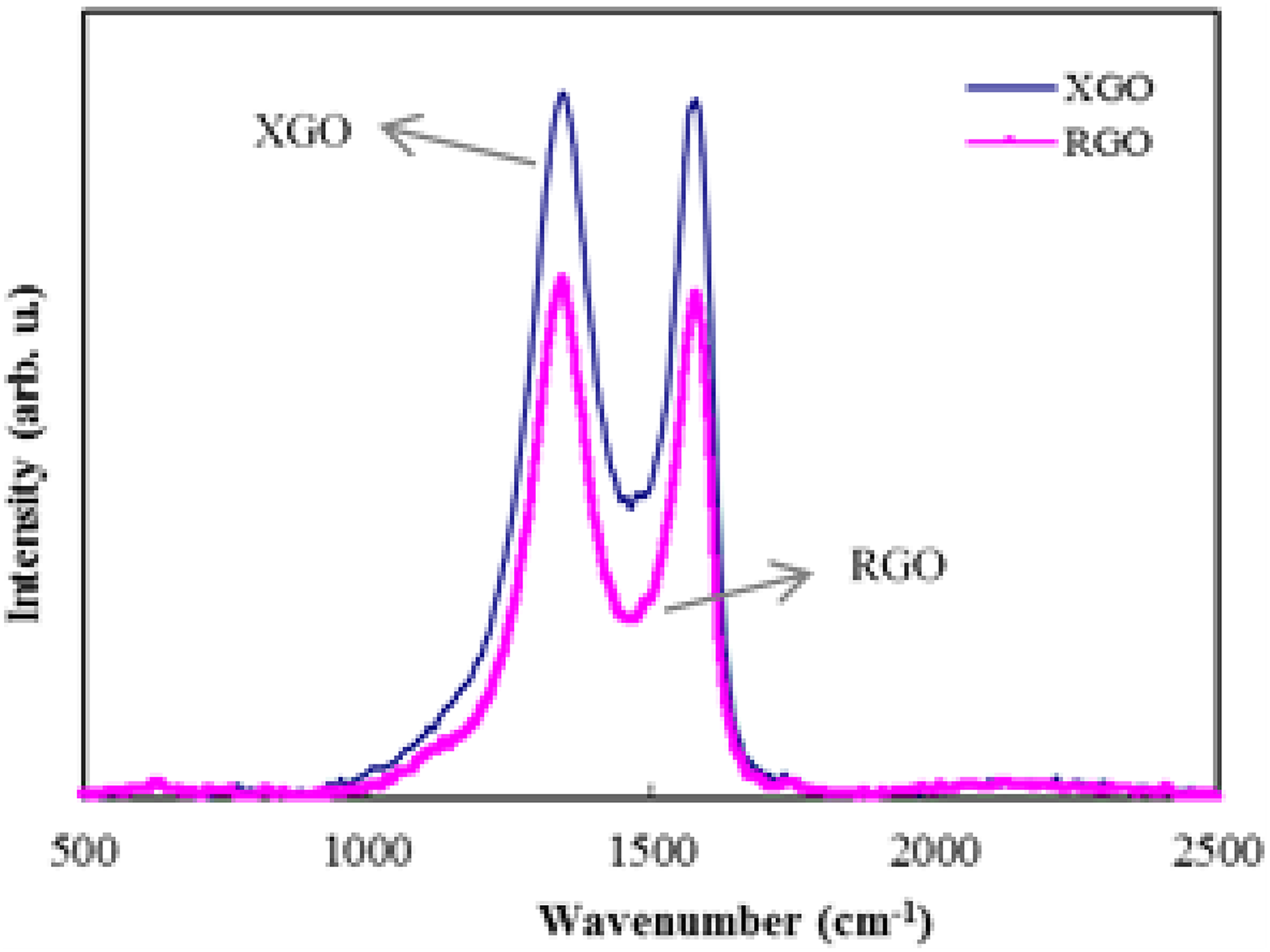
Raman spectra of XGO and RGO.
AFM analysis of RGO
A tapping mode AFM image and the corresponding height profile of RGO sheets deposited on a glass substrate by drop casting are shown in Figure 5. The scan area was 5 × 5 µm2. Height profile shows mono-, bi- and multilayered sheets of graphene. The thickness of monolayer graphene was found to be 1.32 nm. The thickness values are in accordance with monolayered (1.25 ± 0.08 nm) and bilayered (2.23 ± 0.11 nm) graphene reported earlier. 26

Tapping mode AFM image of RGO with corresponding height profile. Scan area 1 × 1 µm2.
TEM analysis of RGO
The quality of exfoliated graphene can be assessed by TEM and is shown in Figure 6(a) and (b). TEM analysis reveals the presence of single- and multilayered sheets of RGO. A partially aggregated wrinkled structure of graphene can be seen from Figure 6(a). After analysing a large number of TEM images, it was found that the major portion of the dispersion contains monolayer graphene; however, partially folded, crumpled sheets were also present. A HRTEM image of partially folded/aggregated sheets of graphene is shown in Figure 6(b).
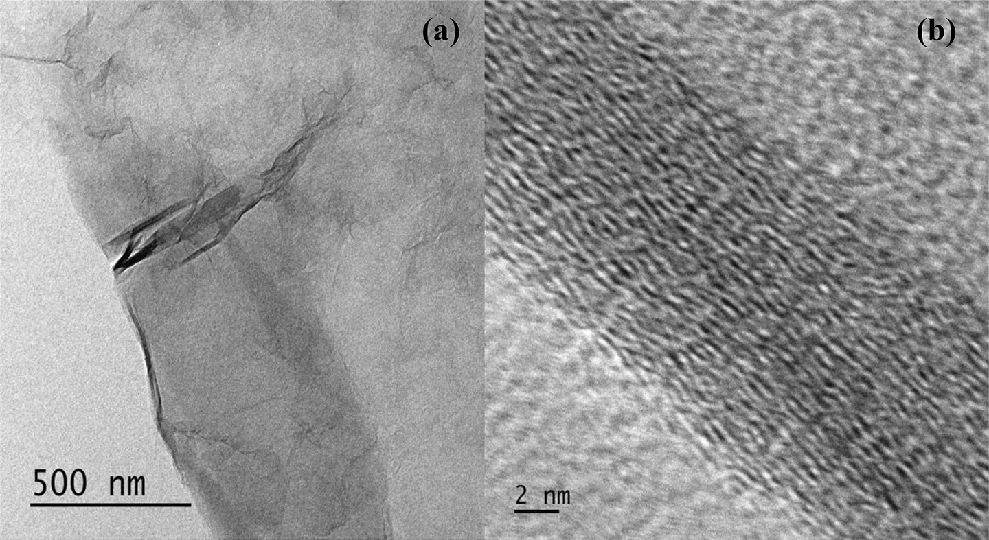
(a) TEM image of RGO with partial foldings and (b) HRTEM image of (a).
Visual features of the composite
Optical photographs of dried latex composite films containing XGO and RGO are shown in Figure 7(a) to (j). The stable aqueous dispersion of XGO is uniformly dispersed throughout the polymer matrix up to a loading of 1 wt% XGO. Above this concentration (1.25 wt%), slight agglomeration was observed, whereas for RGO-incorporated composite films, homogeneous distribution of RGO in the polymer matrix could be achieved up to 0.5 wt%, and further loading resulted in a higher rate of agglomerate formation.
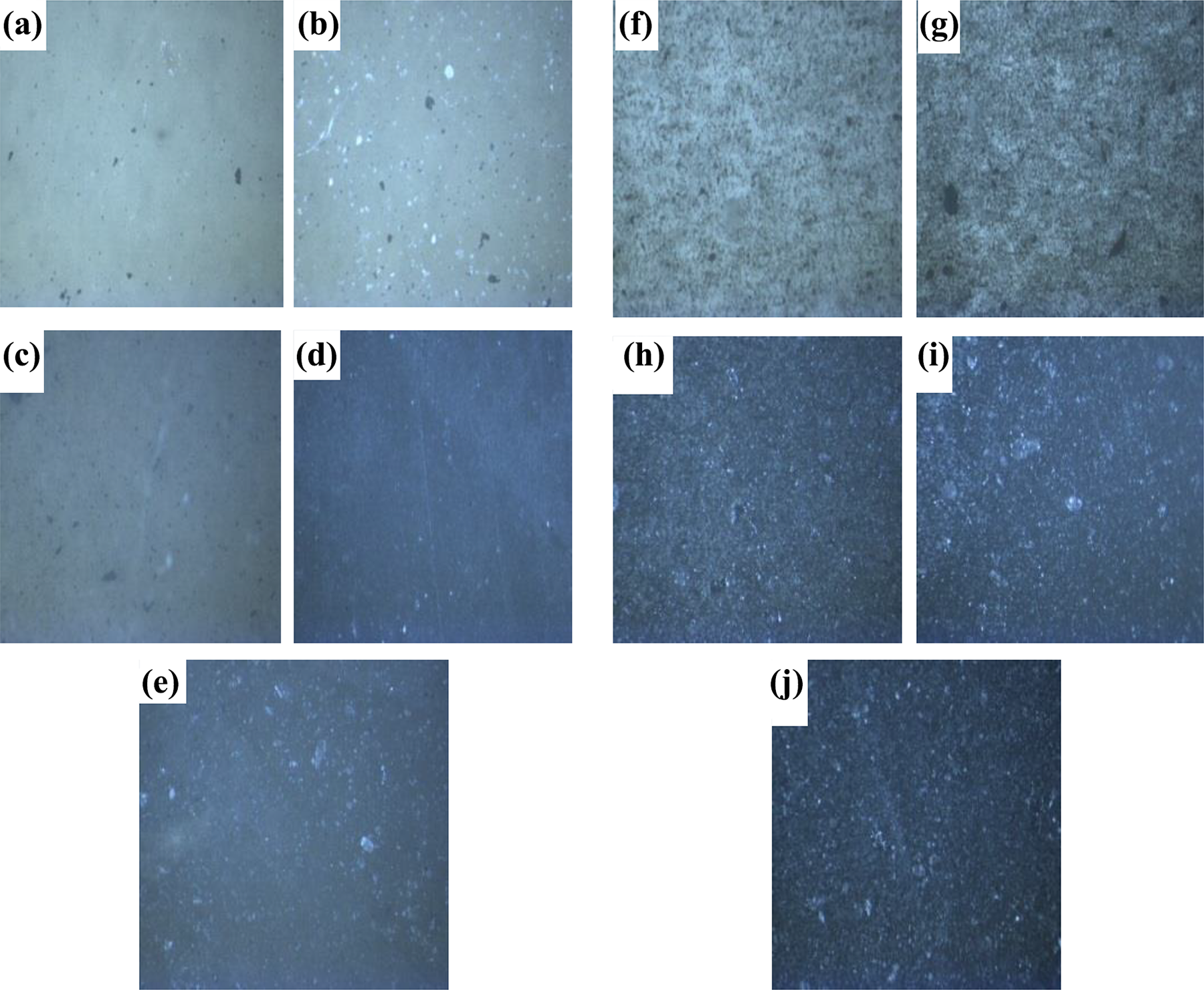
(a to j) Photographic images of RVNRL-XGO/RGO nanocomposites: (a to e) with 0.1, 0.25, 0.5, 1 and 1.25 wt% of XGO and (f to j) with 0.1, 0.25, 0.5, 1 and 1.25 wt% of RGO, respectively.
Electrical conductivity studies
The effect of filler concentration on the conductivity of RVNRL nanocomposite films is displayed in Figure 8. The pure RVNRL showed a conductivity of 10−4 S/cm. Even at a low percolation threshold of 0.1 wt%, the conductivity of RVNRL-RGO nanocomposite was of the order of 10−3 S/cm, that is, almost a 10-fold increase in conductivity. The addition of RGO yielded a significant improvement in conductivity. The uniform distribution of RGO in the polymer matrix (Figure 7(h)) resulted in the formation of a continuous network of RGO and gave rise to high electrical conductivity. Potts et al. reported higher electrical conductivity of solution-treated RGO-NR nanocomposites compared to mill-mixed composites. The explanation for high electrical conductivity in the former is attributed to the provision of more conducting pathways, whereas in the latter case, RGO platelets will get coated with a sheath of polymer, which inhibits the electrical conductivity. 27 The addition of XGO did not improve the conductivity. GO itself is an insulating material because it lacks a delocalised π-conjugated orbital system. 28

Electrical conductivity as a function of filler content for RVNRL nanocomposites containing XGO and RGO.
Mechanical properties
The mechanical properties (tensile strength, elongation at break and modulus at 100% elongation (M 100)) of XGO- and RGO-incorporated latex composite films are represented in Figure 9(a) to (c). It is clear that the tensile strength and elongation at break increase with the XGO loading and reach a maximum at 1 wt% XGO content; above this concentration, the properties decrease (Figure 9(a) and (b)). The increase in tensile strength and elongation at break is due to more uniform distribution of XGO in the polymer matrix (Figure 7(d)). XGO-RVNRL composite film showed a tensile strength of 24 MPa at 1 wt% filler loading, which is 60% higher than the initial value. The increased rubber–filler interaction results in effective stress transfer from rubber to filler particles, and in turn increases the tensile strength. On the other hand, the tensile strength of RGO-incorporated latex composites registered the highest tensile value of 17.1 MPa at 0.25 wt% RGO loading and then it gradually decreased with RGO content. The variation in elongation at break of RGO-RVNRL composite followed the same trend. The maximum elongation at break of 1488 was noticed for latex films with 0.25 wt% RGO loading. The reduction in tensile strength and elongation at break of latex composites at higher RGO loading (1 wt%) can be attributed to agglomeration of RGO nanosheets in the polymer matrix as evident from Figure 7(i). The unexfoliated agglomerates resulted in more stress concentration, and that led to reduced tensile strength. 29 The strong interaction between the polymer matrix and the filler was reflected in the modulus results (Figure 9(c)). The modulus (M 100) value increased with the filler content. At 1.25 wt% filler loading, the moduli of RGO- and XGO-incorporated composite films were 3.18 MPa and 1.33 MPa, respectively.

(a to c) Mechanical properties of RVNRL nanocomposites with various amounts of filler (XGO and RGO): variation of tensile strength (a), elongation at break (b) and modulus (c) with filler content.
Theoretical modelling
Halpin–Tsai model is an effective tool to predict the mechanical properties of filled composites. 30 -33 The orientation of filler particles in the polymer matrix can be effectively predicted using this modelling. The modulus of randomly oriented RGO (Er ) and unidirectionally oriented RGO (Eu ) in the RVNRL matrix can be calculated using equations (3) and (4), respectively 34


where lg and tg are the average length and thickness of RGO, Vg is the volume fraction of RGO, Eg is the Young’s modulus of RGO and Em is the M 100 of the unfilled RVNRL. ξ is a shape-fitting parameter, and depends on filler geometry and orientation.
It is obvious from Figure 10 that the M 100 values obtained from experimental calculation agree with the theoretical predictions and the values fit well with values (M 100) of RVNRL-RGO nanocomposite films with random arrangement of RGO in the RVNRL matrix.

Experimental values of tensile modulus (M 100) and Halpin–Tsai theoretical model fitting for RVNRL-RGO nanocomposites.
Conclusions
For the synthesis of graphene sheets, a hydrazine-free ‘green route’ was attempted and RVNRL-graphene-based nanocomposites have been prepared via simple solution mixing. Uniform dispersion of filler (XGO and RGO) in the polymer matrix and improved polymer–filler interaction are reflected in mechanical properties. Theoretical predictions showed a random distribution of graphene sheets in the RVNRL matrix. The effect of filler content on the electrical properties of nanocomposites showed a lower percolation threshold (0.1 wt% for RGO). The water-based reduction method is convenient and eco-friendly. The study opens up new possibilities for the preparation of RVNRL-based nanocomposites for novel applications.
Footnotes
Acknowledgement
The authors acknowledge the Rubber Research Institute of India (RRII), Rubber Board, Ministry of Commerce and Industry, Government of India, for the financial support. The authors extend their thanks to Sofian Ibrahim of the Malaysian Nuclear Agency and Chai Chee Keong for providing RVNRL and Albert V Tamashauski, Director of Research and Technical Services (ASBURY Carbons), for providing graphite samples. The authors thank Professor MK Jayaraj (CUSAT, India) for providing Raman facilities. The HRTEM and AFM analyses were carried out at STIC, CUSAT and SAIF, MGU respectively.
Declaration of conflicting interests
The authors declared no potential conflicts of interest with respect to the research, authorship and/or publication of this article.
Funding
The authors disclosed receipt of the financial support for the research, authorship and/or publication of this article: This work was financially supported by the Rubber Research Institute of India (RRII), Rubber Board, Ministry of Commerce and Industry, Government of India (Project code 01: 2/88/RF-RF Scheme/2010/Res).