
Abstract
Graphene/nano-sulphur (S)/polyaniline (PANI) ternary nanocomposite was successfully synthesised and used as an electrode material for supercapacitors. In this process, the aniline was selected to accomplish two functions: In the first place, it served as a reducing agent, promoting the reduction of graphene oxide to graphene, without any additional reducing agent. In the second place, it played an important role in the formation of PANI. S nanoparticles were uniformly decorated on the graphene surface, and PANI covered the graphene/S surface. Furthermore, graphene and PANI prevented polysulphide species diffusion. The products were characterised by field-emission scanning electron microscopy, X-ray diffraction, Fourier-transform infrared spectra, X-ray photoelectron spectroscopy, Raman spectroscopy and electrochemical analysis. Owing to the specific combination of the advantages of graphene, nano-S and PANI, the composite exhibited outstanding electrochemical performance showing a specific capacitance as high as 619 F g−1 at a scan rate of 5 mV s−1 and excellent electrochemical stability with a retention of 77.9% (457 F g−1) of initial capacitance (586.8 F g−1) after 500 cycles at a current density of 1 A g−1.
Introduction
Driven by the growing demand for sustainable energy and portable electronics, the storage devices with high power and energy densities have become an urgent and necessary issue with a view to make drastic reductions in utilisable fossil fuel reserves and the corresponding emissions of environment pollutants. 1 Supercapacitors, which are also named electrochemical capacitors and ultracapacitors, have attracted considerable attention as candidates because of their high power density, long cycle life and excellent reversibility. Based on the different energy storage mechanisms, supercapacitors can be classified into two categories. One is the electrical double-layer capacitor, which stores energy via an electrostatic process. The other type is the pseudocapacitor, which is based on the rapid redox reactions present in the electrode. 2 Hence, there are two ways to produce high specific capacitance: increasing the surface area to raise the double-layer capacitance while utilising a fast faradaic redox reaction to boost the pseudocapacitor capacitance.
With the rapid growth in portable electronic equipment, carbon materials, conducting polymers and inorganic oxides have been widely investigated owing to their good electrical conductivity, large surface area and outstanding long-term electrochemical stability as well as electrical conductivity and environmental stability. 3 Carbon materials, such as graphene and active carbon materials, are commonly used for double-layer capacitors because of their good electric conductivity, large surface area and outstanding long-term electrochemical stability. 4 -6 In contrast to the common carbon materials, graphene has extraordinary properties, such as tensile strength, low density and high elasticity. 7,8 In addition, elemental sulphur (S), a well-used electrode material, is reported to show many advantages, such as natural abundance, low cost, high theoretical capacity and environmental friendliness, especially when mixed with carbon materials. 9,10 Despite the mentioned advantages, the commercialisation of such composition is still limited because of their poor cycle performance caused by the rapid dissolution and transportation of polysulphide intermediates in the electrolyte as well as the mechanical instability of the electrode caused by volume changes during charging/discharging cycles. 11 -14 Herein, many efforts have been made to fabricate S/carbon-based materials composites in which carbon matrices can disperse S and hold the soluble polysulphides effectively, owing to its unique structures. 15 For example, Zhou et al. have reported a one-step hydrothermal preparation and electrochemical performance of graphene/S cathode composites, showing outstanding electrochemical properties. Therefore, a promising approach to enhance the electrochemical properties by combining graphene with pristine S, which can contribute to offer a better property of capacity when mixing with carbon materials, is suggested. However, the graphene/S composite cannot meet the urgent demand for supercapacitors in electrochemical applications because of its poor cycle life. It is worth mentioning that electronically conducting polymers (ECPs) have attracted tremendous attentions because of their metal-like electrical properties and high polymeric characteristics like flexibility and low density. 16 Polyaniline (PANI), a specific kind of material among ECPs, plays an increasingly important role owing to its low cost, easy synthesise, high conductivity and stability in air or water. 17 According to the previous literature, sulfur/polyaniline/carbon composite with a core–shell structure is proven to deliver high-rate charge/discharge owing to the high electrical conductivity of the carbon black in the core and PANI in the shell. 18 Hence, the combination of graphene/nano-S/PANI ternary nanocomposite should overcome the above problem.
In this report, pure S was fabricated by the disproportionation reaction of sodium thiosulphate (Na2S2O3) under acid conditions, and graphene oxide (GO)/S was prepared by using a mixture of Na2S2O3 and GO solution. After adding ammonium persulphate (APS), L-Lysine and aniline, GO was reduced to graphene by aniline, APS was an oxidising agent for polymerisation of aniline and L-Lysine acted as a kind of surfactant making PANI cover the graphene/nano-S surface uniformly, as shown in Figure 1.
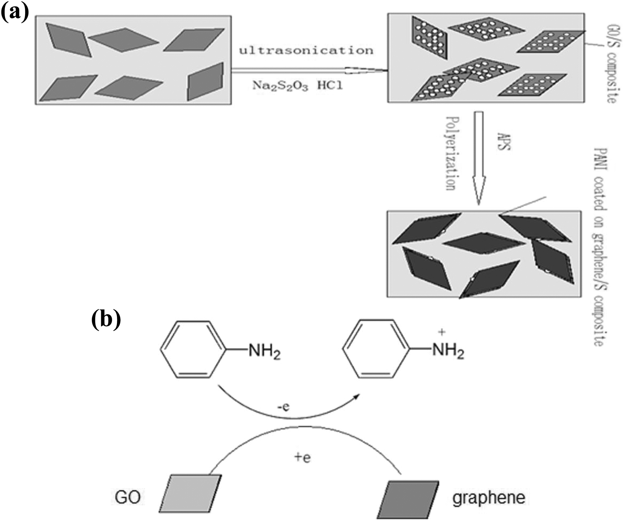
(a) Schematic illustration of the formation process of graphene/nano-S/PANI nanocomposite and (b) proposed mechanism of GO to graphene conversion.
Experimental part
Synthesis of graphene/nano-S/PANI nanocomposite
GO was prepared from natural graphite powder by the modified Hummers’ method as described in a previous report. 19
The synthesis of graphene/nano-S/PANI nanocomposite can be depicted as follows: Firstly, 125 mg GO was dispersed in 50 mL deionised (DI) water under ultrasonic treatment for 60 min. Then 0.744 g Na2S2O3·3H2O was added and dissolved into the graphene suspension. Meanwhile, 1.2 mL 10 M hydrochloric acid was added into the above solution, which was ultrasonically stirred for 30 min to obtain GO/nano-S composite suspension. Secondly, 0.2 mmol L-Lysine, 150 μL aniline monomer and 0.381 g APS were added into the above GO/nano-S solution according to priority. After being stirred for about 4 h, the reaction product was washed several times by DI water and separated by centrifugation and ultrasonically dispersed into 100 mL aqueous solution to obtain the graphene/nano-S/PANI composite suspension. Then, graphene/nano-S/PANI suspension (6.0 mL) was mixed uniformly with oxalic acid (0.02 g). Finally, hydrothermal treated at 95°C for 24 h. After the autoclave was naturally cooled to room temperature, the final products were centrifuged, washed with DI water and ethanol three times in order to remove residual unreacted compounds. Finally, the sample was vacuum dried at 70°C for 12 h to get the graphene/nano-S/PANI nanocomposite.
For comparison, pure PANI was also prepared by the same process without the presence of GO/nano-S composite.
Electrochemical measurements
All of the electrochemical experiments were conducted in a three-electrode system, in which a platinum net was used as the working electrode, and a platinum foil and a saturated calomel electrode worked as counter electrode and reference electrode, respectively. Electrochemical performance was characterised by cyclic voltammetry (CV) and galvanostatic charge/discharge on a CHI660 electrochemical workstation in an aqueous 1 M lithium sulphate electrolyte solution at room temperature.
Working electrode was prepared by mixing 80 wt% of active substance, 10 wt% of poly(vinylidene fluoride) and 10 wt% of acetylene black to form slurry, and then the slurry was spread onto nickel foam. Then the working electrode was dried in a vacuum oven at 60°C for 12 h for further use.
Results and discussion
X-ray diffraction analysis
A powder X-ray diffraction (XRD) system equipped with copper radiation was employed to determine the crystallographic structures of the materials. XRD patterns of GO, PANI, pristine nano-S and graphene/nano-S/PANI ternary nanocomposite were shown in Figure 2. The characteristic peak of GO was observed at around 11°, shown in image. For pure PANI, the crystalline peaks appeared at 2θ values of 18.5° and 25.2° corresponding to 020 and 200 reflections of PANI, which can be attributed to its emeraldine salt form. 20 All the diffraction peaks of pure S are shown in Figure 2 indexing to S (JCPDS: 08-0247), thereby indicating the high purity of the as-synthesised S. The peaks from S can be still observed in the graphene/nano-S/PANI samples, thereby manifesting successful nano-S formation in the graphene/nano-S/PANI samples. After polymerisation, the peak at around 11° completely disappeared in graphene/nano-S/PANI composite, indicating that aniline had reduced GO to graphene. 21 Notably, no peaks from graphene could be detected in the XRD pattern of graphene/S/PANI owing to the low graphene content in the composite.
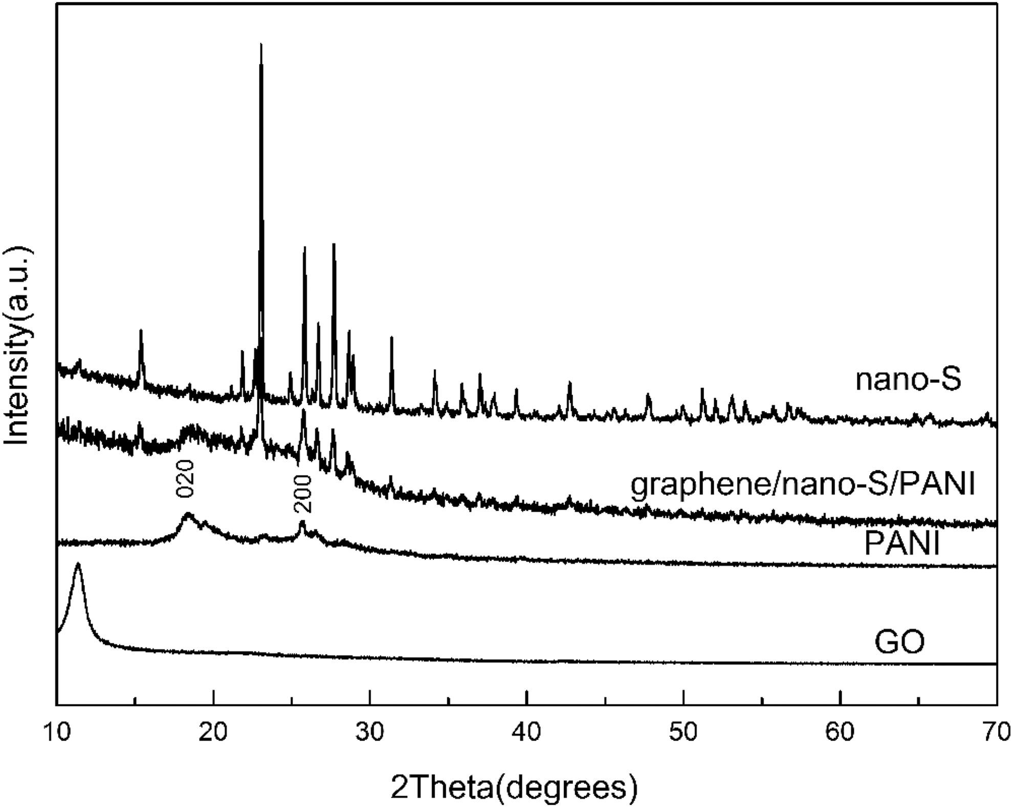
XRD patterns of GO, PANI, pristine nano-S and graphene/nano-S/PANI nanocomposite.
Morphological analysis
The morphology and structure of GO/nano-S and graphene/nano-S/PANI nanocomposite were investigated by field-emission scanning electron microscopic (FE-SEM) observation. As shown in Figure 3(a), it is observed that the nano-S was formed homogeneously and with few agglomerations deposited on the wrinkled surface of GO. The morphology of the graphene/nano-S/PANI ternary nanocomposite appears in Figure 3(b). The nano-S particles were located on the wrinkled-like surface of graphene and are quite small. Thus, the introduction of graphene can prevent nano-S agglomeration. PANI was not traced on the surface of graphene since it was too thin to be detected. In addition, the size of nano-S particle shown in Figure 3(a) presented differently from that shown in Figure 3(b). The size of the nano-S particles was very difficult to control, being affected not only by the complexity of its nucleation but also its growth process.
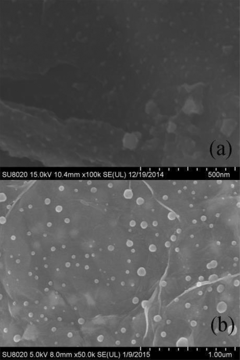
FE-SEM images of (a) GO/nano-S and (b) graphene/nano-S/PANI nanocomposite.
Fourier-transform infrared spectral analysis
Fourier-transform infrared (FTIR) spectra of GO, PANI and graphene/nano-S/PANI nanocomposite are shown in Figure 4. In the FTIR spectrum of pure GO, the peaks observed at 3393, 1730, 1630 and 1054 cm−1 correspond to –OH bending, C=O bending, aromatic C=C and C–O–C, respectively. 22 For pure PANI, the peaks at 1580, 1491, 1294 and 1181 cm−1 were attributed to the following vibrations, respectively: C=C stretching of the quinonold ring, benzenoid ring, the C–N stretching of secondary aromatic and C–H bending of benzenoid ring, indicating that aniline was polymerised by end-to-end connection. 23 Compared to FTIR spectra of individual GO and PANI, the C=O and C–O–C of the GO at 1730 and 1054 cm−1 completely disappeared in graphene/nano-S/PANI, which suggests that GO was reduced to graphene by aniline, in accordance with the above XRD results. Moreover, all the characteristic peaks of PANI appeared on the spectrum of graphene/nano-S/PANI nanocomposite, such as 1580, 1507, 1290 and 1180 cm−1. Based on these facts, we concluded that PANI chains were integrated with GO to form the graphene/nano-S/PANI nanocomposite.

FTIR spectra of GO, PANI and graphene/nano-S/PANI nanocomposite.
Raman spectral analysis
Raman spectroscopy is an effective method to investigate the structural properties of graphene-based materials. In Figure 5, the Raman spectra of GO and graphene/nano-S/PANI composite are shown. Among them, the two bands of D (1346 cm−1) and G (1553 cm−1) are the characteristic peaks attributed to the spectrum of graphene, representing D bands and G bands related to a series of defects caused by the breath of the sp2-rings of the graphene and the E2 g mode of sp2 carbon atoms, respectively. 24,25 The spectrum of graphene/nano-S/PANI shows a sequence of peaks situated at 518, 576, 818, 1179, 1250, 1457 and 1531 cm−1 attributed to the phenazine-like segment, out-of-plane C–H deformation of the quinonoid ring, C–H banding in the quinonoid ring, C–H bending deformation in the benzenoid ring, the C–N stretching mode of polaronic units and C=N stretching vibration of the quinonoid ring, respectively, revealing the presence of the doped PANI structure. 26,27 The comprehensive analysis of XRD, FE-SEM, energy-dispersive X-ray and FTIR spectra revealed that a ternary graphene/nano-S/PANI nanocomposite was successfully synthesised.

Raman spectra of GO and graphene/nano-S/PANI nanocomposite.
X-ray photoelectron spectroscopy pattern analysis
X-ray photoelectron spectroscopy (XPS; Figure 6) is employed to measure the elemental composition on the surface of graphene/nano-S/PANI composite. It is well known that the bands centred at 284.8 eV are consistent with C 1s. 28 The C 1s spectrum in Figure 6(a) was deconvoluted into four Gaussian peaks, centred on the values of the binding energies of C=C (283.4), C–C (284.7 eV), C–O (286.1 eV) and C=O (287.3 eV). 29 The S 2p spectrum of graphene/nano-S/PANI is composed of two peaks, located at the banding energy of 164.2 eV and 165.3 eV, attributed to S 2p3/2 and S 2p1/2 core levels (shown in Figure 6(b)). 30 Graphene/nano-S/PANI nanocomposite displays additional nitrogen groups due to the PANI coated on the surface of graphene/nano-S. Seen from the N 1s spectrum (Figure 6(c)), it is worth to note that the spectrum could be divided into three peaks, located at 398.7 eV, 399.8 eV and 400.7 eV, corresponding to quinonoid amine (=N–), benzenoid amine (–NH–) and nitrogen cationic radical (N+), respectively, indicating the presence of PANI in the composite. 31

XPS spectra of (a) the C 1s region, (b) the S 2p region and (c) the N 1s region of graphene/nano-S/PANI nanocomposite.
Electrochemical properties
The electrochemical performance of graphene/nano-S/PANI composite as an electrode material applied for supercapacitors was studied by CV and galvanostatic charge/discharge in a three-electrode system.
CV is considered to be an ideal technique to investigate the capacitive behaviour of electrode materials. 32 As shown in Figure 7(a) and (b), the shape of the CV curves clearly exhibit pseudocapacitive behaviour caused by electrochemical reactions in the potential intervals from −0.2 V to 0.8 V. In Figure 7(a), CV curves for composite electrode at various scan rates are shown. With an increase of scan rate from 5 mV s−1 to 100 mV s−1, the area of the CV curve increases. Figure 7(b) illustrates the CV curves of graphene/nano-S/PANI and pure PANI at the scan rate of 100 mV s−1. It can be seen that the closed cycle CV curve is proportional and the proportion of graphene/nano-S/PANI composite is much larger than that of pure PANI.
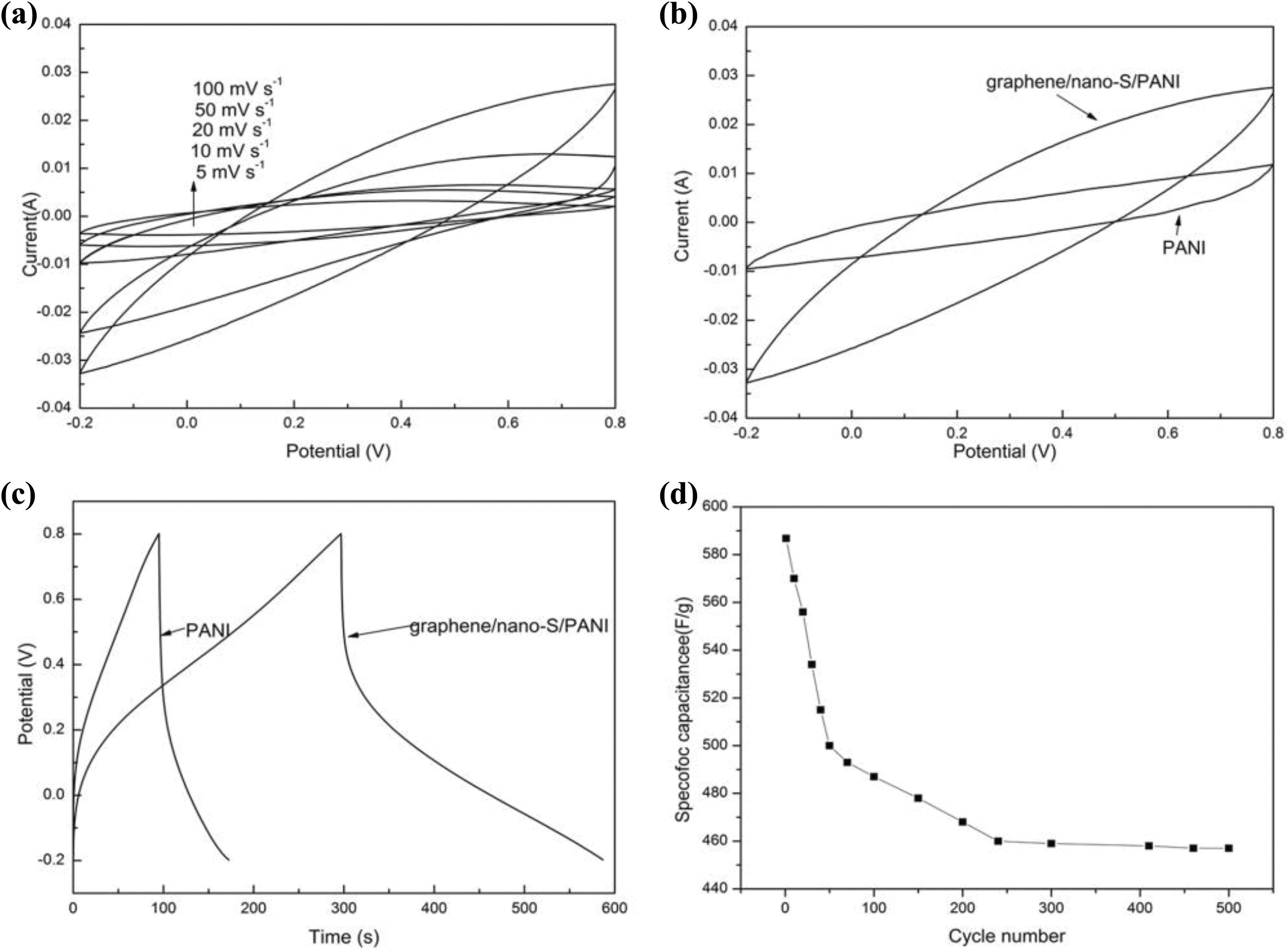
(a) Cyclic voltammograms of the graphene/nano-S/PANI electrode at different scan rates; (b) cyclic voltammograms of the graphene/nano-S/PANI electrode and PANI electrode at a scanning rate of 100 mV s−1; (c) galvanostatic charge/discharge curves of the graphene/nano-S/PANI and PANI electrode at a current density of 1 A g−1; and (d) cycle stability of the graphene/nano-S/PANI electrode at a current density of 1 A g−1.
The galvanostatic charge/discharge technique is a reliable method to estimate the electrochemical capacitance of supercapacitors. Figure 7(c) shows a typical galvanostatic charge/discharge curve of graphene/nano-S/PANI composites and PANI at current density of 1 A g−1. The specific capacitance of graphene/nano-S/PANI composite is 586.8 F g−1, which is higher than that of PANI (171 F g−1). It can be speculated that the introduction of graphene improves the electrode/electrolyte contact surface area for electronic or electrolyte ion transport, and the elemental S existence in graphene sheets also boosts the surface areas. Moreover, the charge/discharge curves show a deviation from the ideal triangle shape due to the contribution of pseudocapacitance, which is in agreement with the CV result. As shown in Figure 7(d), the capacitance retained about 77.9% (594.8 F g−1) of initial capacitance after 500 cycles. Compared with other S electrode materials, the graphene/nano-S/PANI ternary nanocomposite electrode exhibits high special capacitance and excellent cycling life, which can be attributed to the synergistic effect of each component included in the composite: graphene provided high area for S deposition and avoided the S to cohesion. Meanwhile, the graphene and PANI have excellent conductivity which is favourable for electronic conductive channels.
Conclusion
In summary, the graphene/nano-S/PANI ternary nanocomposite was successfully synthesised via a simple hydrothermal method. The structural characteristics and chemical composition of as-prepared materials were investigated by XRD, FE-SEM, FTIR, XPS and Raman spectroscopy. Owing to the specific combination of the advantages of graphene, nano-S and PANI, the composite exhibited outstanding electrochemical performance, showing a specific capacitance as high as 619 F g−1 at a scan rate of 5 mV s−1 and excellent electrochemical stability with capacitance retention of 77.9% (457 F g−1) of initial capacitance (586.8 F g−1) after 500 cycles at a current density of 1 A g−1. This facile and effective approach and encouraging electrochemical properties may play a vital role in the further promising application in supercapacitors.
Footnotes
Declaration of conflicting interests
The author(s) declared no potential conflicts of interest with respect to the research, authorship and/or publication of this article.
Funding
The author(s) disclosed receipt of the following financial support for the research, authorship and/or publication of this article: This work was supported by the Opening Project of CAS Key Laboratory of Materials for Energy Conversion.