
Abstract
Brush seal is a novel type contact seal, and it is well-known due to its excellent performance. However, there are many intrinsic drawbacks, such as hysteresis, which need to be solved. This article focused on modeling hysteresis in both numerical way and analytic way without pressure differential. The numerical simulation was solved by the finite element method. General contact method was used to model the inter-bristle contact, bristle–rotor contact, and bristle–backplate contact. Bristle deformation caused by both vertical and axial tip force was used to validate the numerical model together with reaction force. An analytic model in respect of the strain energy was created. The influence of structure parameters on the hysteresis ratio, with the emphasis on the derivation of hysteresis ratio formula for brush seals, was also presented. Both numerical model and analytic model presented that cant angle is the most influential factor. The aim of the article is to provide a useful theoretical and numerical method to analyze and predict the hysteresis. This work contributes the basis for future hysteresis investigation with pressure differential.
Introduction
Brush seals have been adopted in turbomachinery for around 30 years. A typical brush seal consists of a backplate, a front plate, and a pack of bristles, as shown in Figure 1. Advantages of brush seals, such as less leakage than labyrinth seals and accommodation of shaft excursions, are part of the reasons for brush seals being regarded as the substitutes for labyrinth seals. However, there are still some problems, such as hysteresis, which needs to be studied and solved.

Schematic diagram of brush seal geometry. The center figure shows the front view of brush seal-rotor system. The left figure shows the cross section View A-A. The right figure shows the parts in magnified brush seal.
Brush seal hysteresis is a friction dominated phenomenon. Wear, heat generation, and even material failure are caused by hysteresis. Investigation into hysteresis has been done by researchers all over the world. Stiffness check is a good method to evaluate hysteresis of brush seals. For most of the previous studies, force was measured directly without pressure differential while torque was measured with pressure differential. Crudgington et al. examined hysteresis by experiments. In their experiments, contact force and contact torque were obtained at working conditions with and without pressure differential, respectively. However, their experimental results did not match well with the theoretical results. 1 With the development of measurement technology, direct force measurement for brush seals, which are subjected to pressure differential, has been achieved. Aksoy and Aksit presented a brush seal stiffness measurement. In their measurements, pressure differential, rotor rotation, and radial movement were applied and contact force rather than torque was measured directly. 2 In addition, Bidkar et al. developed a fixture for measuring contact force directly for brush seals subjected to pressure differential, but the rotor rotation was not covered and the uncertainty was up to 30% in their experiments. 3 Additionally, the detailed geometry parameters were not introduced in neither Aksoy and Aksit’s 2 nor Bidkar et al.’s 3 studies. Zheng et al. analyzed a variable bristle diameter brush seal stiffness at a large pressure differential by experiments. Only one section of brush seal ring rather than the whole ring was used to evaluate stiffness. Part of their experimental results may not be ideal. 4 Neither contact force nor contact torque but leakage was characterized as a quantity to evaluate hysteresis by Basu et al. 5 Above all, experiment especially the direct reaction force measurement becomes gradually a popular method to evaluate hysteresis, but still needs to be improved.
Numerical simulation is another common way that has been adopted by many researchers to investigate brush seals. Evenly spaced staggered tube banks model, containing one or more rows of circles or beams, has been used in computational fluid dynamic (CFD), finite element method (FEM), and fluid–structure interaction (FSI). Kang et al. analyzed aerodynamic resistance and pressure distribution of brush seals by two-dimensional (2-D) tube bank model via CFD. 6,7 Sun et al. studied the leakage characteristics by three-dimensional (3-D) tube banks model and FSI. 8 Demiroglu et al. analyzed hysteresis and friction by both experiments and numerical simulations, and the pressure differential was not introduced. However, the comparison of numerical results and experimental results was presented only for the rotor-up process. In addition, there was a difference between two kinds of results. 9 Chen et al. analyzed hysteresis without pressure differential based on Demiroglu et al.’s 9 experiments. By bristle tip pressure, Chen et al. found that cant angle was the most influential factor in hysteresis. 10 Crudgington et al. developed a brush seal model containing full contact, pressure differential, and radial movement by ADINA. The pressure differential was derived from porous model and exerted on the bristle surface. The numerical model was validated by experimental results only for the case without pressure differential. 11 Duran et al. developed an FEM brush seal model to analyze the stiffness by ABAQUS. Their model was able to obtain the hysteresis loop in the static (without rotor rotation), dynamic (with rotation), and pressured cases. Inter-bristle contact and rotor–bristle contact were included in the model as well as the contact between bristles and backplate. Both beam element and solid element were used to compare the efficiency. They found that the beam element required less simulation time than solid element. Pressure-clearance tabular was used to define inter-bristle contact. But contact parameters such as clearance and contact pressure were not introduced in their study. Their model did work to some extents but was not flawless. Such as results from beam element numerical model matched poorly with the experimental results with pressure differential, especially for the rotor-down step. 12 –14
The analysis of bristle force behavior and deflection is for brush seal hysteresis study. However, pioneer studies regarding bristle deflection is in a lower level than other studies. Both large deformation beam theory and small deformation beam theory have been used in analyzing bristle deflection. Chen et al. presented the bristle force behavior in detail by small beam deformation theory. They introduced the line load exerted on the bristle surface and vertical force exerted on bristle tip. However, the axial load was not included in their research. 15 Axial load was not covered in the Demiroglu et al.’s research, either. 9 Stango et al. analyzed bristle deflection by large deformation beam theory, Runga–Kutta method, and Newton iteration method. Both vertical load and axial load were introduced in their research, but it was time-consuming for coding and hard to achieve for engineers. 16 Cicone and Pascovici presented a nonlinear model to determine bristle deformation. They also evaluated the small deformation beam models from published articles. The results shown that small deformation beam models are able to give a good approximation for medium or high compliant bristles. 17
According to the literature review above, it is hard to model the brush seal and validate models due to the following reasons. First, bristle is an elongated beam. Large deformation of bristles would lead to the dramatic change of stiffness matrix during the solving process. Second, contact is nonlinear. Inter-bristle contact, bristle–backplate contact, and bristle–rotor contact make the model complicated. Third, the uncertainty of reaction force experiments is obvious, which is inappropriate to validate numerical models.
The current analytic and numerical studies, which were based on the research by Demiroglu et al. 9 and Duran et al.12–14, enhance our understanding of hysteresis on the brush seal. Pressure differential was not included in this article, and it is open for future work. In the “Numerical model” section, the present numerical model was based on Duran et al.’s work.12–14 In the “Analytic model” section, strain energy was adopted to create a hysteresis model which could predict hysteresis without pressure differential. A quantity was proposed to evaluate hysteresis. The present research is the basis for the future hysteresis analysis with pressure differentials.
Experiment
Experimental procedure
The present research adopted Demiroglu et al.’s experiments 9 : Seal No. 8, Loading case 2. Geometry parameters are listed in Table 1. Pressure differential was not introduced in their studies. The hysteresis loop was presented in figure 15 in Demiroglu et al.’s article. 9 A matching shoe, with a diameter of 129.54 mm and a width of 12.7 mm, was used as a simplified rotor to contact bristles. The up and down movement of the shoe was used to push and retract the bristles. Free bristles, which did not contact the shoe, were pushed away from the test bristles which contacted the shoe, as shown in Figure 2. In this way, free bristles did not affect the deflection of the test bristles. Demiroglu et al. measured the reaction force between the bristles and the rotor by a load transducer. 9
Seal 8 geometry parameters.

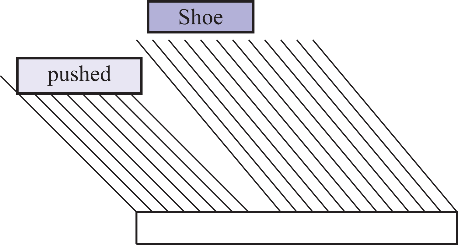
Schematic representation of bristles pushed away and bristles loaded by a shoe.
Single bristle force calculation
For numerical analysis, it is almost impossible to model a bristle pack in an FEM code. Generally, a typical brush seal numerical model contains 1–5 rows, 5–15 columns bristles. To make comparisons between the experimental results and the numerical results, experimental results should be transformed, since the reaction force measured in Demiroglu et al.’s experiments
9
was between the shoe and many bristles. The proportion of the bristles contacted the shoe, as shown in Figure 3, can be calculated as follows: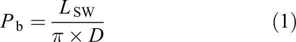

Schematic diagram of show width L SW and seal diameter D.
P
b is the ratio of the amount of bristles which contacts the shoe to the number of total bristles; L
SW is the shoe width; and D is the seal diameter. In Demiroglu et al.’s experiment,
9
L
SW is 12.7 mm. Therefore, 
where f
b is the single bristle reaction force,
Numerical model
Geometry model, element type, and boundary condition
Two different geometry models were adopted in the present research: Model A contains one backplate, one rotor, and five bristles. Five bristles are in one row, as shown in Figure 4(a) and (b). The gap between two bristles is one-tenth of the bristle diameter. Model B contains 1 backplate, 1 rotor, and 22 bristles. Twenty-two bristles are in three rows and a staggered arrangement, as shown in Figure 4(c) and (d). The gap between two bristles is one-tenth of the bristle diameter.

Schematic diagram of numerical geometry: (a) front view of model A; (b) side view of model A; (c) front view of model B; and (d) side view of model B.
The backplate and rotor were defined differently compared with them in Duran et al.’s models.12–14 In the previous models, both backplate and rotor were modeled as shell elements. Shell elements are adopted to model members numerically whose thickness is notably smaller than the rest dimensions. Shell-element members are two-sided. Since general contact detects contact pairs by algorithm rather than users, a warning occurred when general contact determined which side of a shell contacts bristles. Detailed description about general contact is presented below. The present research modeled both backplate and rotor as C3D8R solid elements with the thickness of 0.1 mm.
B31 element was used to model bristles. Compared with solid element, beam element requires less computational time and storage. As described in the work of Duran et al., 13 solid element simulations took 5–6 days while beam element simulations took less than 1 h. The output file size was 60 GB for solid element while 150 kB for beam element.
The boundary conditions in the present research were developed based on Duran et al.’s models.12–14 Six degrees of bristle freedoms were fixed at the top. The backplate was fixed totally as well. The rotor excursion was modeled by the rotor-up and down movement. In model B, the symmetry boundary condition was added to simulate the whole brush seal section.
Contact algorithm choice in ABAQUS/standard
When modeling contact in a numerical model, ABAQUS provides many methods such as contact pairs and general contact. Contact pairs method is the most popular in FEM codes. As shown in Figure 5(a), user must indicate which pairs of surfaces may interact with the others or which surfaces may interact with themselves. Each contact pair is assigned a contact formulation with an essential interaction property. It is highly efficient to define a contact problem which contains limited contact pairs. While in general contact, contact pair is detected by algorithm rather than user. Part A, Part B, Part C, and Part D are all defined as a single interaction assuming everything can hit everything. This definition is described in Figure 5(b). The boundary of the contact domain is delineated by a black rectangle. Inside the contact domain, Part A not only can contact Part B, Part C, and Part D but also can contact Part A itself. It is more competent to define many contact pairs in a model by general contact than defining contact pairs. It is remarkable that brush seal numerical model contains many contact pairs. Especially for inter-bristle contact, each bristle contacts at least nearby six bristles if bristles are in a staggered arrangement. Therefore, general contact was used to define contact in the present research.

Schematic diagram of defining contact in (a) contact pair. Each contact pair should be defined by user (b) general contact. Inside the black rectangular, each part can contact everything (including the part itself) without defining contact pairs.
Settings in ABAQUS/standard general contact
The present research adopted three contact formulations: (1) edge-to-edge contact, (2) vertex-to-surface contact, and (3) edge-to-surface contact. Inter-bristle contact can be regarded as edge-to-edge contact, as shown in Figure 6(a) and (b). Beam radius was activated by adopting related options in the ABAQUS input file since edge-to-edge contact is not supported in ABAQUS/CAE. Bristle–rotor contact was modeled by vertex-to-surface contact, as shown in Figure 6(c). Bristle–backplate contact was modeled by edge-to-surface contact, as depicted in Figure 6(d). Hard contact was adopted in the normal behavior, and penalty friction formulation with a frictional coefficient of

Schematic diagrams of three kinds of contact formulas. (a) and (b) Edge-to-edge contact; (c) vertex-to-surface contact; and (d) edge-to-surface contact. 18
Analytic model
The force behavior analysis
An analytic model was created in the present research to evaluate the hysteresis of a brush seal. Pressure differential was not introduced which was consistent with Demiroglu et al.’s experiments. 9
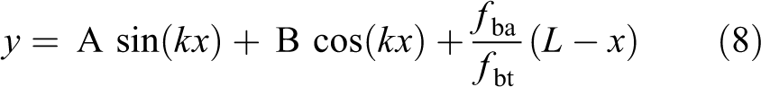
The force behavior of a single bristle is shown in Figure 7. Lines BA and BE are undeformed and deformed bristles, respectively. Lines CD and IK are the rotors. Line IK is the rotor’s original location and Line CD is the highest location for rotor lifting up. 

Schematic representation of a bristle force behavior. AB and IK represent the original position of bristle and rotor, respectively. BE and CD represent the displaced position of bristle and rotor, respectively.
where 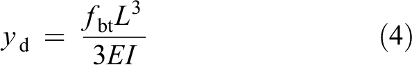
where yd
is the deformation at the free tip point and L is the free length of bristle. As for a typical bristle, the following relations between

However, the bristle is subjected to f bt and f ba simultaneously. The axial load, f ba, can cause buckling. In addition, the deformation is different when compared with that of a vertical concentrated loading f bt, as a result of f ba. The bristle is regarded as a column with one fixed end, B, and one free connected end, A. The elastic curve for the bristle is expressed as follows:

Equation (6) is linear, nonhomogeneous differential equation of the second order with constant coefficients. Transposing the term containing
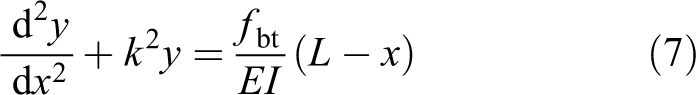
The general solution of equation (7)is:
The first partial derivative of
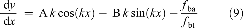
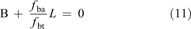
where A and B are unknown constants, and it can be obtained by solving equation (9) using the boundary conditions. The boundary conditions are expressed as follows:

Substituting equation (10) into equations (8) and (9), one can obtain:

Bristle strain energy
In solid mechanics, strain energy is a kind of energy stored in a member undergoing deformation. The strain energy is defined as the increase in energy associated with the deformation of the member and is equal to the work done by a slowly increasing load applied to the member. The load

where

Equation (14) was adopted to calculate the strain energy of a bristle. The bending moment, M(x), is at the point with the distance x from the fixed point. The strain energy for a bristle can be expressed as follows:

The hysteresis model based on energy method
The present research characterizes the brush seal hysteresis by work. A bristle–rotor system is assumed here. During the rotor going up, the input work on the system is done by the rotor. The energy, transformed by input work, divides into two parts: One is the strain energy of the bristles and the other one is counteracted by the frictional force. The strain energy of the bristles is stored inside the system. During the rotor going down, the deformed bristles recover to its original shape and the energy inside the bristles decreases to zero again. Part of the stored energy is counteracted by the friction.
A frictional force is triggered by the contact between the rotor and the bristle. It is assumed that the classical isotropic Coulomb friction model is applicable:


where
Hysteresis can be characterized by the ratio of frictional work to input work. The analytic hysteresis ratio, R
ha, is written as: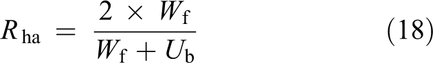
where 2 × W f is the frictional work during the rotor-up and down process. W f + Ub is the input work by rotor.
Results and analysis
Both models A and B were adopted to perform simulation in the present research. Single bristle reaction force
Model verification
The present research validates numerical model in two ways. Figure 8 shows the comparison of bristle deformation between the numerical results and analytic results of equation (8). Both the green line and the blue line are the deformed neutral axis of bristles. For the bristle length-labelled axis, 0 is the bristle fixed end and 12 is the bristle free tip. It is found that two kinds of results match well with each other but a slight difference occurred approaching the free tip of bristle. The error is approximately

The comparison of bristle deformation between the numerical results and analytic results.
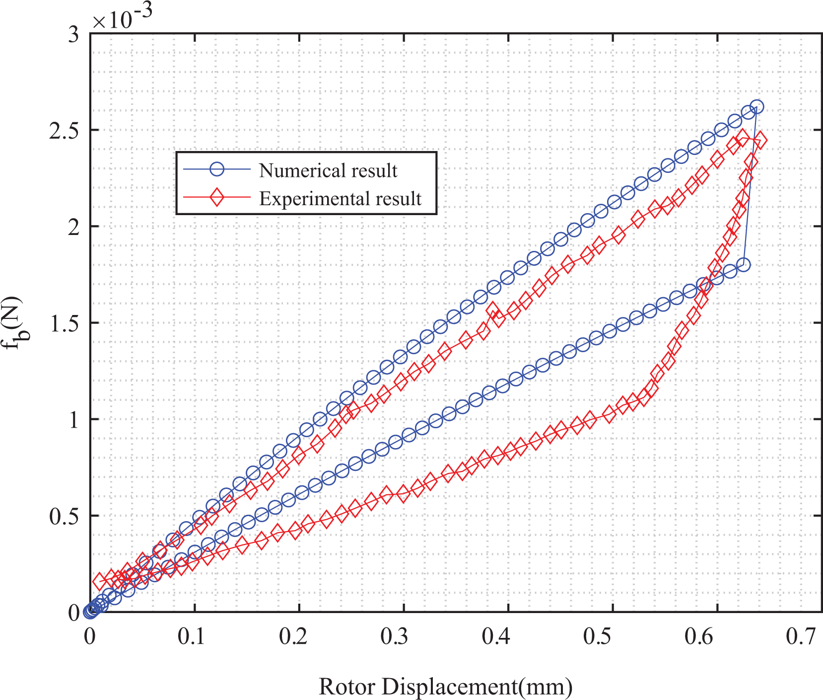
The comparison of bristle–rotor reaction force between the numerical results and experimental results.
Numerical hysteresis model of brush seal
As mentioned above, hysteresis can be characterized by work. Therefore, hysteresis can be assessed by force and displacement. Figure 10 shows the displacement and 

Hysteresis area (area A) and input work (the sum of areas A and B) from numerical results.
The influence of geometry parameters on hysteresis
Stiffness is used to measure an elastic member’s resistance to deflection or deformation by an applied force. Bristle radial stiffness is expressed as:
where
Geometry parameters of numerical models.

The influence of bristle length and diameter on hysteresis
Figure 11 shows the effect of bristle length and diameter on hysteresis ratio. The cant angle is 45° for the five cases. The diameter and length are changed based on equations (5) and (20). One can find that both R
ha and R
hn vary insignificantly. R
ha varies from

The comparison between R ha and R hn of five different models with the same bristle cant angle.
The influence of bristle length and cant angle on hysteresis
Figure 12 demonstrates the influence of bristle length and cant angle on hysteresis. The bristle diameter keeps unchanged, 0.102 mm, for these five cases. Rest two parameters are changed based on equations (5) and (20). Both R
ha and R
hn decrease with the increment of cant angle (increasing cant angle accompanies the decrease of bristle length). R
ha decreases from

The comparison between R ha and R hn of five different models with the same bristle diameter.
The influence of bristle diameter and cant angle on hysteresis
Figure 13 illustrates the impact of bristle diameter and cant angle on hysteresis. The bristle length keeps constant, 12 mm, for geometry no. 10, 11, 2, 12, and 13. The hysteresis ratio trend of these five cases is similar to that of geometry no. 6, 7, 2, 8, and 9. Hysteresis becomes weak when the cant angle is larger. R
ha decreases from

The comparison between R ha and R hn of five different models with the same bristle length.
Conclusion and future work
The hysteresis of brush seals without pressure differential was discussed in the present article. Two different geometric models were adopted to simulate the brush seal hysteresis. General contact was introduced in the numerical model. The bristle force behavior was analyzed. The method for quantifying hysteresis characteristics, based on the strain energy and the energy method, was proposed. The influence of geometric parameters on hysteresis was also studied. The conclusions can be summarized as follows. Without pressure differential, two different geometric models work the same as each other in analyzing brush seal hysteresis. Numerical bristle deformation matches well with the analytic bristle deformation but with somewhat error. Both the analytic hysteresis ratio and the numerical hysteresis ratio can indicate that bristle cant angle is the most influential factor among three geometry parameters: bristle length, cant angle, and bristle diameter. Hysteresis accounts for from
Future work could be commenced both in an analytic way and in a numerical way with the pressure differential introduced. For the numerical model, pressure differential exerted on the bristle surface can be converted to line load along the neural axis of a bristle. Preliminary investigation is promising but time-consuming. Numerical results of the single bristle force f b from models A and B were different. Detailed parameter trial and error will be implemented in the future.
Footnotes
Declaration of conflicting interests
The author(s) declared no potential conflicts of interest with respect to the research, authorship, and/or publication of this article.
Funding
The author(s) disclosed receipt of the following financial support for the research, authorship, and/or publication of this article: This work was supported by China Scholarship Council (grant no. 201608740003) and the National Natural Science Foundation of China (grant no. 51765024).