
Abstract
The influence of different tire skeleton structural parameters on tire grounding characteristics was investigated. Using a 225/60R18 100H radial tire as the research object, the experiment and simulation were carried out by changing the diameter of the belt steel wire, the angle of the belt layer, and the number of carcass plies. Using the model parameters obtained from the rubber physical test, the finite element model of the tire was created in Abaqus for static loading simulations, the relevant data such as tire pattern impression and sinkage were analyzed, and the validity of the model was investigated. The influence of skeleton material on tire structure was deduced by determining the amount of stored strain energy of tire. The results showed that the belt angle in the grounding area had the greatest influence on the belt stress and presented a second-order change. However, the number of carcass cord layers and the diameter of the belt steel wire had little effect on the corresponding skeleton stress. The number of carcass layers had the greatest influence on the stored strain energy of the tires. The diameter of the bundled steel wire and the angle of the bundle had little influence.
Introduction
Rubber tire can store more strain energy than other materials due to its unique super elastic material. This material plays an important role in reducing vehicle vibration and enhancing vehicle life. 1 With the development of computer technology, the application of finite element analysis in tire research is becoming increasingly extensive. Rugsaj and Suvanjumrat 2 and Kucewicz et al. 3 used finite element technology to analyze the force of non-inflatable tires under rolling and radial grounding conditions. Baranowski et al. 4 studied the damage of shock wave to tires by using finite element technology, so as to improve the explosion-proof performance of tires. Tian et al.5,6 studied the radial tire cord stress in the dynamic state. Sun et al. 7 and Liu and Gao 8 researched tire vibration characteristics of high-speed standing wave cord force and tread mode of the radial tire load, respectively. Phromjan and Suvanjumrat 9 and Ge et al. 10 used finite element analysis to investigate tire material characteristics and tire dynamic performance. Zhou et al. 11 and Liang et al. 12 respectively studied tire steering mechanics and strain energy density and fatigue analysis of radial tires in the static state. These scholars used the finite element method to study structure and mechanics performance of tires to some extent but did not further analyze tires strain energy to predict the tire’s resistance to deformation. In this study, the finite element model of 225/60R18 100H radial tire was established in the finite element software Abaqus 6.14 based on the model parameters obtained from the tire material characteristics test. Experiments and simulations were conducted by changing the diameter of the belt wire, the angle of the belt layer, and the number of cord layers of the tire body. The force variation of the tire tread, belt layer, and cord layer in the docking area of the tires were analyzed. The influence of skeleton parameters on tire structure was inferred by using the change of stored strain energy of tire.
Tire material property test
Rubber material test
A uniaxial tensile test was conducted on the rubber material of each part of a 225/60R18 100H radial tire, as shown in Figure 1(a). The rubber samples were processed into dumbbell shapes according to the standard GB/T-528, as shown in Figure 1(b).

Rubber specimen tensile process and rubber specimen: (a) specimen tensile process and (b) rubber sample.
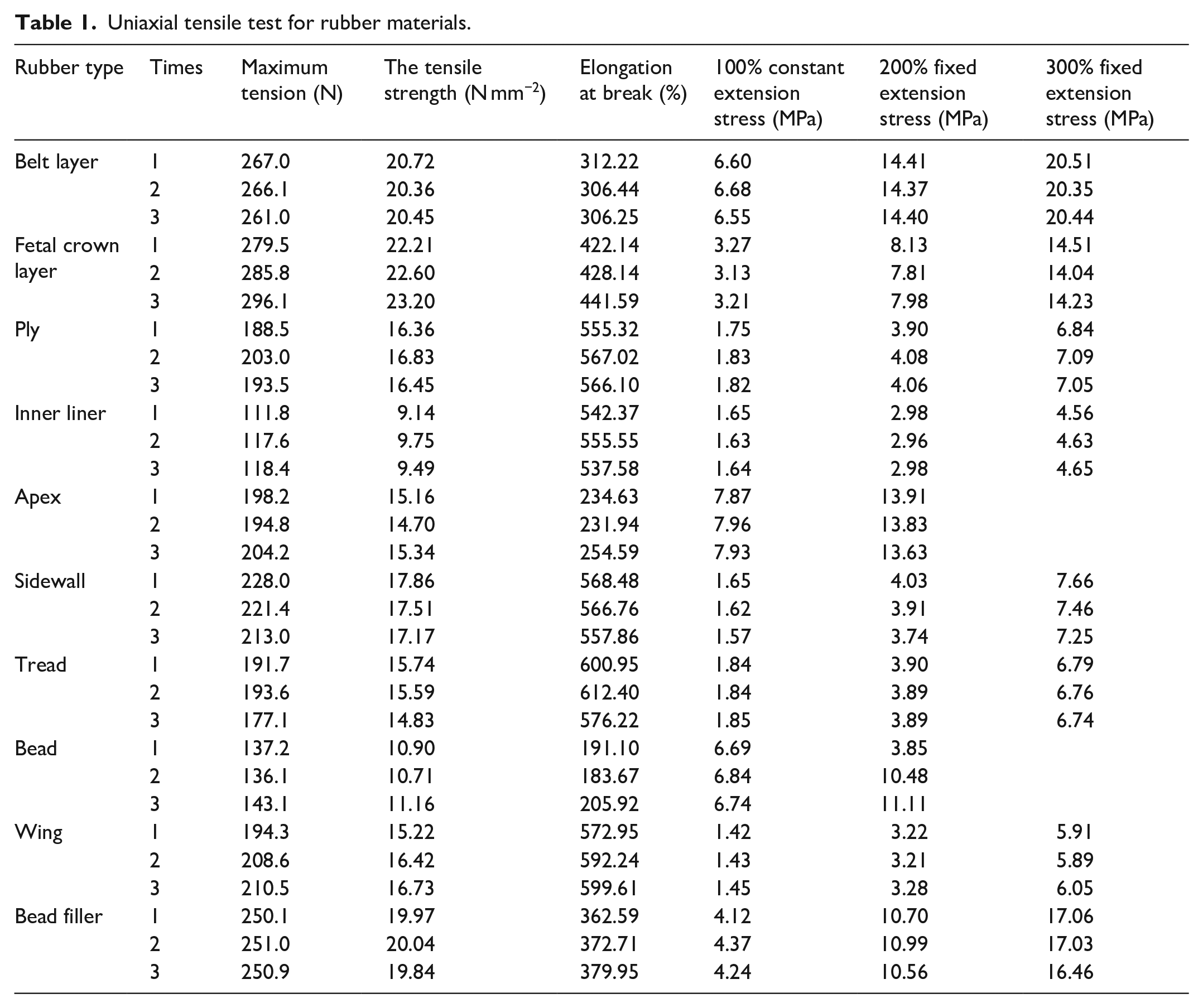
The tensile tests were performed on tread rubber, side rubber, triangle rubber, inner lining rubber, child mouth rubber, body rubber, crown band rubber, belt layer rubber, wing rubber, and bead rubber. The properties of the 10 samples measured in the test are shown in Table 1.
Uniaxial tensile test for rubber materials.
The stress-strain curves of 10 materials were plotted as shown in Figure 2. The abscissa in the figure is the material elongation, and the ordinate is the stress value. By comparison, it is found that the curve distribution of other compounds is relatively concentrated, except for a little large offset of Inner liner.
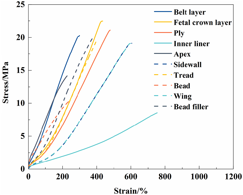
Rubber stress-strain curve.
Tire rubber is a super elastic material with complex mechanical properties. In the process of testing, the rubber material showed a non-linear stress distribution, and its behavior changed significantly. 13 Therefore, it cannot be treated as linear material alone. It is necessary to select a nonlinear and large deformation constitutive model to express it. In this paper, the main deformation is concentrated in the tread grounding area, so the tread rubber is taken as the basis for selecting the constitutive model. As shown in Figure 3, the Tread of rubber was fitted with three constitutive models: Neo Hookean, 14 Mooney Rivlin, 15 and Yeoh. 16 It was found that the Yeoh model had the best fitting effect. Finally, this constitutive model was selected to characterize the mechanical properties of the rubber materials in this study. The fitting parameters of the Yeoh model for the 10 types of rubber are shown in Table 2.
Yeoh model parameters of different rubber materials.


Constitutive model fitting.
Skeleton material characteristic test
The skeleton material was composed of filled rubber and cord, including steel cord and nylon cord. The mechanical test of the tire skeleton material was carried out as shown in Figure 4.

Photographs of tire skeleton material test: (a) wire extraction, (b) cord breakage, and (c) cord withdrawal.
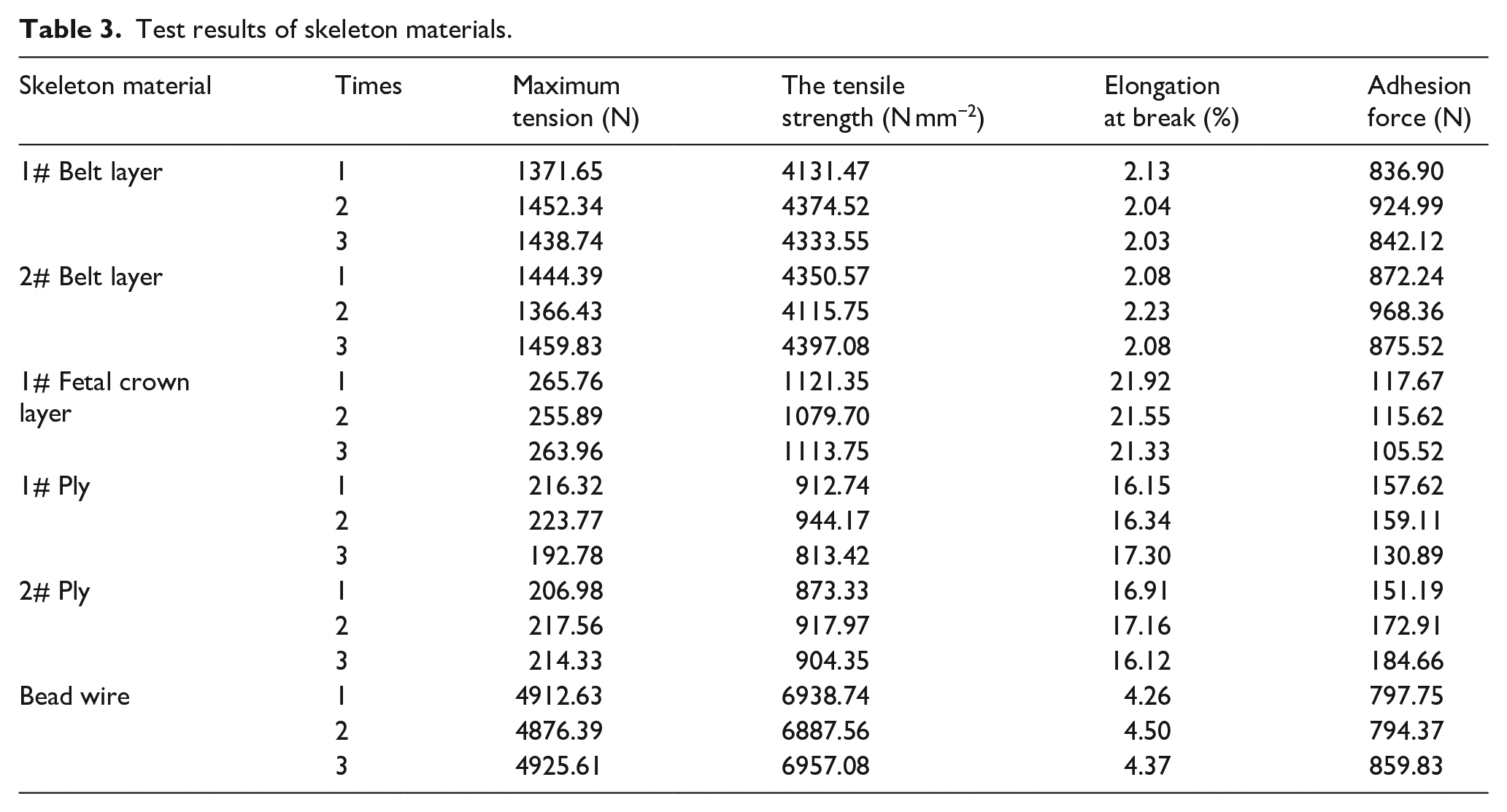
The maximum tensile force and elongation at break of the material can be obtained through the tensile test of the skeleton material. The adhesive force of the material can be obtained through the extraction test of the skeleton material. The relevant parameters of rubber cord measured in the test are shown in Table 3. The Yeoh model fitting parameters of the rubber-cord composite are shown in Table 4.
Test results of skeleton materials.
Skeleton material parameters.

Establishment of tire finite element model
Tire modeling
Used the tire 225/60R18 100H section to divide the tire tread into five grounding areas A, B, C, D, and E, as shown in Figure 5(a). The tire pattern and surface structure were simplified 17 by drawing the two-dimensional (2D) section in AutoCAD. The section was then segmented according to the rubber distribution. As shown in Figure 5(b), the tire can be roughly divided into belt ply, cord ply, tread, triangular rubber, bead, and other relevant parts. The material properties were defined in Abaqus and meshed. The skeleton material was embedded into the tire through the * embedded command. This method has similar effect with truss (cable) elements modeling. 18 The model established by this method also has the advantage of transmitting only axial force and that the rubber and cord grids do not have to coincide. But the difference is that this method is relatively simple and can reduce the amount of calculation to a certain extent.
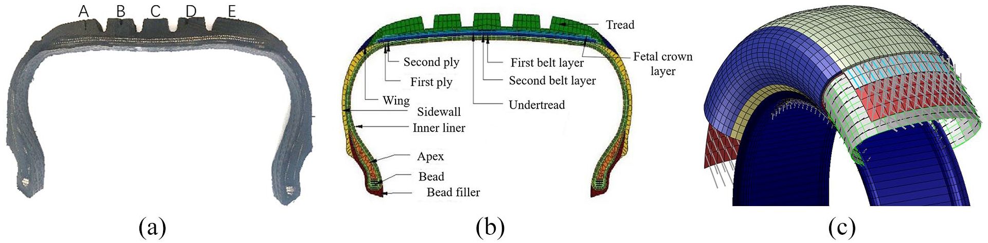
Two-dimensional schematic of tire section meshing and skeleton layer stacking: (a) section of tire, (b) section meshing, and (c) skeleton layer sectional view.
The tire body was divided into two parts: smooth tire and tread. The smooth tire was rotated 360° around the 2D section using the *SMG command to form a complete smooth tire model. The shape optimization command in Abaqus software is used to smooth the tire skeleton layer mesh. This step can effectively reduce the stress at the mesh transition and improve the accuracy of the stress on the skeleton fiber in the simulation process. The embedding and stacking mode of skeleton layer and smooth tire are shown in Figure 5(c). The tire tread was drawn by using UG three-dimensional software and IGS to import the file into Abaqus. As shown in Figure 6, the tread block and smooth tire were each meshed, and then the tread block was assembled on the smooth tire using the *tie command to assemble the model tire. The tire model had 75,120 units in total, including 48,000 rubber units and 27,120 reinforcement reinforcement units. At this time, the element type of rubber material was C3D8RH three-dimensional element, and the reinforcement element type was SFM3D4R surface element.

Tire pattern assembly process.
The contact analysis between the tire and the ground is shown in Figure 7.

Tire finite element model and grounding test: (a) tire grounding test and (b) finite element model.
Finite element model validation
Under a tire pressure of 0.25 MPa and a fixed load of 8 kN, a five-gang testing machine was used for the grounding test. The tire grounding stress was measured by the sensor under the bearing platform of the five rigid tester, as shown in Figure 7(a). The simulated tire pressure was realized by applying 0.25 MPa local pressure inside the tire. Then fixed the tire and applied a radial force of 8 kN to the ground in reverse to complete the simulation process, as shown in Figure 7(b). As shown in Table 5, tires with different skeleton material parameters were divided into five types (T1–T5). The stress pairs in the grounding region of the test and simulation are shown in Table 6.
Tire test parameters.

Comparison of test and simulation results.

Through the analysis, it was found that under the condition of constant tire pressure and load, changing the diameter of the belt steel wire, the angle of the belt layer, and the number of carcass cord layers, the change trend of the test value and simulation value was the same. The percent error between the test value and simulation value of the average ground stress was within 10%. The large strain in the grounding area was mainly distributed on both sides of the tire. As shown in Table 6, the pressure in the grounding areas A, B, C, D, and E of the same type of tires with different parameters fluctuates, but the fluctuation error is within the allowable range. The finite element model ensures the reliability of the force analysis on the inner cord of the tire and the stored strain energy.
Test and simulation analysis of tire grounding mechanical characteristics
Tire ground stress analysis
The tire grounding mechanical characteristic test was carried out by changing the diameter of the belt steel wire (T1 and T5), belt layer angle (T1, T3, and T4), and the number of carcass layers (T1 and T2). The test and simulation results are shown in Figure 8.

Stress cloud test and simulation comparison of different skeleton parameters.
Through the analysis, it was found that the ground stress of the tires with the five different structural parameters was distributed in five areas in an axisymmetric manner, concentrated in areas A, C, and E. However, there was an uneven distribution of tread rubber and tread pattern, and the test and simulation ground stress results were not completely within an acceptable corresponding range. In addition, the depicted color of the groove gap was dark, which shows that the stress of the pattern block extends outward from its center, and that the stress value at the gap was the smallest. Compared with the relevant parameters in Table 5, when the load remained unchanged, the radial stiffness of the tire increased with the increase in tire cord layers, and the tire sinking decreased by 2.9%. When the diameter of the belted wire was increased, the radial sink of the tire decreased by 0.6%. The diameter of the tire belt steel wire had little effect on the change of the radial stiffness of the tire. The belt angle increased from 61° to 63°, and the tire sinkage increased by 6.6%. However, when the angle increased to 67°, the sinkage decreased by 1.2%. The tire radial stiffness decreased first and then increased with the increase of belt angle.
Stress analysis of skeleton material in grounding area
Because the skeleton material is located on the inside of the tire, the stress of each part was difficult to measure in the test. The tire belt is the main skeleton material, making its stress the most obvious. Therefore, the finite element model was adopted to predict the stress condition of the skeleton material. To ensure the consistency of variables, the first belt layer and the first ply were selected for analysis. By changing the diameter of the belt steel wire, the angle of the belt layer, and the number of carcass plies, the monitored stress changes of the first belt layer and the first carcass ply were observed (Figure 9).

Rebar force comparison diagram of tire skeleton material along a transverse path: (a) T1 and T2 belt layer stress, (b) T1 and T2 ply stress, (c) T1 and T5 belt layer stress, (d) T1 and T5 ply stress, (e) T1, T3, and T4 belt layer stress, and (f) T1, T3, and T4 ply stress.
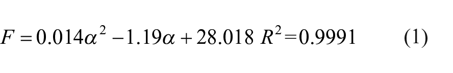
As shown in Figure 9(c) and (d), when the diameter of the belt steel wire was changed from 0.6 to 0.65 mm, the maximum force of the belt layer was maintained at 9 N, and the maximum force of the ply was distributed at the shoulder and maintained at 30 N. With the increase of the diameter of the belt steel wire, the force of the belt layer increased by 3.5%, and the force of the ply increased by 0.1%. As shown in Figure 9(a) and (b), when the diameter and angle of the belted steel wire were determined, if the number of cord layers was increased, the force of the cord layers at the shoulder position were reduced by 20%. Single-ply cord bore most of the force when the tire was compressed. Under the same working conditions, the force borne by double-ply cord was small. This shows that the double-layer curtain cloth can increase the radial stiffness of the tire and increase the service life of the tire. As shown in Figure 9(e) and (f), the force on the belt increased with the increase of the belt angle. When the belt angle increased from 61° to 63°, the force on the belt in the grounding area increased by 20%. When the angle increased to 67°, the force on the tire grounding area reached a maximum, and the force reached 12 N. Meanwhile, the change of the belt angle had little effect on the force of the carcass cord. The analysis shows that the force is obvious when the belt angle changes, while the change of the diameter of the belt steel wire and the number of plies have little effect on the force of the belt. For example, using T2 tire as the basic model and only changing the belt angle for the simulation, the X = 100 mm node was selected. Then we used the cftool toolkit for data fitting in MATLAB.
As shown in Figure 10, the error R2 is small when the first-order function is used to fit the change of cord angle and force, but when the third-order function is used to fit α, the coefficient of 3 tends toward 0, and the quadratic function is selected to fit it. The force of the cord and the angle of the cord show a second-order change, and R2 = 0.9991 has a good fitting degree, as shown in equation (1):

Force angle fitting of the belt layer.
Simulation analysis of tire stored strain energy
Tire is made of high elastic rubber material, vulcanized by different processes. In a common living environment, the shape variable of the tire inflation process is small, and the tire itself will store strain energy under the action of external forces due to the particularity of rubber material. In the constant temperature environment, the increase of energy in the tire system is equal to the work done by the external force on the tire, as shown in equation (2):

Where, F is the external force acting on the tire, ∆S is the deformation distance of the tire under the external force, and ∆W is the added energy in the tire system.
As shown in Figure 11, the tire loading process is divided into three analysis steps, and each analysis part is set to 1 s. Step1 is the tire inflation process, and the inflation pressure increases linearly with time. Step2 is the process of pre tightening the rims, and the rims on both sides are uniformly moved to the tire center by 12 mm. Step3 is the loading process of tire radial force, and the radial force increases linearly with time. The changes in the stored strain energy of various types of tires are shown in Figure 12.

Schematic diagram of tire loading at various stages.

Comparison of stored strain energy of the five different types of tires.
Through an analysis of Figure 12, it was found that the stored strain energy of the tires changed only 0.01% by changing the diameter of the belt steel wire and the angle of the belt layer. However, the number of carcass plies had a great influence on the stored strain energy. With the increase of ply number, the stored strain energy of the tires decreased by 3.3%. After inflation, the stored strain energy reached 120 kJ, and the stored strain energy under load condition increased by 10 kJ. In the same time range, the change of tire structural parameters did not affect the change trend of stored strain energy. When the inflation was completed and the load was applied, the stored strain energy changed suddenly. With the increase of the load, the stored strain energy increased slowly and decreased slightly within 2–2.5 s. The final stored strain energy of the whole model reached 130 kJ. At the moment of applying load, the sudden change of external force led to the sudden change of tire stored strain energy, which led to a slight decrease in a short time after loading. When the number of tire layers was increased, the tire structure was stable and the stiffness increased, and the intermolecular deformation of tire rubber decreased. This intermolecular deformation leads to significant energy changes in the tire system.
Conclusions
We established a finite element model of a 225/60R18 100H tire and performed a simulation analysis of the tire grounding mechanical characteristics and stored strain energy for skeleton materials with different parameters. By analyzing the stored strain energy of tire, the structural properties of tire can be inferred. The main conclusions are as follows:
(1) Changing the structural parameters of the tire skeleton has an impact on tire stiffness of 0.6%‒6.6%, and among the parameter changes, the change of belt angle has the greatest impact on tire stiffness. When the belt angle changes from small to large, the force on the ply in the grounding area is scarcely affected, while the force on the belt changes in the second order with the angle, and the stress concentration occurs in the belt at the grounding center.
(2) When the number of carcass layers is increased, the stress variation trend of the tire belt layer remains the same. The force in the grounding area fluctuates slightly with the increase of the number of carcass layers, but the force in the tire shoulder and sidewall decreases by 20% with the increase of the number of carcass layers. This shows that increasing the number of plies is conducive to enhancing the tire shoulder strength.
(3) During the process of tire inflation and loading, the stored strain energy of the tire changes suddenly, and the growth trend slows after the change. The change of the diameter of the belt steel wire and the change in angle of the belt layer have little effect on the stored strain energy of the tire, while the storage strain energy of the tire was affected by 3.3% by the number of cord layers. The strain energy decreases when the number of cord layers increases. This shows that the number of plies plays a key role in tire resistance to radial deformation, and also reflects the feasibility of using strain energy to check tire structure.
Footnotes
Authors’ Note
Shuiting Zhou, Luwen Chen, Yue Li, Pengfei Sun, Guoyun Su and Junling Meng are also affiliated to Fujian Provincial Key Laboratory of Advanced Design and Manufacturing for Passenger Cars, Xiamen, China.
Declaration of conflicting interests
The author(s) declared no potential conflicts of interest with respect to the research, authorship, and/or publication of this article.
Funding
The author(s) disclosed receipt of the following financial support for the research, authorship, and/or publication of this article: Supported by Natural Science Foundation of Fujian Province (No. 2020J01276), and Science and Technology Research Project of Xiamen University of Technology (No. YKJ22013R, No. XPDKT20026).