
Abstract
In this paper, a new analytical solution is presented to predict the interfacial stresses of a functionally graded beam reinforced by a prestressed CFRP plate under thermo-mechanical load. A finite element (FE) analysis is also employed to validate the results of the analytical solution, the results from both models agreed very closely. Also, a parametric study is carried out in order to identify the effects of various material and geometrical properties on the magnitude of interfacial stresses. The presented results show that the interfacial stresses are highly concentrated at the end of the laminate, which can lead to a debonding at this location. Also, the material and geometrical properties have a significant impact on the magnitude of interfacial stresses. This new research approaches the practical reality of the structures in their environment by taking into consideration a combination of neglected terms by the other studies. Therefore, the results presented in this paper can serve as a benchmark for future analyses of functionally graded beams strengthened by prestressed Carbon fibre-rein-forced polymer (CFRP) plates and improve the rehabilitation, mechanical and corrosion resistance.
Keywords
Introduction
Composite materials are widely used in many fields of structural applications during the last years, due to their strength-to-weight ratio and high durability, fatigue strength, minimal change of cross-section dimensions and corrosion resistance. One of the structural applications for composite materials is the rehabilitation of the ageing structures presenting defects of shape, corrosion effect and resistance losses. It can be accomplished by bonding carbon fibre-reinforced polymer (CFRP) composite plate to its soffit. This technique has been success-fully used for repairing metallic aircraft structures for a number of years using advanced fibre composites [1]. Also, it has been widely used in civil engineering to repair or upgrade reinforced beams. In other applications, several laboratory tests [2, 3] and field applications on bridges and other structures [4, 5] have been conducted using prestressed laminates. It has been found that prestressing the laminate helps in carrying a portion of the dead load, reduces or closes existing cracks in concrete structures, as well as improving the fatigue resistance of steel beams. The advantage of composite materials, generally constituted of FRP layers, is their high stiffness and their high resistance to the applied loads comparing to the conventional materials. However, they cause a discontinuity of properties and stress at the interfaces, which causes high concentrations of stresses, cracking of the matrix and a delamination at the edge of strengthening zone [6]. In order to correct these disadvantages, researchers developed a new class of heterogeneous composite materials. In 1984, the concept of functionally graded materials (FGM) was initially cited in Japan by a team of scientists specialized in materials, while preparing for a space plane project [7]. Due to the continuous and smooth variation of the constituent materials volume fraction (Usually metal and ceramic), FGMs are today used in most industrial applications and engineering structural designs such as: Nuclear, biomechanical, aerospace, automotive, shipbuilding, electronic and mechanical industries [8].
However, for reinforced structures (Homogenous and non-homogenous beams), debonding of the soffit plate from the beam is an important failure mode, it depends mainly on the interfacial shear and normal stresses between the beam and the bonded plate. Therefore, it is crucial to be able to predict the debonding failure load.
In this context, many studies have been conducted in order to predict the interfacial stresses either analytically, numerically or both. For example: Smith and Teng [9], Maleej and Bian [10], Deng et al. [11], Yang and Wu [12], Cai et al. [13], Tounsi and Benyoucef [14] and Tounsi et al. [15]. The problem of interfacial stresses when using prestressed laminates was treated by other researchers such as Al-Emmrani and Kliger [16] where they developed an analytical solution to determine the interfacial shear stress of an unloaded beam, Benachour et al. [17] where they provided a solution to predict the interfacial stresses of a simply supported beam with a bonded prestressed fibre-reinforced polymer (FRP) plate including the variation of fibre orientation in the FRP plate, however, it did not consider the effects of bending and thermal deformation in the plate and shear deformations model in the beam, Ghafoori and Motavalli [18] where they provided analytical solutions and experimental results to predict the behavior of reinforced beams with pre-stressed and non-prestressed FRP plates under three different load cases only.
Other researchers conducted their studies on the behavior of FGMs (Static and dynamic) such as San-kar [19] where the author developed an elasticity solution for bending of functionally graded beams (FGM beams) based on Euler-Bernoulli beam theory, Zenkour [20] where the author presented the static response for a simply supported functionally graded rectangular plate subjected to a transverse uniform load. However, only few studies aim at the prediction of the interfacial stresses in plated FGM beams with parameters included in this original research.
The objective of this original work is to present an analytical model to predict the interfacial shear and normal stresses of a functionally graded beam reinforced by a prestressed CFRP plate and subjected to a thermo-mechanical load. The obtained results are then compared with the FE analysis results using the ANSYS software. The material properties of the functionally graded beam are assumed to vary continuously through the thickness of the beam, according to the power distribution law. Finally, a parametric study was carried out in order to identify the effects of various material and geometrical properties on the magnitude of interfacial stresses and positively affect the reinforcement of structure.
This new research takes in consideration a combination of neglected terms by the other studies, approaching the practical reality of the structures in their environment. Therefore, the results presented in this paper can serve as a reference for future analyses of similar cases that include functionally graded beams strengthened by prestressed CFRP plate and subjected to a combination of mechanical and thermal loads.
Basic Assumptions
For this study, a simply supported FGM beam with a span of L and subjected to a uniformly distributed load is considered. A plate with a length of Lp anda thickness of tpis symmetrically bonded to its soffit. Its width is the same as that of the FGM beam. The thickness of the adhesive layer is ta. The FGM beam section area is b ×h. (Fig. 1)

Soffit-Plated FGM Beam.
The main assumptions used in this research are as follows:
All materials including, the FGM beam, plate and the adhesive layer are linear and elastic solids;
The adhesive–FGM beam interface and at the adhesive–plate interface are perfectly bonded (There are no slips at the interface of the bond)
The shear and the normal stresses in the adhesive layer do not vary through the thickness of the adhesive.
Shear deformations in the plate and FGM beam are neglected.
Bending deformations of the adhesive are neglected.
The shear stress analysis assumes that the curvatures in the beam and plate are equal (Since this allows the shear stress and normal stress equations to be uncoupled). However, this assumption is not made in the normal stress solution.
The material properties of the FG beam vary continuously through the thickness of the beam, according to the power distribution law.
In this study, the FG beams elastic modulus is assumed to vary continuously across the beam thickness according to a power law function (P-FGM) [21, 22] given by Equation 1.

Em: Young modulus of the bottom surface of the FG beam (Metal).
Ec: Young modulus of the top surface of the FG beam (Ceramic).
n: The power-law index. The distribution of Young's modulus E(y) of the beam thickness is illustrated in Fig. 2. According to the study of Jin and Batra [23]. the effect of the beams Poisson's coefficient variation on the deformations is minimal. Therefore, the FG beams Poisson's coefficient is supposed constant.

Variation of Young's Modulus According to the Beam Thickness.
In this paper, the Euler-Bernouli beam theory (EBT) is considered. Therefore, plane sections normal to the beam axis are assumed to remain plane and normal after deformation. Also, we assume that there is no thickness change which means that w displacements are independent of z. Therefore, the displacement can be written as:

Where u0 and w0 denote the middle surface displacement components along the x and z directions respectively. Within the framework of small perturbations hypothesis, the linear Green-Lagrange strain tensor writes:

Then the strain component in equation (3) is related to its corresponding stress component through the basic constitutive law:

In the Euler-Bernoulli beam theory, the axial force N and bending moment resultants M are defined as:

By substituting ox from equations (3) and (4) into equation (5), a relation between the force and moment resultants and the beam deformations can be derived as follows in equation (6):

The expressions of the beam stiffness coefficients A, B and D are:

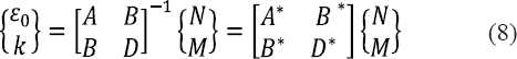
The inverse relations corresponding to that in equation (6) are:
Since the axial force resultant N = 0, the expressions of the deformations are written as:

By substituting the above equations in (3) and (4), the axial stresses in a FGM beam take the form in equation (10):

The expression of the neutral axis is given from equation (10) as follow:

Fig.3 represents the forces in an infinitesimal element of a soffit-plated FGM beam, from which the shear stress τa in the adhesive layer at any section x is given by equation (12):

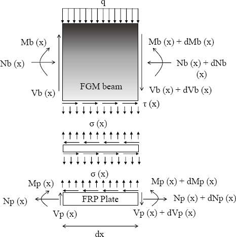
Forces in Infinitesimal Element of a Soffit-Plated FGM Beam.
Where Ga, ta, up, ub denote the shear modulus, the thickness of the adhesive, the longitudinal displacements at the top of the FRP plate and the longitudinal displacements at the base of the FGM beam, respectively.
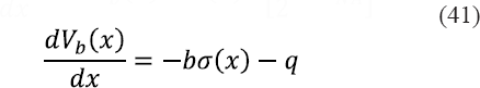
By differentiating equation (12) with respect to x, the formulation leads to equation 13:

Where and

The longitudinal strain at the base of the FGM beam, using equations (3) and (8) is given by equation (15):

Where b, α, ΔT denote the FG beam's width, thermal expansion and temperature load respectively. The strain at the top of the FRP plate is given by equation (16):

Where E
Consideration of horizontal equilibrium gives equation (17):
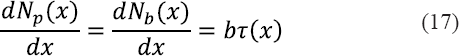
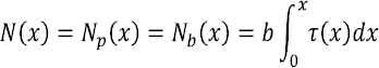
Where(18)
The relationship between the moments in the two adherends by assuming an equal curvature between them can be expressed as:

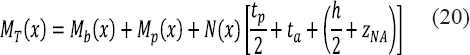
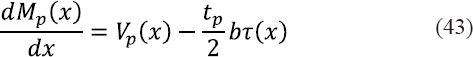
The total applied moment MT(x) at any section of the plated beam in Fig. 3 gives equation (20):
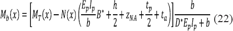
The bending moment in each adherend, expressed as a function of the total applied moment and the interfacial shear stress, is given in equation (21) and (22):

The first derivation of the bending moment in each adherend gives equation (23) and (24):


By substituting Equations (15) and (16) into Equation (13) and differentiating the resulting equation, it takes the following form:
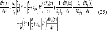
By substituting the shear forces from Equations (23) and (24) and axial forces Equation (25) into the resulting equation yields the following governing differential equation for the interfacial shear stress:

The general solution to equation (26) is given by equation (27):

Where:

And

In the case of uniformly distributed load q, the shear force is given by equation (30):

The constants of integration (B1 and B2) in equation (27) are determined by applying the boundary conditions. The first boundary condition is the applied bending moment at x = 0. Here, the moment at the plate end M (0) and the axial force of either the beam or the soffit plate (Nb(0) = Np(0)) are zero. As a result, the moment in the section at the plate curtailment is resisted by the beam alone and can be expressed as follows in equation (31):

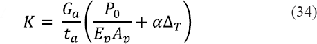
Substituting equations (15) and (16) into equation (13), and applying the above boundary condition, gives:

Where

And
By substituting equation (27) into equation (32), B2 can be determined in equation (35):
Due to the symmetry of the applied load, the inter-facial shear stress at mid-span is zero. Therefore, the second boundary condition can be determined in equation (36):
In the cases where λLp12 > 10, tanh(λLp/2) ~ 1 and the expression of Bl can be simplified to:
The governing differential equation for the interfa-cial normal stress is derived in this section. When the beam is loaded, vertical separation occurs between FGM beam and the bonded plate. This separation creates an interfacial normal stress in the adhesive layer. The normal stress, σ(x), is given as:
Wherewb(x) and wp(x) are vertical displacements of the beam and the plate, respectively.
The equilibrium of the beam and the plate, neglecting second-order terms, leads to the following relationships.
Adherend 1 (Beam):


Adherend 2 (Plate):


Based on the above equilibrium equations, the governing differential equations for the deflections of adherends 1 and 2, expressed in terms of the interfa-cial shear and normal stresses, are given as follows: Adherend 1 (Beam):

Adherend 2 (Plate):

Substitution of equations (45) and (46) into fourth derivative of the interfacial normal stress obtained from equation (38) gives the following governing differential equation for the interfacial normal stress:

The general solution to this fourth-order differential equation is given by equation (48):

For a large value of x it is assumed that the normal stress approaches zero, and as a result C3=C4=0. The general solution therefore becomes:
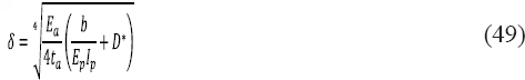
Where


And

The constants C1 and C2 in equation (49) are determined by considering appropriate boundary conditions. The first boundary condition is the zero bending moment at the ends of the bonded plate. Differentiating equation (38) twice and substituting equations (39) and (42) into the resulting expression yields the following relationship at the end:
Since it has been established that M (0) = 0, Nb(0) = N (0) = 0 and Mb(0) = MT(0) at the end of the bonded plate, the above relationship can be expressed as:

Boundary condition 2 concerns the shear force at the end of the bonded plate. Differentiating equation (38) three times and substituting equations (40) and (43) into the resulting expression lead to the following relationship at the plate end:

As the applied shear force at the end of the plate is zero (i.e., Vp(0) = 0), Vb(0) = VT(0). The second boundary can therefore be expressed in equation (56):

Where

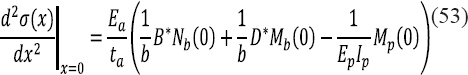
Further differentiation of equation (49) leads to the following expressions for the second and third derivatives of the interfacial normal stress at the plate end:


Since the loading is limited to uniformly distributed loads, the second and higher order derivatives of q become zero. Substituting the boundary conditions into the above two equations then leads to the determination of CI and C2 as follows:


In order to validate the results of the above procedure, a finite element (FE) analysis has been employed using ANSYS software. Given a symmetry of the beam and the mechanical loads, only half of the structure was considered for the ANSYS 3D (Tridimensional) FE model. Furthermore, the Quadratic brick element was used, which includes 8 nodes with three degrees in every node and, in every node there are translations according to the x and z axis. Fig. 4 represents the geometry of structure used before the meshing. A summary of the geometric and material properties is given in Table 1. The span of FG beam is L=3000 mm, the distance from the support to the end of the plate is a = 300 mm. The value of the uniformly distributed load (UDL) is 50 kN/m, the value of the thermal load is 50 oC and the prestressing force applied on the plate is 100 kN which was simulated as a thermal load.

Geometry of the Plated FGM Beam.
Geometric and material properties.

Since the interfacial stresses expressions of the homogenous beams are a special case of the non-homogeneous beam when n=0, then as a verification of the present analytical model, the first results were first compared with those of the model developed by Smith and Teng [9] for the case of a simply supported homogenous beam subjected to a uniformly distributed load only (T = 0 and P0 = 0). The present method is verified, since the results illustrated in Table 2 and Fig. 5 show that there is an excellent agreement between analytical and FE models and the method used by Smith and Teng [9]. The present method is verified, since the results illustrated in Fig. 5 and Table 2 show that there is an excellent agreement between the interfacial stresses of the present method (Analytical and FE models) and the method used by Smith et al [9].

Comparison of interfacial shear and normal stresses for a homogenous beam with a bonded CFRP soffit plate.
Comparison of the Interfacial Stresses of a Homogenous Beam.

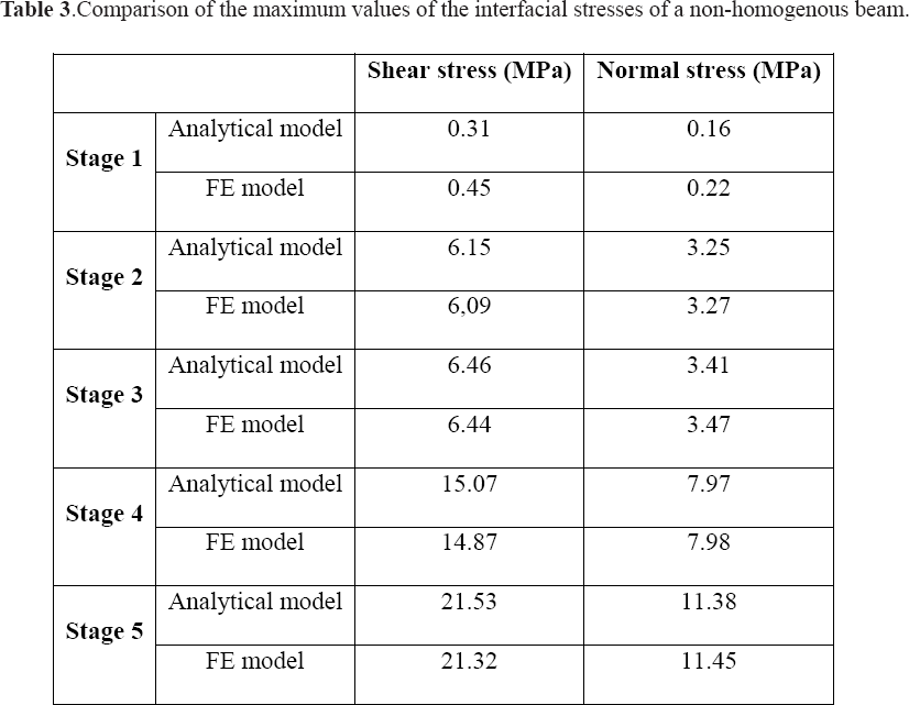
In this original research, the FE numerical results are compared with the analytical results of the non-homogenous FG beam (n > 0) under 5 different stages as described below, the obtained results are shown in Fig.6 −10 and Table 3.

Interfacial Stresses under UDL (Stage 1).
Comparison of the Maximum Values of the Interfacial Stresses of a Non-Homogenous Beam.
Stage 1: Mechanical load (UDL).
Stage 2: Thermal load.
Stage 3: Thermo-Mechanical load.
Stage 4: Prestress load.
Stage 5: Thermo-Mechanical load with prestressing force.
From Fig. 5 - 10 and Table 3, the results confirm that the analytical results agree closely with the FE numerical results. It can be seen form Fig. 6 that 150 there is a significant decrease in the interfacial stresses in comparison with the results shown in Fig. 6, the difference of the maximum value of the shear stress is 2.3 MPa and 1.32 MPa for the normal stress. In other words, the use of the FG beam reduced the interfacial stresses by approximately 85% and 89% for the shear and normal stress respectively, showcasing thus the advantage of functionally graded materials in comparison with the traditional composite materials. Fig. 7 which represent the interfacial stresses of the FG beam under thermal load (Stage 2), shows an increase in comparison with Fig. 6 (Approximately 5.5 MPa and 3 MPa or 1884 % and 1932 % for the shear and normal stress respectively). Fig. 7 shows a small increase of shear and normal stresses 160 in comparison with stage 2 (Approximately 0.3 MPa −5%), this is mainly due to the small maximum values of the interfacial stresses of stage 1 (Fig. 6). Fig. 9 shows a serious increase of the interfacial stresses in comparison with stage 1 with an increase of approximately 14.5 MPa for the shear stress (4761 % or 49 times) and 7.8 MPa for the normal stress (4783 % or 50 times). Fig. 10 represent the interfacial stresses of the FG beam under 3 types of loads (Stage 5), from which it can be seen that the combination of the mechanical, thermal loads and prestressing force cause an increase of approximately 6845 % (69 times) for the shear stress and 7012 % (71 times) for the normal stress. Also, the authors can clearly observe from Fig. 7 −10 that the interfacial stresses 170 vanish at 200 mm from the plate end.
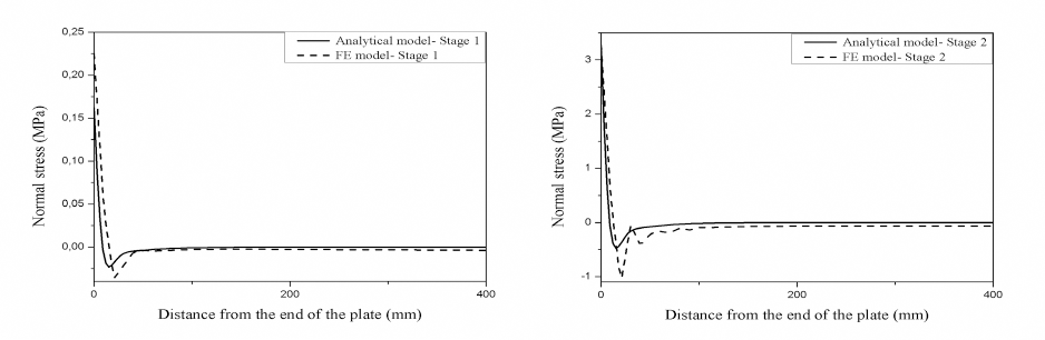
Interfacial Stresses under Thermal Load (Stage 2).
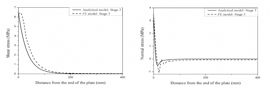
Interfacial Stresses Under Thermo-Mechanical Load (Stage 3).

Interfacial Stresses under Prestressing Force (Stage 4).

Interfacial Stresses under Thermo-Mechanical and a Prestressing Force (Stage 5).
The presented results of this new model, which takes into consideration a combination of different parameters, is close to the practical reality of the structures in their environment. Therefore, this results can serve as a benchmark for future analyses of functionally graded beams strengthened by prestressed carbon fibre reinforced polymer plates.
In this section, we present the numerical results of the present model to study the influence of various parameters on the interfacial stresses of a non-homogenous beam bonded with a prestressed CFRP plate and subjected to a thermo-mechanical load. The studied parameters are the power law index n, the adhesive thickness ta, the adhesive shear modulus Ga, the FRP plate thickness tp and the ratio Ec/ Em.
Influence of the Power Law Index n
Fig. 11 illustrates the effect of the power-law index n on the interfacial shear and normal stresses, it can be seen that the increase of the power-law index n leads to high interfacial stress values, which is essentially due to flexibility of the FG beam since higher values of the power-law index n lead to higher volume fraction of the metallic phase and therefore lower volume fraction of the ceramic phase. It is therefore recommended to use smaller values of the power-law index n in order to minimize the interfacial stresses and optimizing the rehabilitation and resistance impact.

Effect of the Power-Law Index n on the Interfacial Stresses.
From Fig. 12, one can notice that the interfacial shear and normal stresses decrease significantly when the adhesive thickness increases. Therefore, it is preferable to use relatively thick adhesive layers in order to minimize the interfacial stresses.

Effect of the Adhesive Thickness ta on the Interfacial Stresses.
Fig. 13 shows that the shear modulus Ga is proportional with the interfacial stresses, since the increase of the adhesive shear modulus Ga leads to a signifi-cant increase of the shear and normal stresses.

Effect of the adhesive shear modulus Ga on the interfacial stresses.
From Fig. 14, it is seen that the interfacial shear stress is inversely proportional with the FRP plate thickness which is mainly due to the prestressing force. However, the interfacial normal stress seems to decrease until the thickness reaches 3.5 mm then increase afterwards. Therefore, in order to minimize the interfacial shear and normal stresses, the recommended optimum thickness is tp = 3.5 mm.

Effect of the FRP plate thickness tp on the interfacial stresses.
Fig. 15 shows that when the Ec=Em< 1, the interfa-cial stresses decrease as n increases. However, when Ec=Em> 1, the interfacial stresses increase as n increases. Also, Ec=Em ratio is inversely proportional to the shear and normal stresses, since the increase of this ratio leads to a decrease of the interfacial stresses.
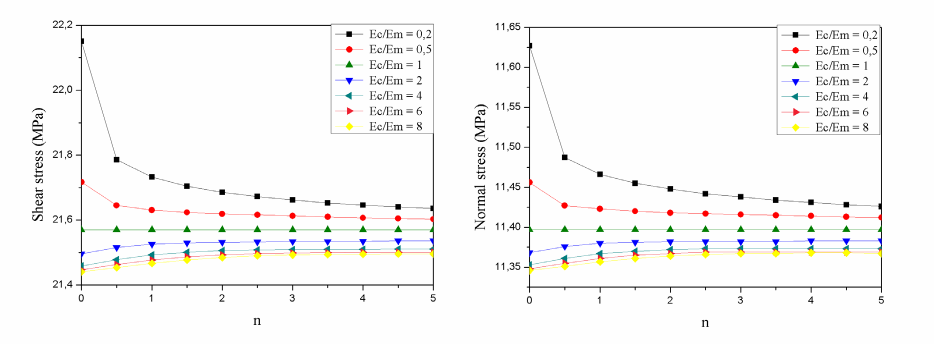
Effect of the Ec/Em ratio on the interfacial stresses.
This research has studied the structure rehabilitation and the debonding phenomenon which is an important failure mode, taking into account a combination of parameters that have been neglected by previous studies. To that purpose, a new model for predicting interfacial shear and normal stresses of a functionally graded beam, reinforced by a prestressed CFRP plate and subjected to a thermo-mechanical load is developed. The used numerical tool allows to simulate the material properties of the functionally graded beam which vary continuously through the thickness of the beam, according to the power distribution law. The analytical results are consistent with the numerical results developed by FE analysis and previous studies, from which, it was found that the interfacial stresses are highly concentrated at the end of the prestressed CFRP plate. Also, the minimization of the interfacial stresses can be achieved by using FG beams with smaller values of the power-law index n as well as higher values of the Ec/Em ratio, thick and flexible adhesive layer and finally, laminate with an optimal thickness of tp = 3.5 mm. The use of the recommended geometrical and material properties of the functionally graded structure (FGM) was found to significantly decrease the inter-facial stresses reducing thus the risk of the debonding phenomenon. Consequently, the results presented in this research are of great interest and can serve as a reference for future studies of functionally graded beams reinforced by prestressed CFRP plates and subjected to different environment stresses.