
Abstract
This article proposes a new task level approach to control the position of macro-mini robotic systems. The proposed method combines redundancy resolution and PI compensation. Taking advantage of the redundancy resolution, this control method accounts for the differences in the dynamics of the macro robot and the mini robot during positioning tasks while ensuring that both robots respect their mechanical limits. The combination with a PI compensation improves the control performance in tracking tasks. This work also presents the adaptation of two other separate methods, namely mid-ranging control and Model Predictive Control, to macro-mini robots. A new macro-mini robot is introduced and experiments, in which the three control methods perform the same trajectories, are conducted. The control performance as well as the advantages or drawbacks of each method are compared. The general behavior of each robot component is also observed and analyzed. Finally, several practical issues and potential future work are discussed.
Introduction
Many applications in robotics require robots to have a large workspace, especially in industry. In many circumstances, the existence of singularities is the main challenge to enlarge the workspace of robots, especially for parallel robots. Redundancy is a potential strategy that has shown many promising results in avoiding singularities and in extending both translational and rotational workspaces of serial robots (see for example Ref. 1 ), and of parallel robots such as Refs.2,3 On the other hand, the workspace’s volume is proportional to the dimension of a robot. Larger robots deal with higher inertia which makes it much more difficult to increase the operational speed. The solution is not as simple as adding more powerful actuators because this problem requires working closely on both sides: the mechanical design and the control system. Once this collaboration is successfully implemented, the speed is significantly enhanced, particularly in studies involving parallel robots such as Refs.4–7 Nonetheless, there is no perfect robot that can have both dominant features: high operational speed and a large workspace. The idea of a macro-mini manipulator was proposed in this context. A macro-mini manipulator is technically a special case of redundancy, which consists of two robots assembled in a serial configuration. It combines two robots that have very different and complementary properties. Then, the output of the macro-mini system can earn the advantages of each robot, as well as reduce their weaknesses. As suggested by the name, the macro is bigger and attached to the base. On the contrary, the mini is much smaller. Thus, fast and dexterous robots are usually selected.
The concept of macro-mini robot architecture was initially introduced in Ref., 8 which was aiming to enhance the accuracy of position control. Several recent studies considering macro-mini systems working in the range of micrometers also exploit this advantage, such as Refs.9,10 In Ref., 11 the authors proved that using this architecture can significantly increase the bandwidth of position control and force control. It also enhances the interaction capability. Later, in Refs.,12,13 impedance control for a macro-mini system was presented. Robotic polishing or milling are popular applications that require accurate force control. Therefore, the macro-mini architecture can be applied, for example in Ref. 14 During the decade following its inception, the idea of macro-mini was bonded with the combination of two serial rigid robots. However, this architecture quickly became diverse afterward with different compositions, as long as the principle mentioned above is applicable. For example, in Ref., 15 the combination of a macro flexible robot and a mini rigid robot was presented, in Refs.,16,17 that of two parallel robots was proposed (one of them can be a cable-driven robot). The parallel configuration of the macro-mini system was also proposed, where the two robots can be mounted on a common base and work on the same task, like one of the two configurations introduced in Ref. 18 This configuration enables to considerably extend the force bandwidth of the combined system as demonstrated in Ref. 19 In Refs.,20,21 the authors proposed the use of a macro robot with a passive mini parallel mechanism for physical human-robot interaction (pHRI). This architecture has clearly demonstrated promising results in this domain.
From a mechanical standpoint, the accurate control of the position of a robot with a high bandwidth requires agility. However, for tasks that require a large workspace, the robot needs to be large and therefore heavy, which makes it difficult to produce motion with a high bandwidth. This is the main reason for taking a macro-mini approach in this work. Only the lightweight mini robot needs to be able to operate at a high bandwidth, which is much more feasible. This approach has a significant impact on the controller, namely the proposed PI + RR paradigm can be used which in essence implements a synergy between mechanical design and control, based on the dynamic modeling of the system.
The dynamic model plays an important role in most control methods, from classical to modern, as discussed in Ref. 22 Model-based approaches certainly yield great results but the analytical dynamic model may not be available. Recently, data-driven modeling like identification techniques is preferred and the dynamic model can be computed numerically. For that reason, in this study, the macro-mini robot is revisited and the motion control problem is considered systematically to overcome existing drawbacks. Firstly, the position control of each robot is assumed to be given or solved separately. The subsystem that includes the macro or the mini and their position controller is then modeled as a linear system. In order to take dynamic effects into account, the model of each subsystem is identified while considering its interaction with the other. After this stage, the combined system is seen as a mathematical model. The control techniques that work on top of this model are investigated. In addition to simulations, the control scheme of a new macro-mini system is introduced. Experiments are carried out on this system to verify control performance as well as to highlight practical implementation issues for each method.
The rest of this paper is structured as follows. Section 2 first describes the kinematics of the macro-mini system. A mathematical model is then derived based on several assumptions and the research problem is stated. The proposed control method is presented in Section 3. Other control methods are also adapted and applied to the macro-mini robotic scheme. They are presented in Section 4. A new prototype is introduced and the experiments are explained in Section 5. Experiments are carried on the new prototype and the performance of each of the control methods is compared. The advantages and drawbacks of each method are pointed out. Finally, some conclusions and future work are discussed in Section 6
Problem formulation
The macro-mini system consists of two manipulators connected in series. A large robot, referred to as the macro robot, is fixed to the base. Then, a small robot, referred to as the mini robot, is attached to the end-effector of the macro. The macro and the mini can have different numbers of degrees of freedom (DoF). However, the end-effector can perform
Kinematic model of the macro-mini system
An arbitrary Cartesian work-frame

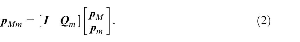
Rewriting this equation in matrix form yields
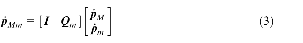
Taking the derivative of both sides with respect to time, the velocity equation is written as
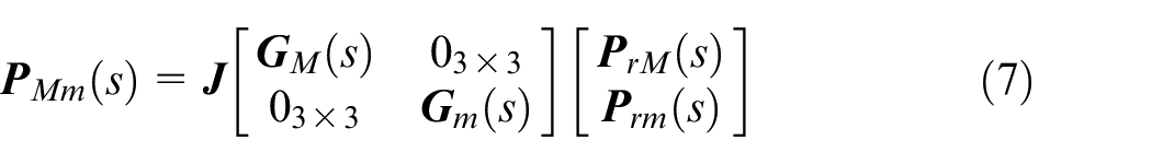
in which the Jacobian matrix of the macro-mini system is now defined as

Matrix
Mathematical model and assumptions
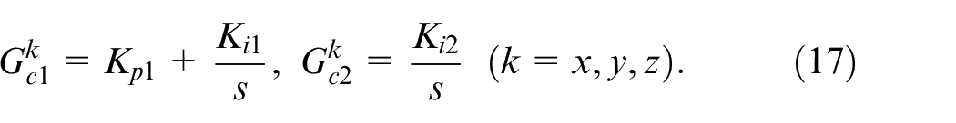
First of all, the position of each robot is assumed to be managed by its own controller. More specifically, each robot is a standalone system including a trajectory tracking controller that functions independently. On each axis, the dynamics of each robot including the position controller are assumed to be expressed by a linear transfer function defined as
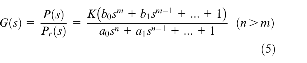
in which K is a proportional gain,
In this article,
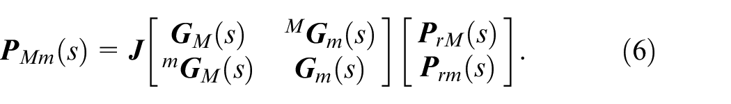
However, the mechanical design of the robots can produce independent motion on each axis and the inner control loops are assumed to function precisely. Then, the motion of one axis is not affected by that of the others. Thus,
in which
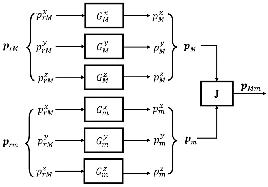
Diagram of the simplified macro-mini model.
Hence, a simplified mathematical model of the macro-mini system can be derived from the separate model of each robot, which can be easier to determine or simpler to identify. This study applies the cascade model where the proposed control method works at the task-level, on top of the position controller of the macro and the mini. Mid-ranging control and model predictive control are also adapted to apply to this control scheme.
Proposed control method: Combination of PI compensation and redundancy resolution (PI+RR)
In general, the relationship between the velocity in the joint coordinates and that in the task coordinates is expressed as

in which

in which
Weighted generalized inverse and the dynamical consistency
As mentioned above, the dynamics of the macro and the mini robots are drastically different. In order to take this factor into account while determining the generalized inverse
where

where
Weighting matrix
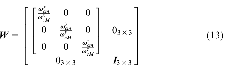
where
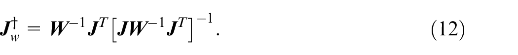
In Ref., 25 the authors showed that the generalized inverse matrix that is consistent with the dynamics of the robot for non-redundant and redundant manipulators is
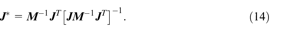
in which
Penalty function and physical limits
Beside the differences in the dynamics, the physical limits of the macro and the mini are also very different. The mini has a very small workspace compared to that of the macro. As a result, the proposed controller needs to slow down the mini whenever it approaches to these ends. A penalty function
(i)
(ii)
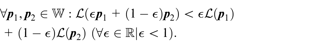
(iii) The minimum of

The problem of handling the physical limits turns into obtaining the nullspace solution, which is reflected on vector

where a constant diagonal matrix
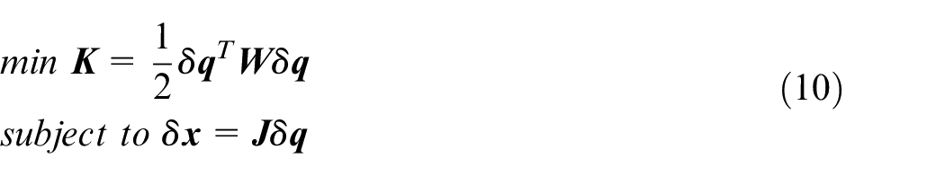
Implementation
In order to implement equation (11), it is rewritten in a discrete form using the backward difference approximation,
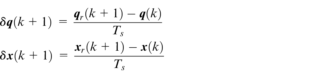
An iterative procedure can be obtained for this system as

in which the feedback positions
Lastly, a PI compensation can be added and acts as a low-pass filter to keep the input signal from being too aggressive. The output signal from this controller is fed into the redundancy resolution. Moreover, the PI component also eliminates the steady-state error, which happens when the dynamics of the system are not modeled perfectly. The schematic of the proposed control method is finally illustrated in Figure 2.
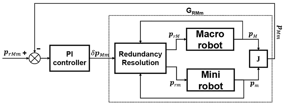
Diagram of the proposed control method (PI + RR).
Adaptation of other control methods to multiple-DoF macro-mini systems
Other control methods can be adapted into the cascade layout in this work. Therefrom, the performance of the proposed control can be compared. In this work, mid-ranging control and model predictive control are selected as respectively presented in the following sections.
Mid-ranging control
Valve position controller (VPC) was investigated in Ref. 26 in order to regulate Multiple-Input Single-Output (MISO) systems using SISO control methods. Mid-ranging control is a modified version of VPC and it is analyzed in more detail in Ref. 27 A simulation analysis of this control method for a macro-mini manipulator was studied in Ref. 28 It was also adapted to a 1-DoF macro/micro actuation in Ref. 18 In this work, this method is generalized for multiple redundant DoF systems and the new scheme is shown in Figure 3.
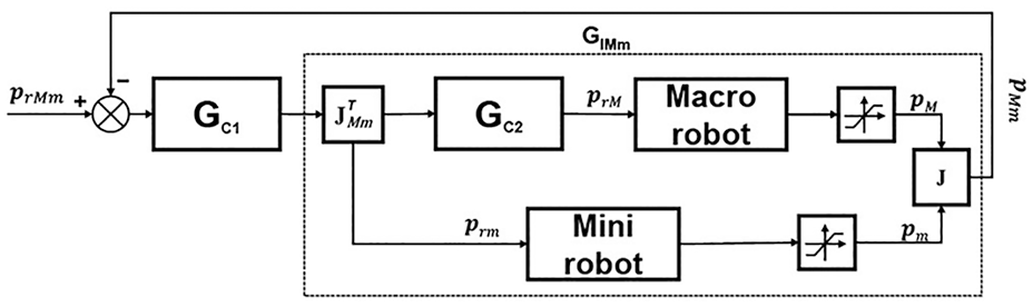
Diagram of mid-ranging controller.
Similarly to the conventional scheme,
After doing this modification, the macro-mini system is very much alike a combination of independent SISO systems, for which the plant is represented by
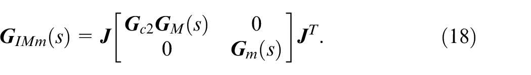
A classical problem is established on each axis where the parameters of
Model predictive control
From the transfer function in equation (7), a discrete state space model can be derived at a particular sampling time
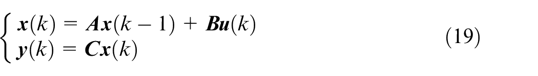
in which
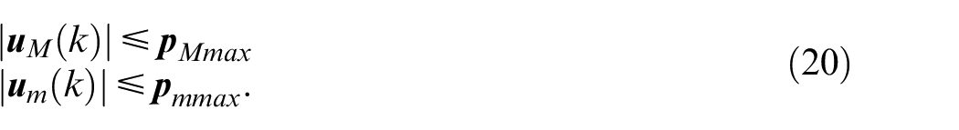
The limited workspace of the two robots is represented by inequality constraints. Assuming a symmetrical workspace, one can write
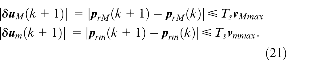
Along with these restrictions, the macro and the mini are also limited by maximum velocities, which can be written as
Based on equation (19), at a specific time step
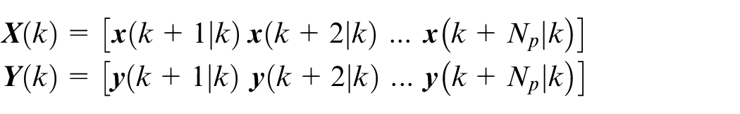
where

where
The MPC determines a unique optimal control sequence
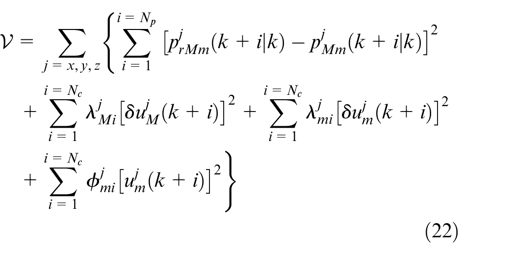
in which
Generally speaking, MPC takes into consideration all factors that affect the performance. In the meantime, the need to adjust several parameters simultaneously in order to achieve this control objective is a challenge. As also mentioned in Ref.,
30
tuning these parameters still requires trial-and-error with some acquired experience. There is no systematic or analytical method for this tuning process. However, the output changes can be partially predicted. In this case,
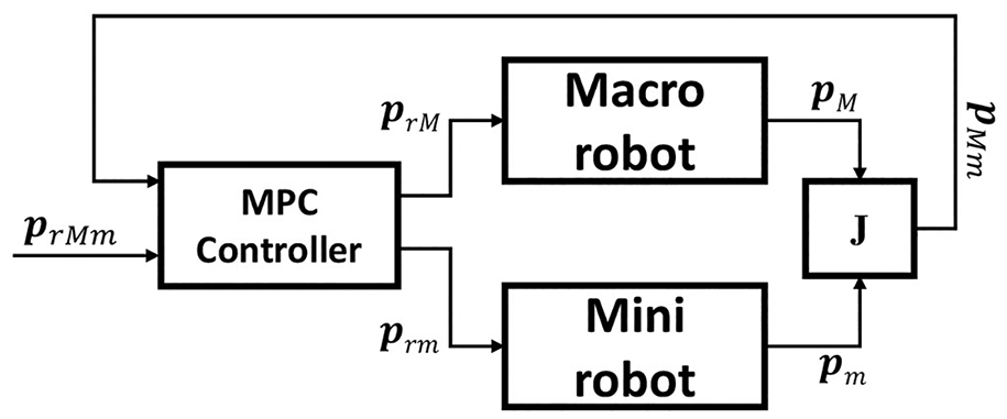
Diagram of MPC control.
Experimental results
Different experiments are carried out in this section on a new design of macro-mini robot, in which a 3-DoF gantry robot is coupled to a kinematically redundant (6+3)-DoF parallel robot proposed in Ref. 31 The schematic of the new robotic system is illustrated in Figure 5(a).
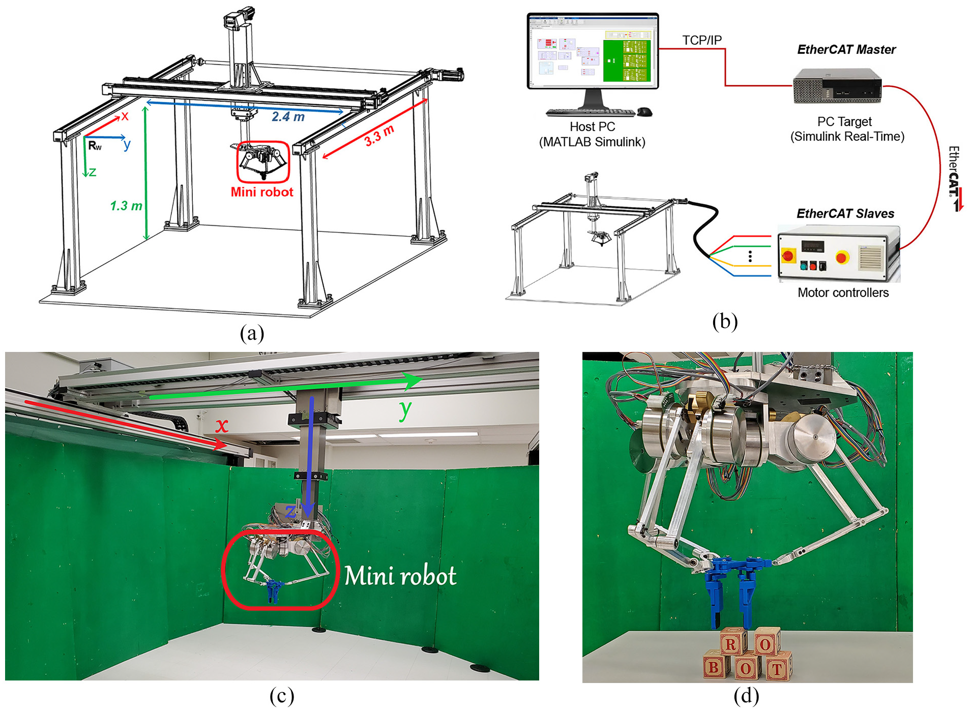
Experimental setup: (a) schematic of the macro-mini system, (b) hardware block diagram, (c) macro-mini system, and (d) the mini robot.
On the macro side, the actuator on each axis is a Parker brushless servo motor MPJ1153C with a gearbox 7:1 in the
The mini robot consists of a moving platform and three fully actuated legs. This architecture supports 3 DoFs in translation, 3 DoFs in rotation and 3 other redundant DoFs. Regarding the number of redundant DoFs with the macro robot, only three translational DoFs are considered for the redundant control of the macro-mini system. The other DoFs are unique to the mini and used as an extension. The total mass and the moving mass of this robot are respectively
The linear model of each sub-system, namely the macro robot and the mini robot, is identified and presented in Appendix B. Considering the combination of the two robots in
In most cases, the workspaces of the macro and the mini are symmetrical, that is,
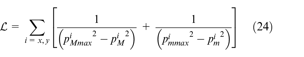
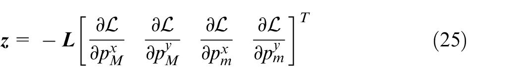
The value of the penalty function and the negative gradient vector in the one dimensional case are given below and illustrated in Figure 6.
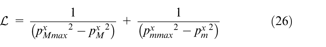
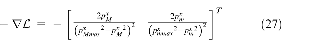
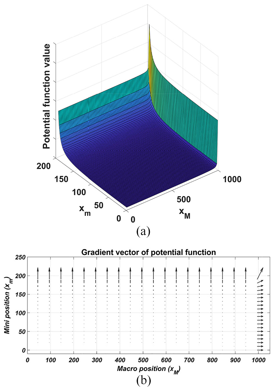
An illustration of the penalty function on the
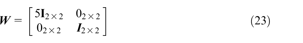
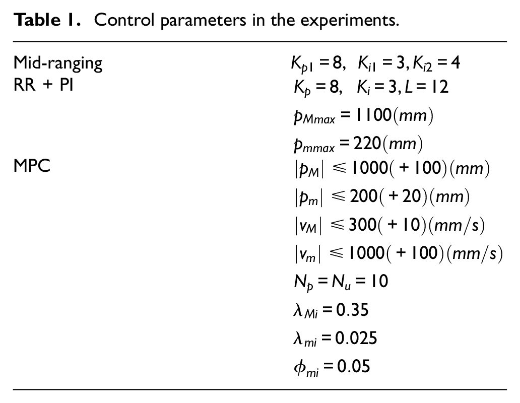
The setup for the experiment in this work follows the preferred arrangement in which
Control parameters in the experiments.
In the first set of experiments, the robot performs the same trajectory along the
Simulation and experiment on the controller behavior in the frequency domain
The first trajectory is the sum of two sine waves with different frequencies given as

in which
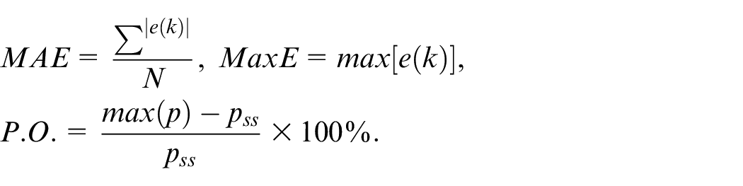
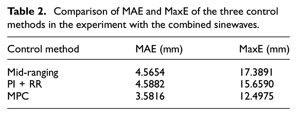
Firstly, the tracking performance of the macro-mini system using the three control methods is experimented and the results are shown in Figure 7. The tracking error of each approach is examined and compared as summarized in Table 2 regarding MAE and MaxE. The proposed method PI + RR demonstrates a performance similar to that of the mid-ranging control in this comparison. Also, MPC shows improvements on both indices compared to the others.
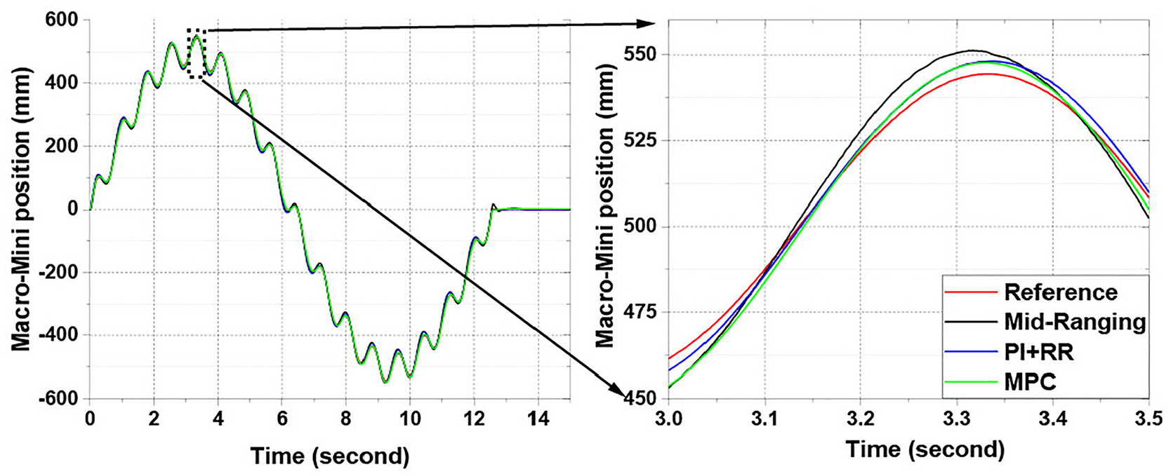
The macro-mini position response in three experiments with the control methods.
Comparison of MAE and MaxE of the three control methods in the experiment with the combined sinewaves.
Furthermore, the same desired signal is used in simulations. The linear model of equation (7) and each of the three control methods are respectively applied. The motion of each robot component, namely the macro and the mini, during the trajectory from the simulations is compared to that from the experiments as can be seen in Figure 8 for mid-ranging control, in Figure 9 for PI + RR and in Figure 10 for MPC. It can be noted that the simulations and the experiments return similar results. On one hand, the results validate the linear model in Appendix B. On the other hand, the three control methods in the task space demonstrate consistent responses in the frequency domain, in which the macro is responsible for low frequency motion and the mini handles high frequency motion. The same behavior is achieved in different ways, either with a simple linear controller or a complex optimal controller. These results show that dividing tasks based on frequency response is an appropriate strategy for the macro-mini system. The control methods are then tested on a the second trajectory for their different behavior in handling constraints. Finally, since the results of the simulations and experiments are very similar, the parameters can be tuned based on simulation, even though this may not lead to the optimal set of parameters in practice.
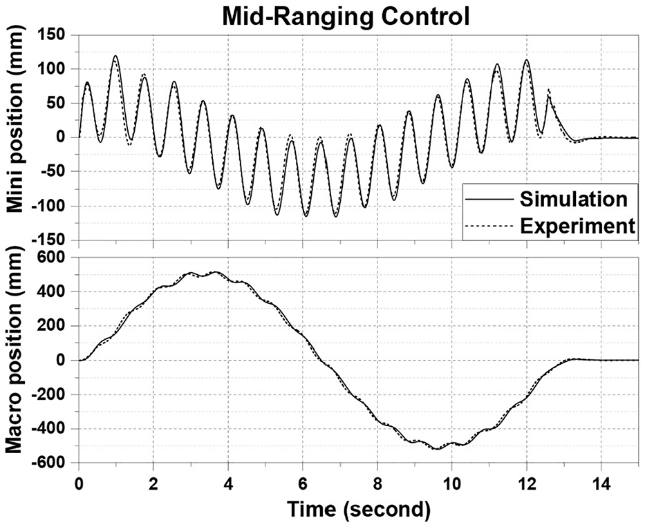
Macro position and Mini position in a simulation and an experiment with Mid-Ranging Control.
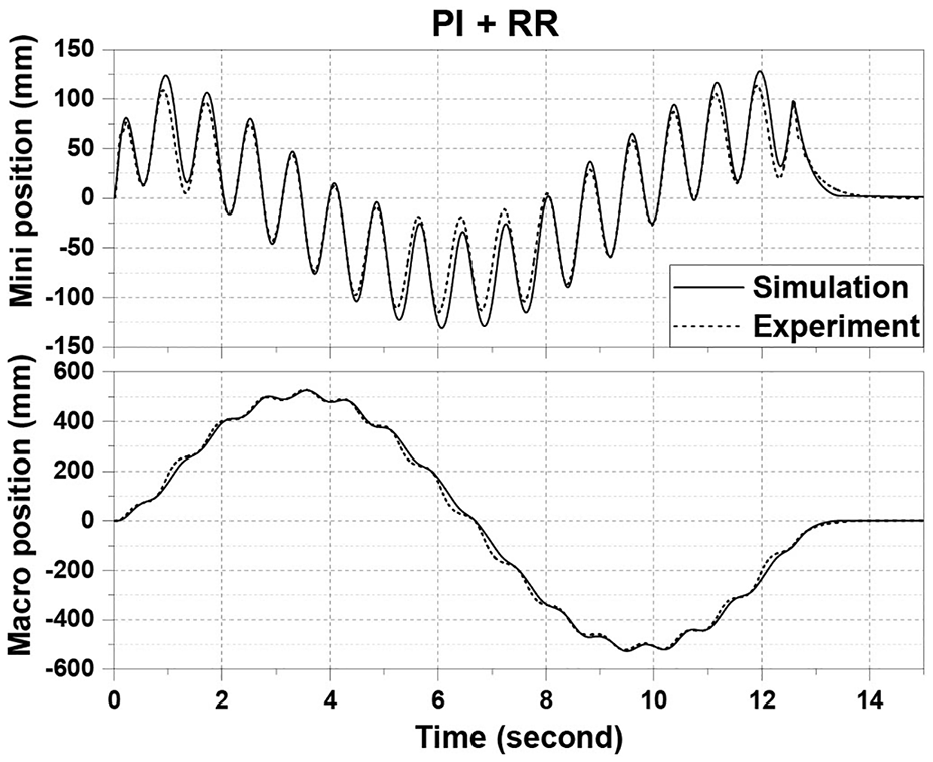
Macro position and Mini position in a simulation and an experiment with PI + RR.
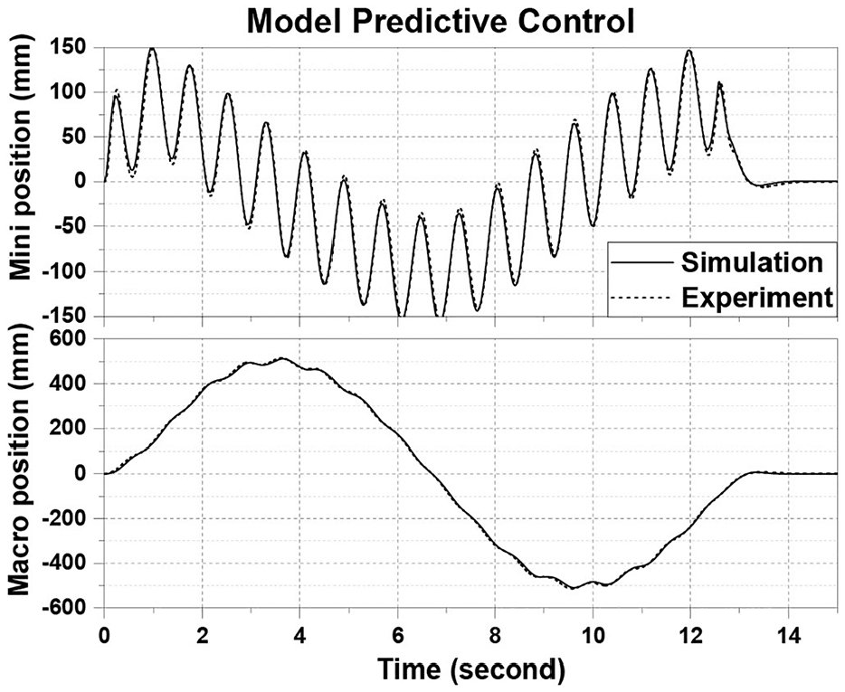
Macro position and Mini position in a simulation and an experiment with MPC.
Experiments on constraint handling and mid-ranging of the mini
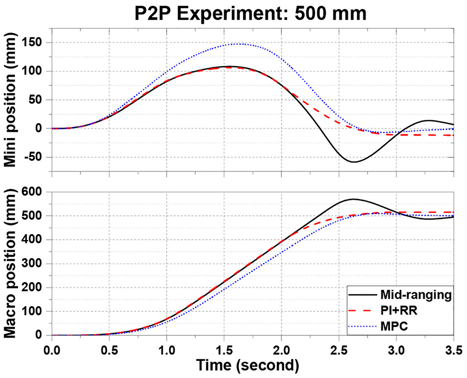
The second trajectory consists of two point-to-point motions. The robot is commanded to go from

in which
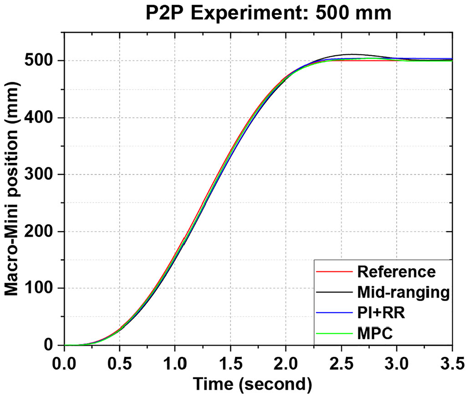
The macro-mini position response in an experiment point-to-point 500 mm.
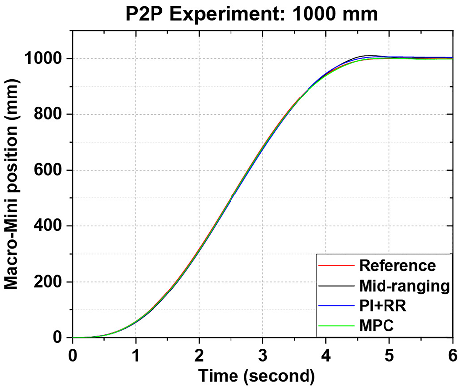
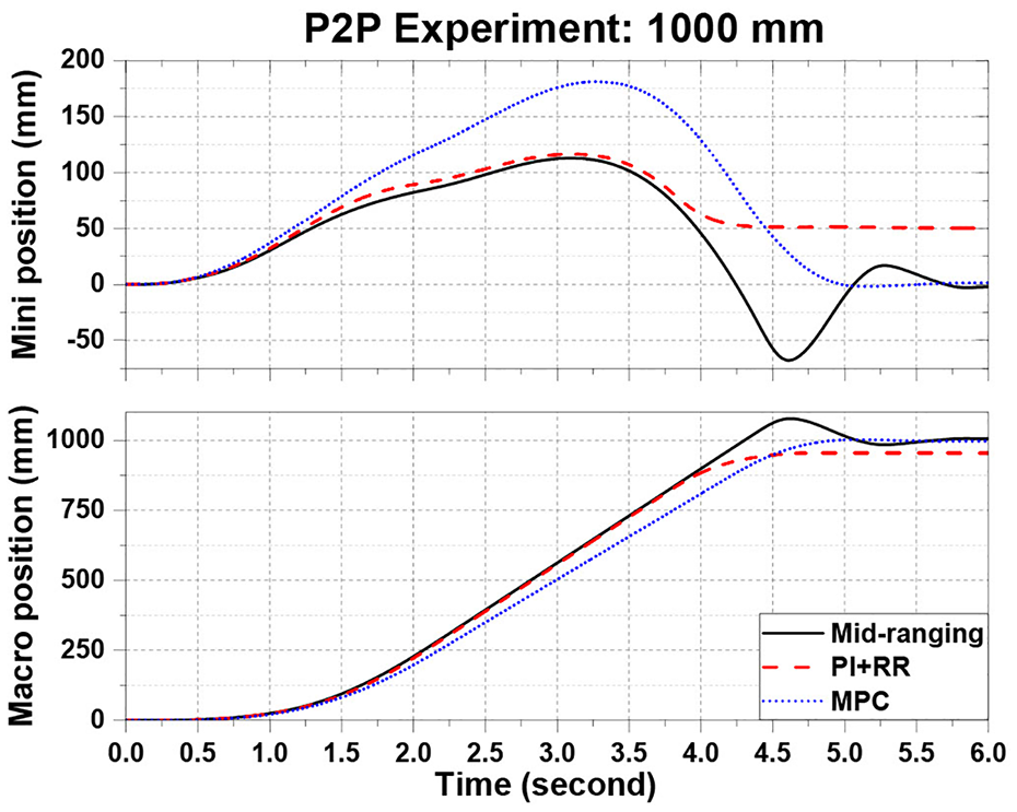
The macro-mini position response in an experiment point-to-point 1000 mm.
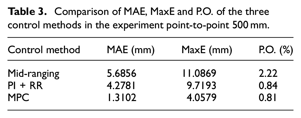
Comparison of MAE, MaxE and P.O. of the three control methods in the experiment point-to-point 500 mm.
Comparison of MAE, MaxE and P.O. of the three control methods in the experiment point-to-point 1000 mm.
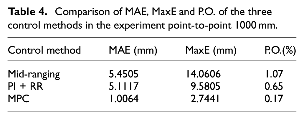
The motion of the macro and the mini obtained with the three different controllers is recorded and shown in Figures 13 and 14. In this case, the macro and the mini demonstrate different reactions when the limits are approached. In the first point-to-point experiment, the three control methods show a similar behavior. In fact, the three methods can relatively mid-range the mini. For PI + RR, the results depend on the definition of the penalty function, while for MPC, the results depend on how the mid-range condition is compared to the other control objectives. More interestingly, the differences in handling limits are shown in the second point-to-point experiment, where the macro limit is also reached. Mid-ranging control certainly cannot take any constraint into consideration. PI + RR tries to balance the limits of the macro and the mini so that no limit is reached. Therefore, the mini does not return to its origin. Lastly, MPC performs normally as long as no constraint is violated.
Point to Point experiment from
Point to Point experiment from
Demonstration of the multiple-DoF combination
Control performance has been analyzed in the previous section. One of the control methods, namely MPC, is selected and the implementation of the proposed method is extended to multiple dimensions (position in
More detail can be seen from the recorded video that accompanies this article (https://youtu.be/pZClOVh\_lPo). Wooden blocks are picked and placed so that they finally form the word “ROBOT.” This task includes nearly all possible motions: short-range translation, long-range translation, rotation about the
Discussion
The mid-ranging control is quite straightforward to apply. On the positive side, the bandwidth of the combined system is clearly extended as PI parameters are increased. Also, when PI parameters are high enough, control error is reduced and becomes much better compared to that of either the macro or the mini. However, the closed-loop system is controlled based on feedback signals, which are the current position of the macro and the mini. Thus, measurement noise and external disturbances are reflected on the control signal or even amplified. This factor causes vibrations and limits the value of the proportional gain Kp. Even though mid-ranging control is relatively simple and yet effective in many cases, it should not be recommended in some specific situations where tight constraints must be satisfied. As long as the mathematical model is precise, MPC is a powerful tool that gives the flexibility to improve control performance and handle constraints. Nevertheless, many parameters need to be adjusted, which may be a challenge. It also requires extensive computing capability as the number of DoF is increased.
PI + RR is proposed as a compromise in this context. The method mainly consists of matrix multiplications. Therefore, it is simple to implement and it does not require much computing power compared to MPC. Constraints, like physical limits, can be basically handled, while no prior information of the desired trajectory is required. Adversely, it can make the system become nonlinear near the physical limits and the nonlinearity depends much on the choice of the penalty function. Thence, each method presented above has its own advantages and drawbacks.
Conclusion
In this article, a new architecture of macro-mini system is introduced. After that, a mathematical model of the system is formalized. Some analysis is verified in practice in order to simplify this model. A new method combining PI and the redundancy resolution is proposed. Mid-ranging control and MPC are adapted and generalized for multi-DoF redundant macro-mini systems. The control architecture proposed in this work enables to simply generate trajectories in the task space, which is clearer and more visual. In addition to the theoretical analysis, each control method can take advantage of available MATLAB toolboxes in examining and tuning parameters. Then, simulations and experiments have been carried out. Firstly, the identified model and the task-space approach were validated. Secondly, the performance of the three control methods can be compared. In the frequency domain, the three controllers yield similar behaviors, in which the macro handles low frequencies of the desired input and the mini is responsible for the high frequencies. The experimental results also demonstrate the better ability of the proposed method to reduce the control error and the overshoot compared to the mid-ranging control but not as significantly as MPC. Additionally, the workspace limits can be simply included based on the definition of a penalty function, while this type of constraints cannot be considered in the mid-ranging controller. On the other hand, the proposed method requires much less computing power than MPC and does not need prior information, for example
In practice, the proposed approaches are relatively sensitive to measurement noise, which affects more seriously mid-ranging control and PI + RR. A Kalman filter was applied to reduce this effect. Additional sensors can be used in the future so that the effect of noise can be weakened in the feedback signals. Besides, the combined system is assumed to be decoupled. This hypothesis is to simplify the dynamic model at low frequencies but it is not completely true. Small coupling still exists and can be observed in the identification process. The mini position is not absolutely zero at high frequencies in the green rectangle. Furthermore, the nonlinearity of the proposed method PI + RR, as well as of the mid-ranging control and MPC, near the limits will also need further examinations in more detail in future works. The weighting matrix is constant in this work but it can be variable and frequency-dependent to better represent the dynamical relationship between the macro and the mini.
Finally, a further investigation into the coupling terms
Footnotes
Appendix A
Appendix B
Declaration of conflicting interests
The author(s) declared no potential conflicts of interest with respect to the research, authorship, and/or publication of this article.
Funding
The author(s) disclosed receipt of the following financial support for the research, authorship, and/or publication of this article: The authors would like to acknowledge the financial support of the Natural Sciences and Engineering Research Council of Canada (NSERC). The authors would also like to thank Simon Foucault for his support with the experimental setup and the video demo.