
Abstract
The 9-degrees-of-freedom (DOF) machine is used to lay the rotating mold driven by the positioner. In order to reduce the 9-DOF machine to a 6-DOF non-redundant structure, this paper proposes a redundancy resolution method based on synthesized global and local performance indices. Since the number of non-redundant machine types is enormous, all non-redundant machines are divided into six classes depending on the redundant joints, called axis assignment schemes. After defining the global and the local performance indices of the non-redundant machine, the redundancy resolution method is proposed. It consists of three parts: Firstly, refine the machine types of each axis assignment scheme based on the average global indices. Then, select the best axis assignment scheme by comparing the scheme’s local indices for a given mold. Finally, optimize the non-redundant machine type contained in the optimal scheme with the objective of superior local indices and continuous positioner rotation space. In the experiment, using the air-inlet as an example, two motion planning methods gave different motion trajectories for the 7-DOF layup system. The effectiveness of the proposed method was verified analytically by comparing the joint motion and fiber placement speed of the optimal machine type with other types.
Keywords
Introduction
Motivation
Due to composites’ good strength-to-weight ratio, durability, shaping flexibility, and corrosion resistance are widely used in many fields such as aerospace, automotive, and marine industries. Automated processes have always been a research hotspot in composite manufacturing. Among them, automated fiber placement (AFP) is one of the primary methods for manufacturing composite structures.1–3 Today, as composite parts become more complex in shape, fiber placement systems have increased their motion flexibility by, for example, increasing the number of joints in the AFP machine and collaborating with a positioner that rotates the mold.
The AFP machine studied in this paper is 9 degrees of freedom (DOFs), consisting of four translational joints and five rotational joints. The machine is used for laying a mold mounted on a positioner flange. The mold can rotate with the positioner around its central axis (Figure 1). For a fiber placement task requiring only 6 DOF, the manufacturing system’s redundancy increases the motion’s flexibility and makes motion planning difficult. Therefore, the redundancy optimization problem is an essential issue for engineering applications.
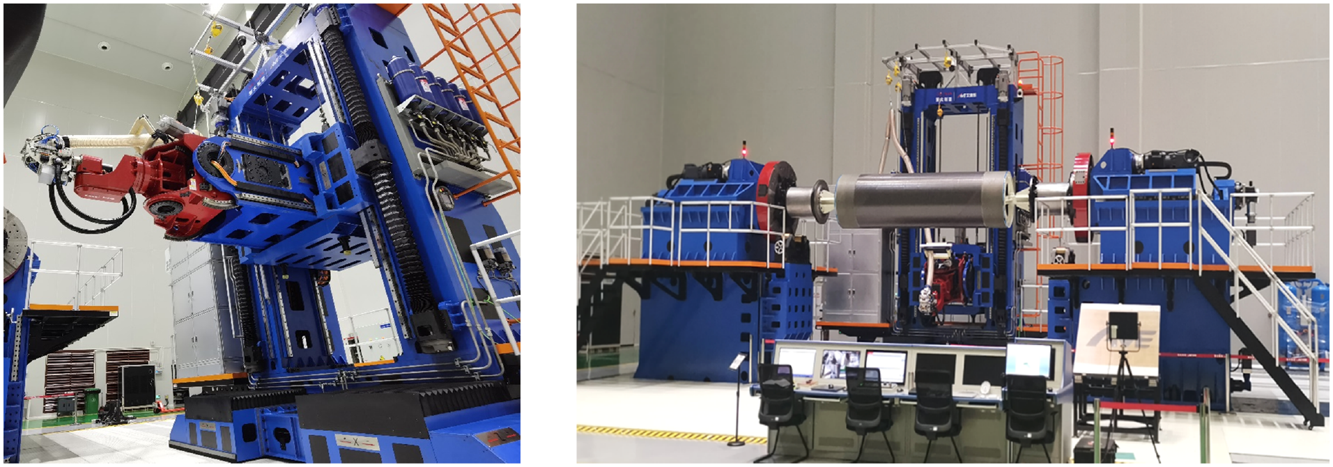
The 9 DOFs machine and the positioner.
Related works
Since the inverse kinematic relationship from Cartesian space to joint space is a one-to-many relationship, controlling the redundancy manipulator is challenging. At the same time, since the redundancy manipulator has a more expansive operation space and additional DOFs to satisfy multiple functions, many scholars have established various posture-dependent performance indices and improved the related performance using redundancy. For example, Yoshikawa 4 proposed the manipulability index to measure the kinematic capability of the manipulator’s end-effector in all directions. Based on the manipulability index, Agarwal 5 used a fuzzy clustering method to obtain the path of a 4-DOF redundancy manipulator with optimal manipulability. García et al. 6 normalized the manipulability and condition number and proposed a three-stage optimization process to achieve single- or multi-objective redundant resolution. For singularity avoidance, FarzanehKaloorazi et al. 7 used the Jacobi matrix determinant value as a local index to quantify the distance from the manipulator to the singularities. They used a particle swarm optimization (PSO) algorithm to solve the redundancy problem of the system. Dubey and Luh 8 constructed manipulator-velocity ratio (MVR) and manipulator-mechanical advantage (MMA) indices in terms of both force and velocity, respectively, to optimize redundant manipulator motion using gradient projection. Kim and Yoon 9 proposed the motion acceleration radius (MAR) index and established a closed inverse kinematic equation to optimize the dynamic uniformity of the redundant robot. The robot transmission ratio (RTR) index was proposed by Zargarbashi et al., 10 which obtained the RTR map of a redundant robot to produce a prescribed robot pose in machining operations. Xiong et al. 11 also proposed a new stiffness-based performance index to optimize the robot’s end-effector posture when moving along the tool path.
In addition to using local indices related to the manipulator’s configuration, several alternative methods have been developed to generate manipulator motions for processing complex-shaped workpieces, taking into account the constraints imposed by the actuators and avoiding collisions between work cell components. These methods are based on the direct optimization of global objective functions describing the total travel time, the trajectory smoothness, etc. For example, with the objective of the shortest working time, the original continuous-time optimal problem is transformed into a discrete problem by discretizing the robot joint space and representing the desired trajectory as the shortest path on the graph.12–14 Fang et al. 15 proposed an optimal trajectory planning method in robotic welding. A beam search algorithm was used to determine the solution with minimum joint motion. Lu et al. 16 used a combination of the Differential Evolution (DE) algorithm and Dijkstra’s shortest path algorithm to determine the collision-free trajectory with minimum joint motion. Kang et al. 17 established a method to obtain a smooth collision-free path for a manipulator by combining the quantum annealing method and a two-stage gradient descent method. Hemmerle and Prinz 18 solved the workpiece placement and redundancy problem for a collaborative welding robot by minimizing the motion of each joint along the path and the joint median deviation. Debout et al. 19 smoothed the end-effector path by a filtering method. To solve the system redundancy problem, they globally minimized the curvature variation of the rotational axis orders and the tool path length. Doan and Lin 20 integrated the kinematic limit distance, singularity, and obstacle avoidance of robot joints into one objective function. They used the PSO algorithm to achieve redundant robot placement optimization and redundancy resolution. Gao et al. 21 used a modified Rapid Exploration Random Tree (RRT*) algorithm to solve the continuous collision-free welding motion planning problem by considering the welding angular redundancy. Huo and Baron 22 developed a self-adaptation of weights for joint-limits and singularity avoidances method for solving the six-axis robot redundancy problem.
In addition to the objectives related to the joints’ motion and machining efficiency, the redundancy of manipulators can also accomplish other requirements for specific occasions. For example, with minimum energy consumption as a goal, Ayten et al. 23 eliminated redundant linkages by creating virtual linkages to simplify operations and plan redundant manipulator motions. Korayem and Nikoobin 24 used an indirect solution to the open-loop optimal control problem to solve the trajectory planning problem to improve the redundant system’s load-carrying capacity.
For solving the redundancy problem of a hyper-redundant layup system composed of two mechanisms, two strategies exist: One strategy is to treat the two mechanisms as a whole, as the above method, but the main problem is the high cost (computational cost, time cost, and control cost) and the possible limitation of the number of axes that the CNC can link. That is because the inverse kinematic solutions for the given task will increase exponentially with the number of redundant joints. Therefore, some optimization methods based on solution space discretization, or taking the solution boundary as a constraint, due to their substantially enlarged search space, have to take longer and more computations to obtain better results. On the other hand, the increase in the number of task points will also raise the computational cost. Also, in practical applications, the greater the number of joints involved in continuous motion during the machining phase, the more difficult it is to control the machining accuracy, kinematics, and dynamics. Therefore, for optimization objectives such as joint smoothing, time-optimal, and minimum energy consumption that examine overall performance, the more task points there are, the more complex and costly the optimization will be.
Hence, for a fiber placement system with a 9 DOFs machine and positioner, we propose an alternative strategy based on the reduction of DOFs.
Our strategy and organization of this paper
Our strategy is based on collaboration matching. That is the mold motion with the positioner, solving the redundancy problem of the 9 DOFs machine based on the best match between the machine performance and the rotating mold. The redundancy of the machine is solved by locking its joints to reduce it to a non-redundant structure of 6 DOFs. Locking certain joints while satisfying the layup requirements is more utilized for engineering implementation, and reducing system DOFs lightens the burden for motion planning and system control.
Thus, based on the system consisting of a rotary positioner with the 9 DOFs redundant machine, the choice was made to leave only one redundant joint, the positioner rotation. Hence, the non-redundant machine with the positioner makes the overall system 7 DOFs. Compared to 10 DOFs, the system flexibility is reduced, but the mold can change its position through the positioner, providing sufficient flexibility for the layup. However, the locked joints cannot be arbitrarily specified either. We expect the mold to have a sizeable admissible rotation space, and the machine is reachable and performs well within this space. In order to obtain such a superior 7 DOFs system, this paper proposes a redundancy resolution method for the 9 DOFs layup machine based on synthesized global and local performance indices by locking the machine’s rotational joints.
Each joint-locked combination and angle will define a machine type. Different machine types have different workspaces and performance distribution. Therefore, in this paper, we first classify all machine types according to their locked joints to obtain six axis assignment schemes. Then, the global and local indices are proposed to describe the non-redundant machine’s performance. The proposed redundancy resolution method consists of three steps: First, the machine types within the schemes are refined using the global indices maps. Then, different schemes’ local indices distribution curves are calculated, and the optimal axis assignment scheme is selected by comparing the scheme’s local indices for a given mold. Finally, in the optimal scheme, the local indices and the continuity of positioner rotational space are optimized to obtain the optimal machine type for a given path.
The rest of the paper is organized as follows. Section 2 gives the 9-DOF machine kinematic model and six kinds of axis assignment schemes. Section 3 defines three global and four local indices. Section 4 gives the steps of redundancy resolution for a 9-DOF machine. Section 5 gives the optimization result using an air inlet mold as an example and illustrates the proposed method’s effectiveness by comparing the joint and layup speed profiles of different machine types, followed by the conclusions in Section 6.
Kinematic modeling and axis assignment schemes for 9-DOF horizontal machine
As shown in Figure 2, The 9 DOFs horizontal machine includes four translational joints and five rotational joints.
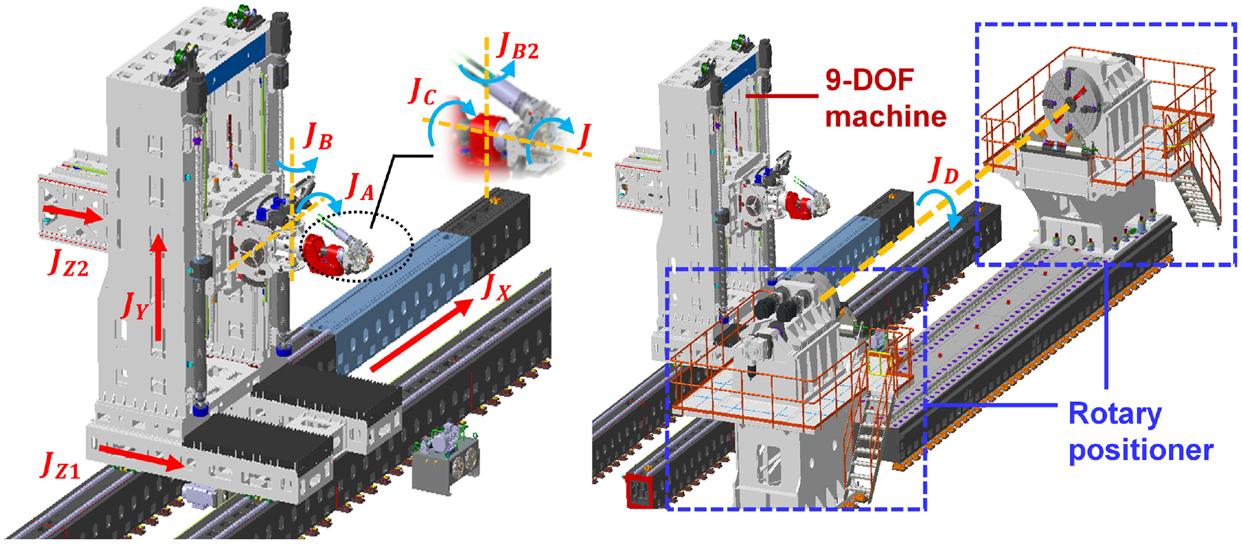
The 9 DOFs horizontal machine and the fiber placement system with positioner.
The fiber placement head employs up to
Kinematics modeling
Based on the Denavit-Hartenberg Modified (DHM) model, 25 the kinematic model of the 9 DOFs machine was derived. Table 1 gives the DHM parameters of the machine.
DHM parameters of the machine.
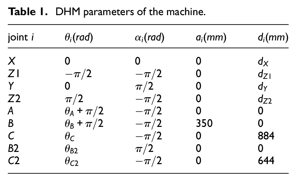
Figure 3 shows the coordinate frames of the fiber placement system.
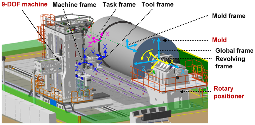
Coordinate frames of the fiber placement system.
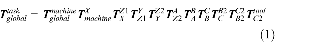
The forward kinematic problem (FKP) describes the tool frame (the frame fixed on the roller of the machine head) as a function of joint coordinates. The FKP of the machine can be obtained by chain multiplication:
In order to ensure accurate placement and sufficient compressive force, the roller must be precisely oriented for the mold surface. Therefore, the following relationship needs to be satisfied (see Figure 4):

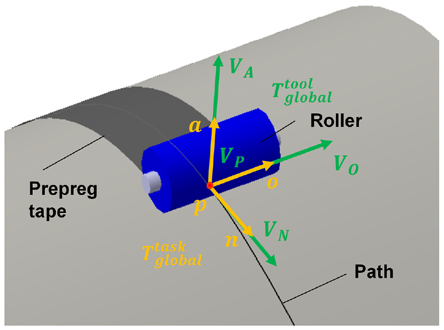
Orientation of the roller relative to the surface.
In Figure 4,
Since mold rotating with positioner,

where
Axis assignment schemes of 9 DOFs machine
The 9 DOFs machine has four translational joints and five rotational joints. One DOF is reduced by the equal distribution of the translational joints
There is a total of
The
Seven axis assignment schemes.
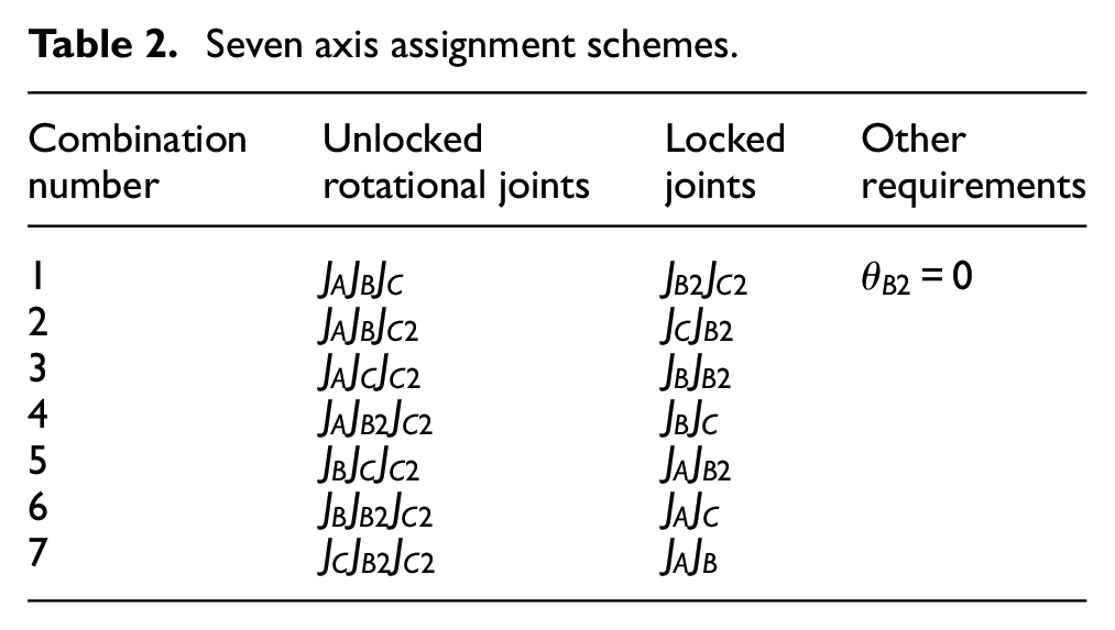
There is duplication scheme in the Table 2. The duplication judgment is first given: If the workspace (including orientation space and position space) of scheme A is exactly the same as one of the machine types contained in scheme B. Thus, scheme B covers the case of A, and A is excluded as a duplicate scheme.
Axis assignment schemes.
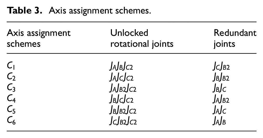
Figure 5 shows the kinematic models of the rotational joints for the different machine types. The actual linkage of the non-redundant machine is represented as the solid black line.
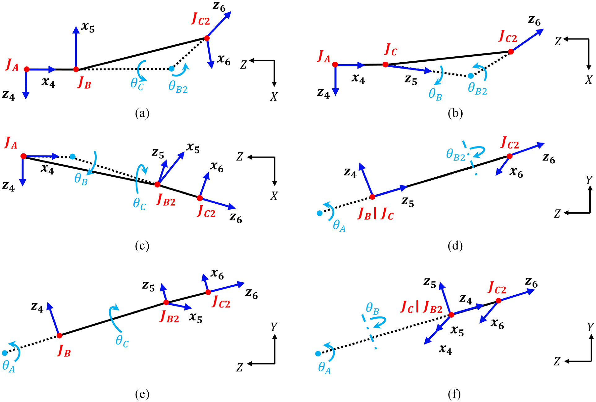
Kinematic models of rotational joints for different machine types: (a) C1, (b) C2, (c) C3, (d) C4, (e) C5, and (f) C6.
The definition of the global and local indices
Different machine types have diverse kinematic chains and therefore differ in performance indices. In this section, the global and local performance indices are proposed.
Global performance indices
Global indices are posture-independent indices representing the manipulator workspace’s global characteristics. They have only one value for a given manipulator workspace. Global indices are essential for evaluating different machine types. This subsection will introduce the calculation of three global indices: dexterity index, global manipulability index, and global conditioning index.
Dexterity Index
The dexterous workspace of a manipulator means that for any point in that space, the manipulator’s end-effector can reach that point in any direction (
As can be seen from Table 3, since all axis assignment schemes have the unlocked joint
As in Figure 4, the

where
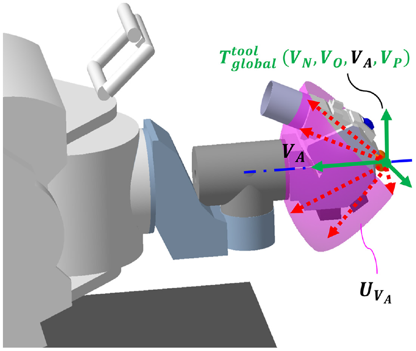
The normal vector space of the machine type (The solid line is the current tool frame, and the fuchsia area is the normal vector space).
We decompose the three-dimensional (3D) vector into two-dimensional (2D) coordinates. Then, the total space is discretized on the

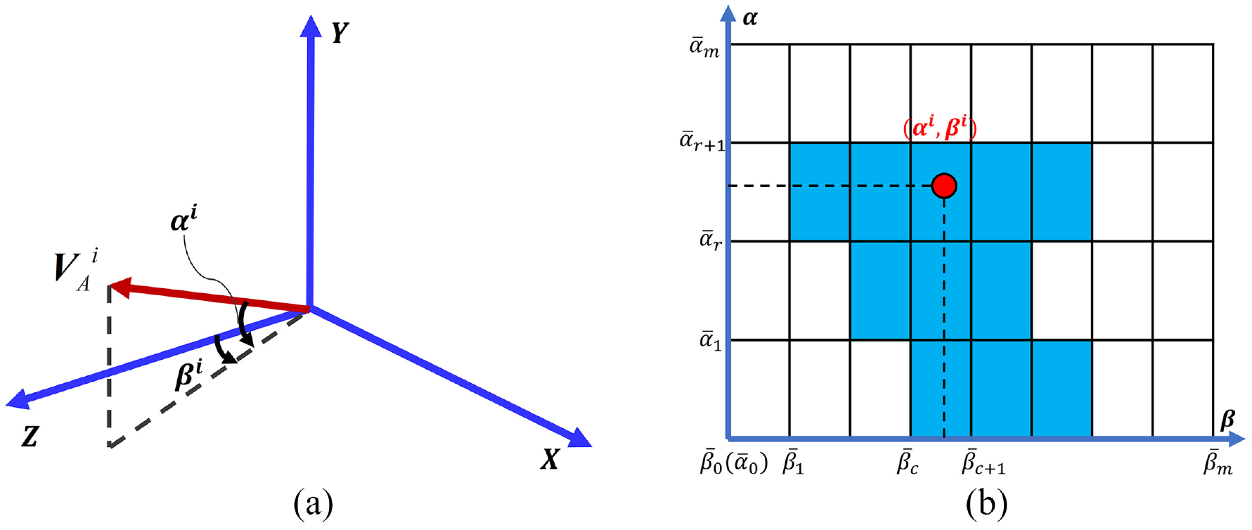
Calculation of dexterity index: (a) normal vector decomposition and (b) dexterity index calculation grid (blue is the occupied grid).
If the grid is occupied, the area represented by the grid is reachable. All the grid numbers form an array
However, the total space is discretized in 2D with step
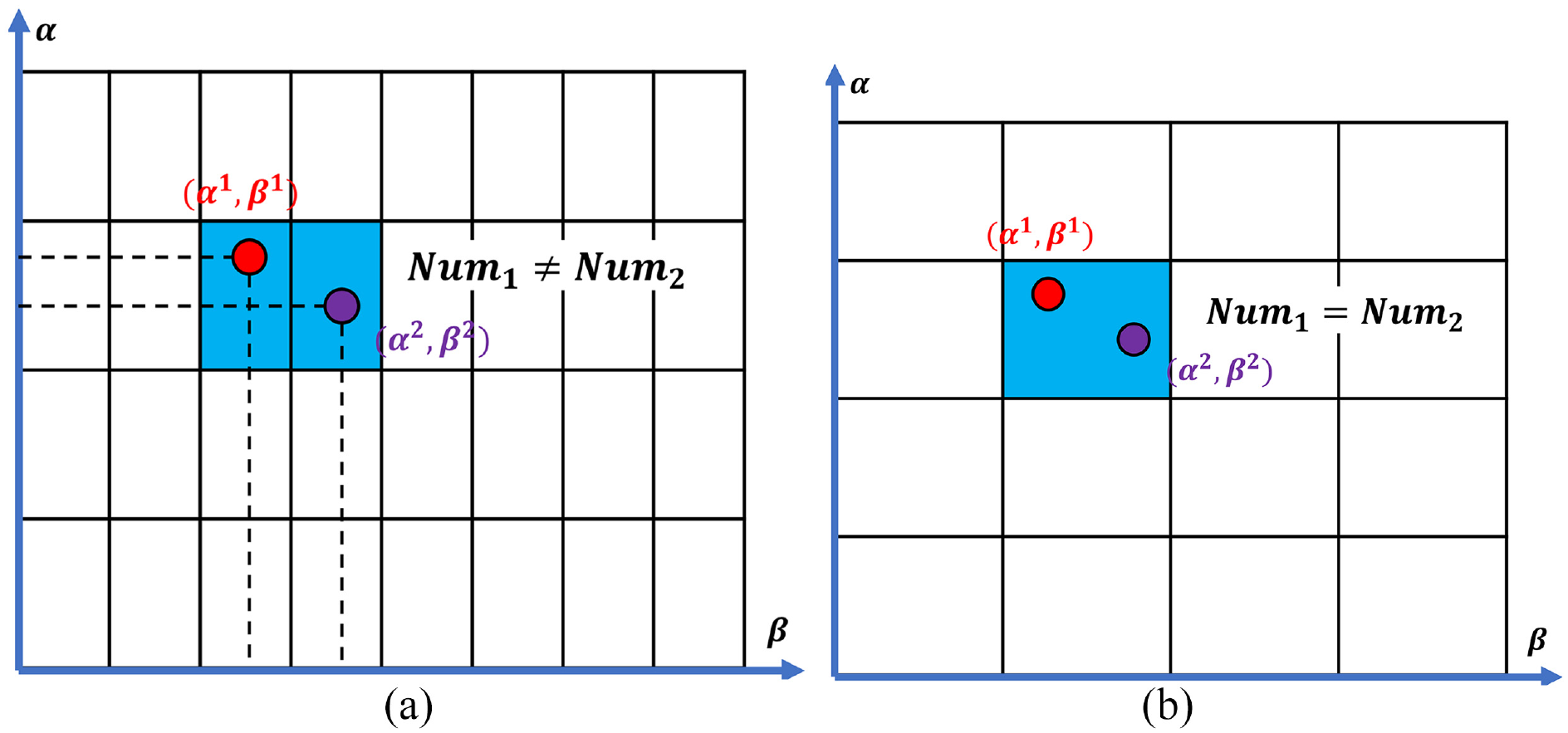
(a) Two elements occupying one grid each (no duplication) and (b) two elements occupy one grid (duplication appear).
As a result, this grid number is added repeatedly to the array
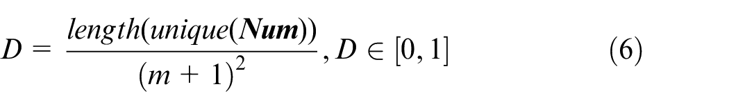
where
Global Manipulability Index
The Global Manipulability Index (GMI) is built based on the manipulability index. The manipulability index is a kinematic performance index proposed by Yoshikawa, 4 which considers the end-effector’s motion in all directions and helps estimate the overall sensitivity and dexterity of the manipulator to actuator displacement. The normalized manipulability index is defined as:
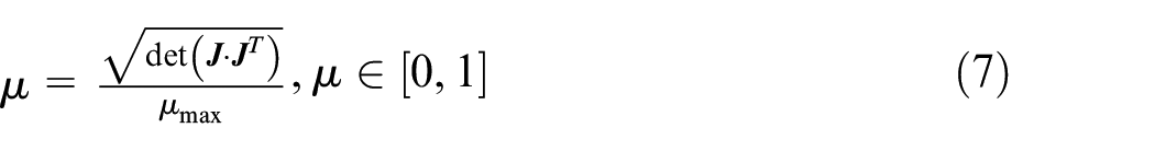
where
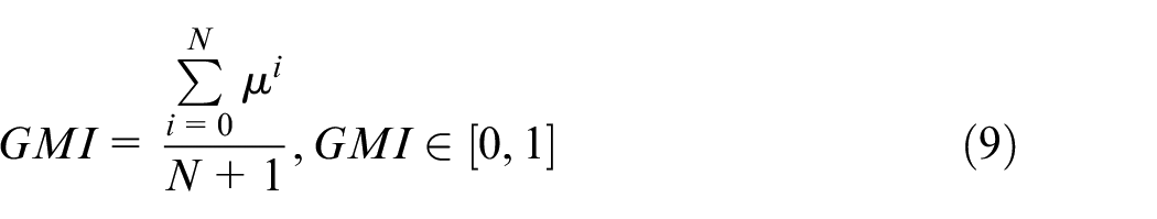
The GMI is defined as the ratio of manipulability index over entire workspace to the workspace’s size, given by,
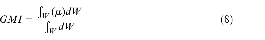
where W is a point in the manipulator workspace, and
The manipulability index is based on the Jacobi matrix and independent of the translational and
Global Conditioning Index
The Global Conditioning Index (GCI) is a condition number-based index. Salisbury and Craig introduced the condition number as a kinematic performance measure. 28 The condition number is a measure of the isotropy of the Jacobi matrix, which better reflects the manipulator’s ill-conditioning degree. It is a good measure of the kinematic accuracy and the distance from the singularity of the manipulator. 29 It is defined as the ratio of the maximum singular value to the minimum singular value of the Jacobi matrix.
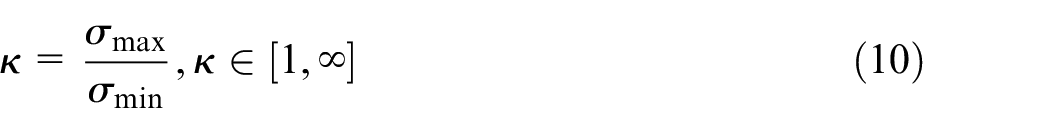
Since the machine has both translational and rotational joints, the concept of characteristic length proposed by Angeles 30 is used to solve the Jacobi matrix’s resulting dimensional non-homogeneity problem. The last three rows of the Jacobi matrix representing the position are divided by the characteristic length L to obtain dimensionless homogeneous Jacobian for the calculation of equation (10).
The manipulator configuration with unit condition number is called isotropic configuration. When the Jacobi matrix loses full rank, that is, singularity, the minimum singular value is zero, and the condition number is infinite.
The GCI, proposed by Gosselin and Angeles, 31 shows the distribution of the condition number across the workspace. The discrete formula for the GCI is
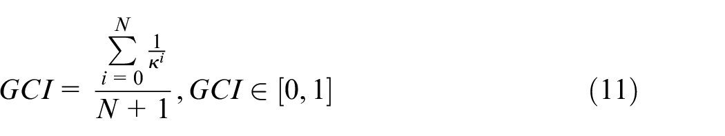
where N is the total number of discrete vectors in the normal vector space, and
Axial local performance indices
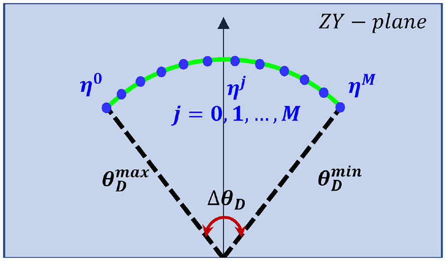
In this paper, a non-redundant machine is determined before the mold rotation trajectory is planned, so the machine’s performance evaluation considers its own global performance and the positioner-driven mold rotation effect. The mold rotates with the positioner, and its normal vector needs to enter the machine’s normal vector space to satisfy the reachability. The normal vector space determines the admissible rotation range. In order to describe machine performance within this rotation range, axial local indices are proposed, including joint range availability, axial minimum singular value, axial manipulability, and axial condition number indices.
Joint range availability
Mapping the machine’s normal vector space
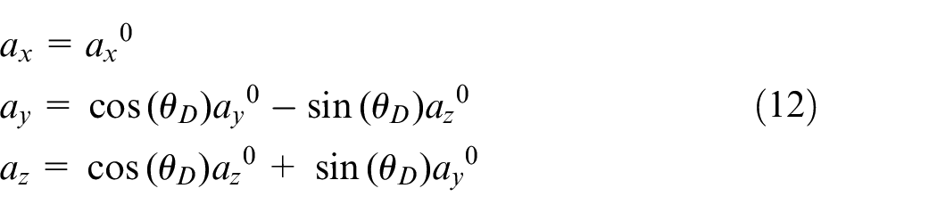
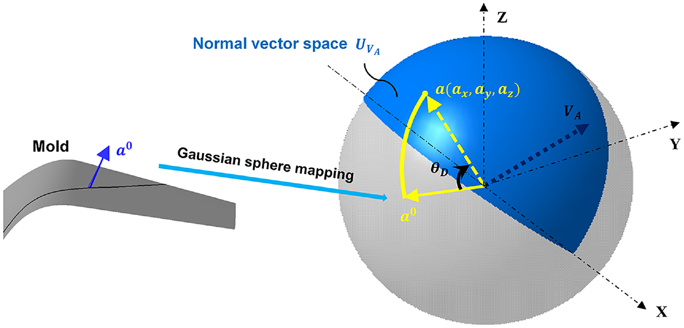
Normal vector mapping and vector rotation.
When
When the reachability constraint is satisfied,

where
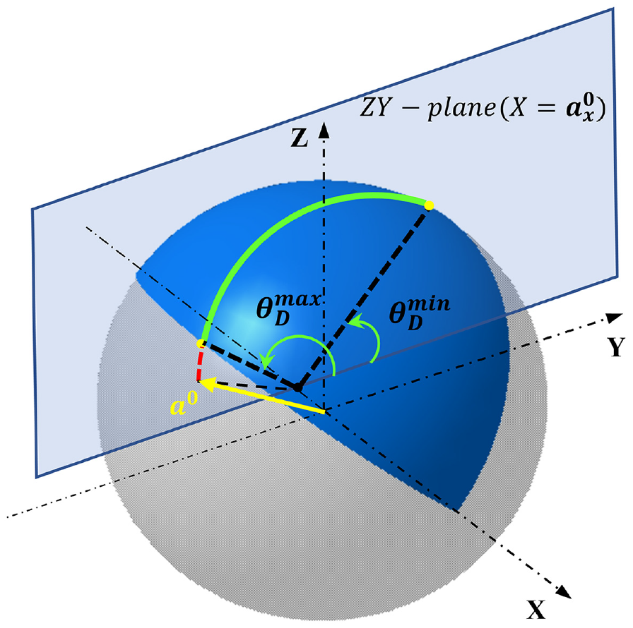
Admissible rotation range of the positioner.
We define
Therefore, we propose the Joint Range Availability (JRA) index to judge the magnitude of the positioner rotation angle that satisfies a vector reachable in the machine workspace, defined as
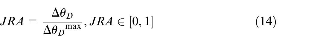
where
The JRA index describes the magnitude of the redundant joint space for subsequent motion planning. Also, it represents the gain in motion flexibility resulting from the reduction of the 10 DOFs system to 7 DOFs. The larger the JRA index is, the bigger the redundant space for the 7 DOFs layup system.
From Figure 10, the JRA of a set of normal vectors with the same X coordinates are the same. Therefore, it changes along the mold rotary axis. We call this distribution of indices a local axial index. The other axial indices in subsection 3.2.2 will also be expressed.
Axial kinematic performance indices
In order to analyze the machine kinematic performance level in the admissible rotation range, the other axial local performance indices are proposed.
First, the Minimum Singular Value (MSV) is a performance index proposed by Klein and Blaho. 32 Its essence is the minimum singular value of the Jacobi matrix. The MSV represents the minimum transmission ratio, maximum force transfer, and maximum accuracy. Yoshikawa 33 interpreted MSV as an upper bound on the speed at which the manipulator can move in all directions. The MSV was normalized using equation (15)
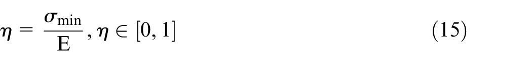
where
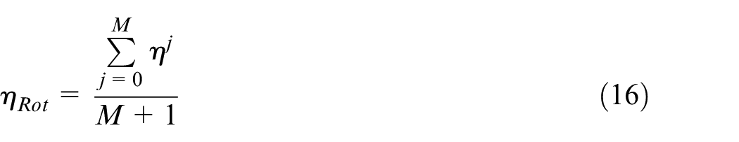
where
Schematic of axial MSV index.
Similarly, the axial manipulability index is defined as
The axial condition number index is defined as
Redundant resolution for the 9-DOF machine
This section proposes a method to solve the redundancy problem of 9-DOF machine based on the global and local indices presented in Section 3. The method consists of three parts: Firstly, refine the machine types of each axis assignment scheme based on the average global indices. Then, select the best axis assignment scheme by comparing the scheme’s local indices for a given mold. Finally, optimize the non-redundant machine type contained in the optimal scheme with the objective of superior local indices and continuous positioner rotation space.
Refinement of machine types based on global indices
In an axis assignment scheme, the machine types have the same locked joints but different locked angles. Therefore, their global index values differ within the same scheme. The locked angles of each scheme are discretized, and Figure 12 gives the maps of the dexterity index D, global manipulability index GMI and global conditioning index GCI(Figure 12) concerning the locked angles.
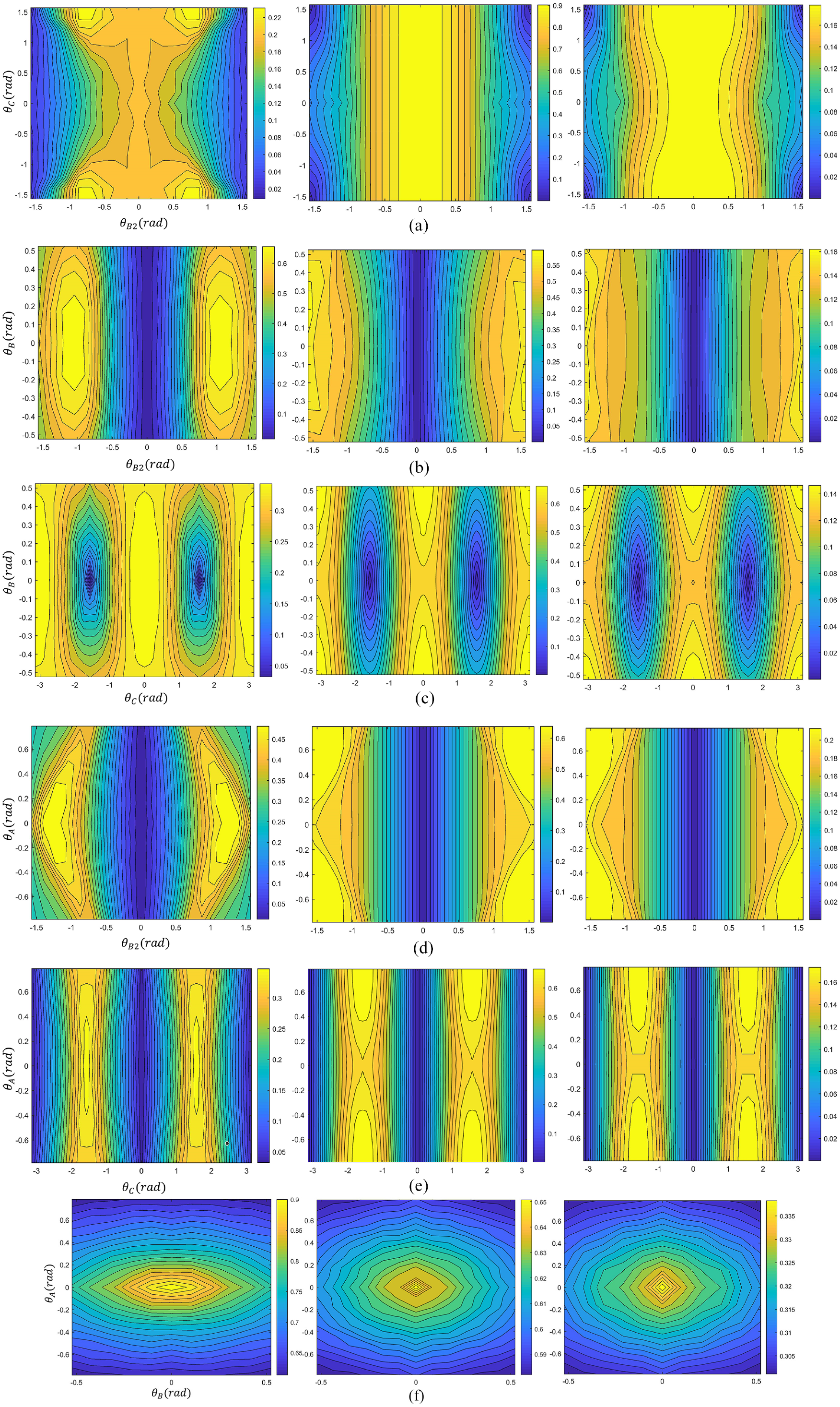
Distribution of global indices within the schemes (from left to right, index D, GMI, GCI): (a) C1, (b) C2, (c) C3, (d) C4, (e) C5, and (f) C6.
Refinement of machine types is achieved by eliminating machine types with very low global index values, and those that remain are the feasible types. The threshold value is the average of all machine types’ global index, as shown in Table 4.
Average of three global indices.
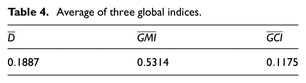
From Figure 12, it can be seen that the distribution of indices has a specific pattern under the same scheme. Thus, the feasible machine types in the same axis assignment scheme can be delineated by the locked angles, that is
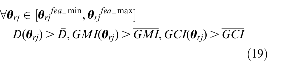
where the minimum feasible angle of the redundant joints is
Comparison of axis assignment schemes based on local indices
For a non-redundant machine to process a rotating mold without determining the mold rotation trajectory, it is necessary to know the distribution of the machine’s performance in the direction of the mold rotary axis, that is, the axial local indices mentioned in Section 3.2. We will calculate the local indices of every scheme in order to examine its superiority and thus obtain the optimal axis assignment scheme.
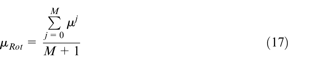
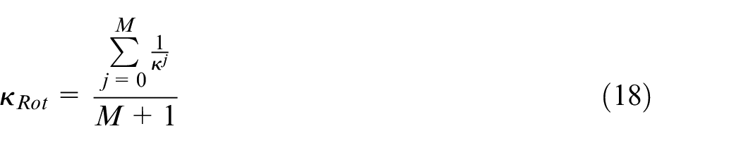
Assuming the number of the discrete machine types in a scheme is
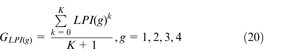
where
Along the mold rotary direction (X-axis), the calculated local index values
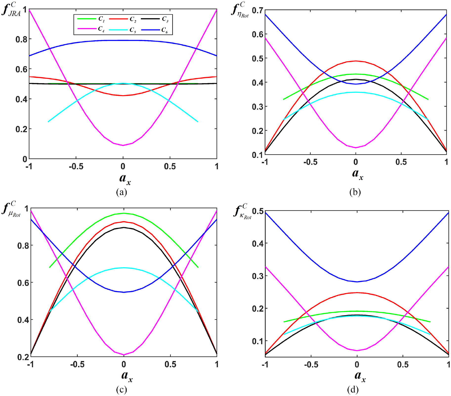
Local performance index distribution curves of the schemes: (a) Joint Range Availability (JRA), (b) Minimum Singular Value (MSV), (c) Manipulability index, and (d) Condition number index.
As shown in Figure 13, the local indices differ significantly among the schemes in different coordinate value intervals. For example, in the interval [0.7, 1], the
Another example is that in the interval [−0.5,0.5], the
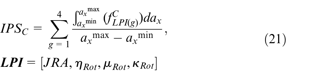
Moreover, in order to obtain the best scheme, the comparison function is established:
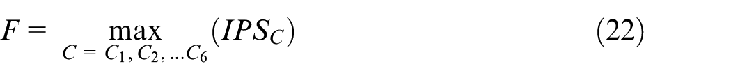
Therefore, using equation (22) can obtain the optimal scheme.
Optimization of the machine type within optimal scheme
After preferring the optimal axis assignment scheme, this subsection addresses optimizing the machine type within the preferred scheme, that is, optimizing the locked angle. Taking a fiber placement path as an example, the method for optimizing the machine type in the optimal scheme is as follows.
Assuming that the path normal vector sequence is
Consequently, the first objective of the locked angles optimization problem can be written as equation (24):

Another index evaluates the positioner’s admissible joint space’s continuity when laying up a given path. The more continuous it is, the more friendly to the motion planning and system control. It is defined as equation (25):
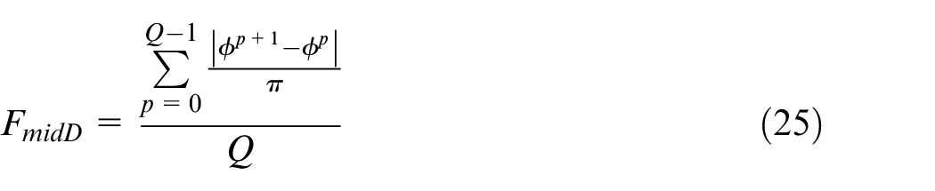
where
Accordingly, the second objective of the optimization problem can be written as equation (26):

Therefore, once the locked angle
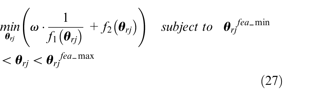
where
Experimental validation
Air inlets are a class of composite parts in the aerospace field whose surface normal vectors vary drastically in the vertical plane of its rotation axis. It is often necessary to use a positioner to rotate the air inlet to assist the machine in fiber placement. The air inlet model studied in this paper is shown in Figure 14(a). The model has
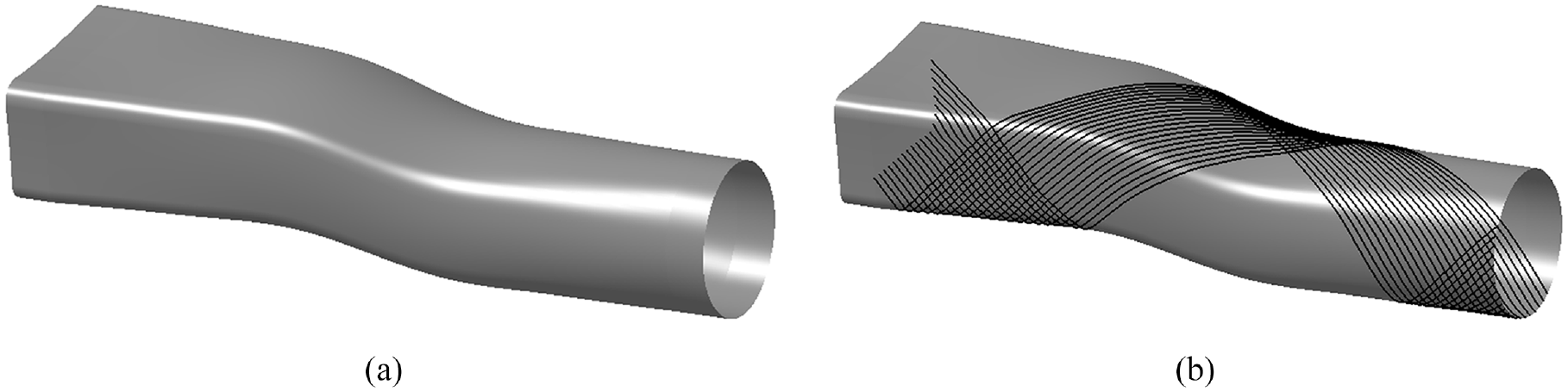
Air inlet mold: (a) mold surface and (b)
The 45° placement path is shown in Figure 14(b). The simulation model of the fiber placement system is shown in Figure 15. The process of redundancy resolution for a 9 DOFs machine is introduced with the air inlet model as an example. Then, two existing methods are used to plan the rotational trajectory of the mold. Finally, the motion of each motion joint and layup speed is compared between the optimal machine type and the other two machine types.
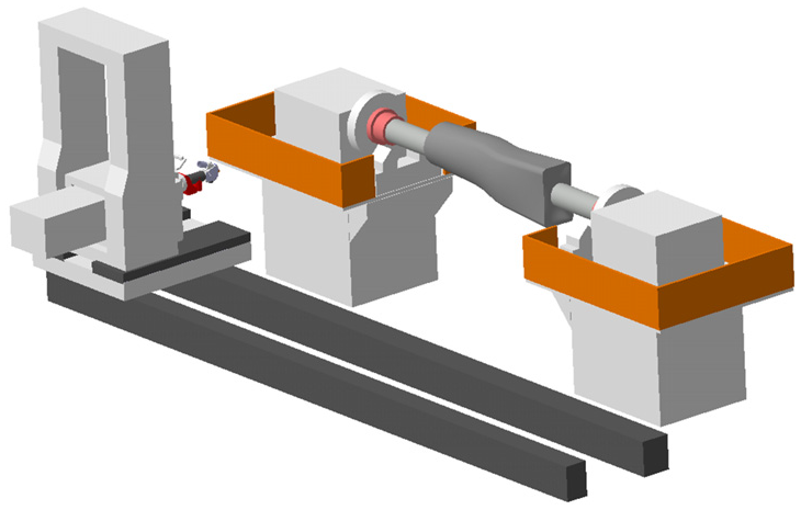
Simulation model of the fiber placement system.
Determination of the optimal machine type
Firstly, according to the data of the path point frames
By equation (21), the scheme’s local performance indices in
The local performance indices of all schemes in
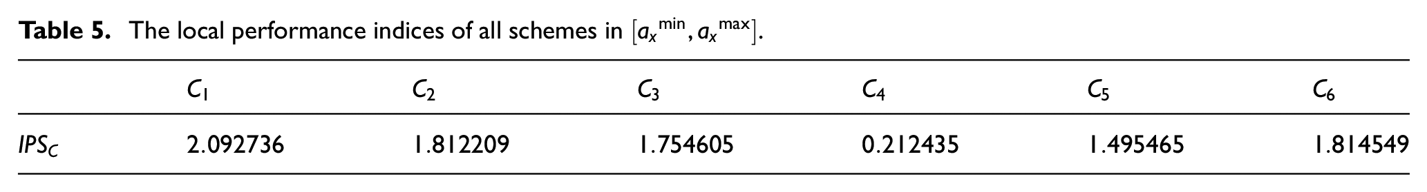
The redundant joints of the
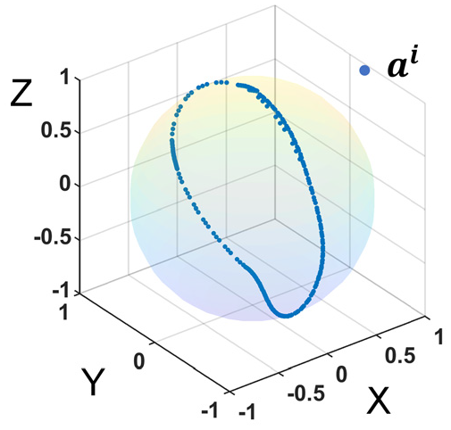
Normal vector mapping.
The relevant parameters of the genetic algorithm are set as follows:
Population size = 300,
Maximum number of genetic generations = 500,
Crossover rate = 0.75,
Boundary variation = 0.004,
Interval migration = 10,
Migration fraction = 0.1.
It is worth noting that the selections of the appropriate control settings result from extensive experimental efforts, and various control schemes were employed according to the instructions in the literature. The initial solution is
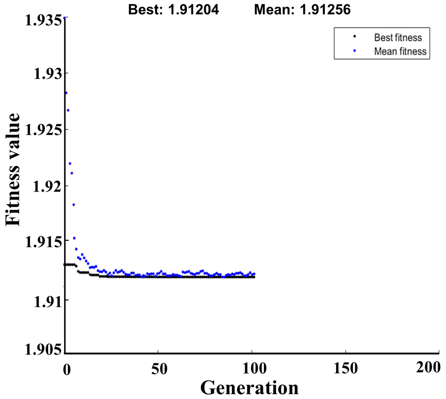
Genetic algorithm convergence process.
Analysis of the effect of machine type on the performance of the fiber placement system
This subsection will verify the collaborative capability of the optimal machine type. Two existing methods are used to plan the motion trajectory of all system joints (non-redundant machine and positioner). One is based on the shortest distance method mentioned in Gao et al., 14 which indicates that the acceleration is expressed in discrete from and used as a constraint, the maximum velocity of each joint is used to calculate the minimum time. Then, dynamic programing algorithm is proposed to find the time-optimal positioner motion trajectory for the whole path. Another method is to take into account the larger size or weight of the mold, resulting in a more giant load on the positioner. In this case, the mold rotation is required to be as smooth as possible, so the positioner rotation trajectory is separately smoothed based on the first method. Finally, the effectiveness of the proposed method is verified by analyzing the motion of each joint and the layup speed.
The optimal machine type is known as scheme
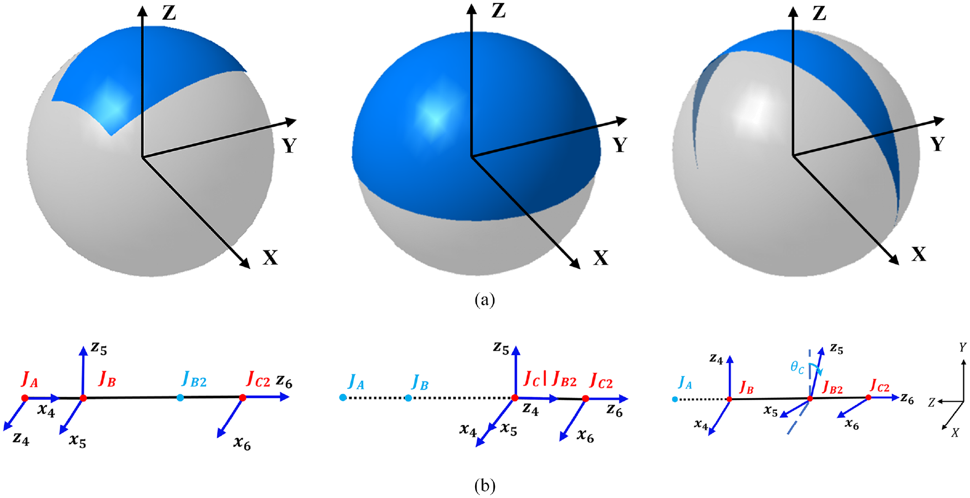
The normal vector space and kinematic models of three machine types (from left to right are
To better demonstrate the difference between the three machine types, Figure 19 gives the four axial local performance along the path.
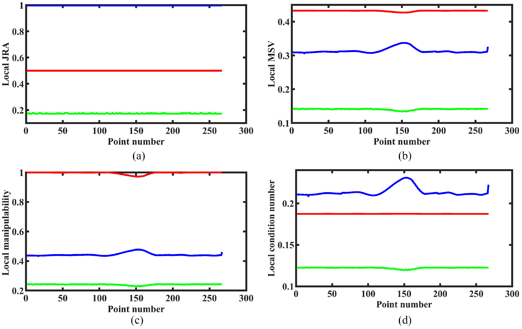
The local performance of three machine types along the path: (a) Joint Range Availability (JRA), (b) Local Minimum Singular Value (MSV), (c) Local Manipulability, and (d) Local Condition number.
From Figure 19, the optimal type
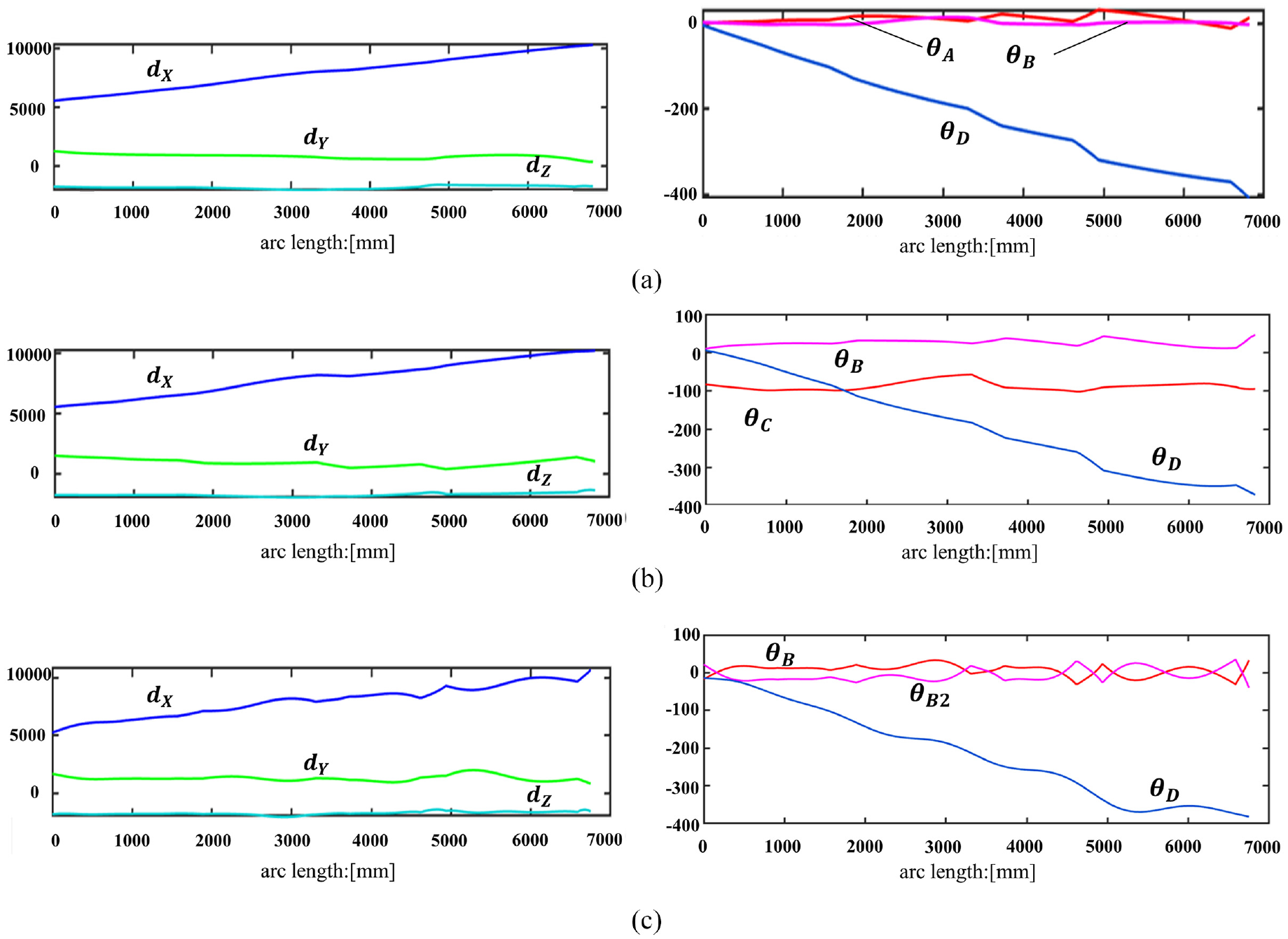
Joint coordinate profiles: (a) MTopt, (b) MT2, and (c) MT3.
Set the feed speed F =
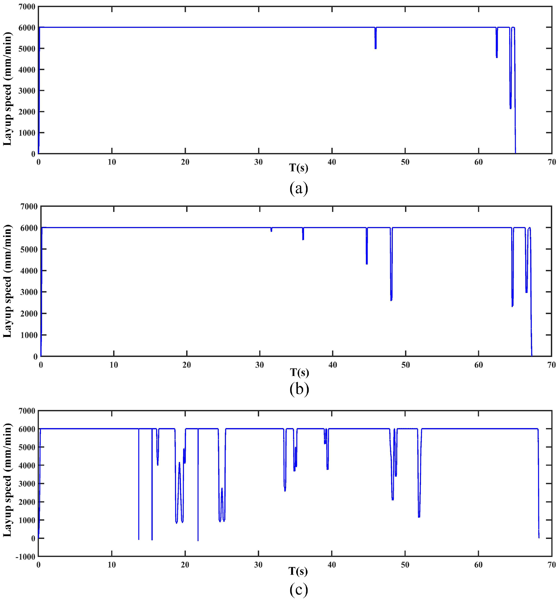
Layup speed profiles: (a) MTopt, (b) MT2, and (c) MT3.
As seen in Figure 20(a) and (b), the joints are smoother for
We can analyze the reasons for the above phenomenon from Figure 19. For
The joint trajectories of the three machine types after smoothing are shown in Figure 22:
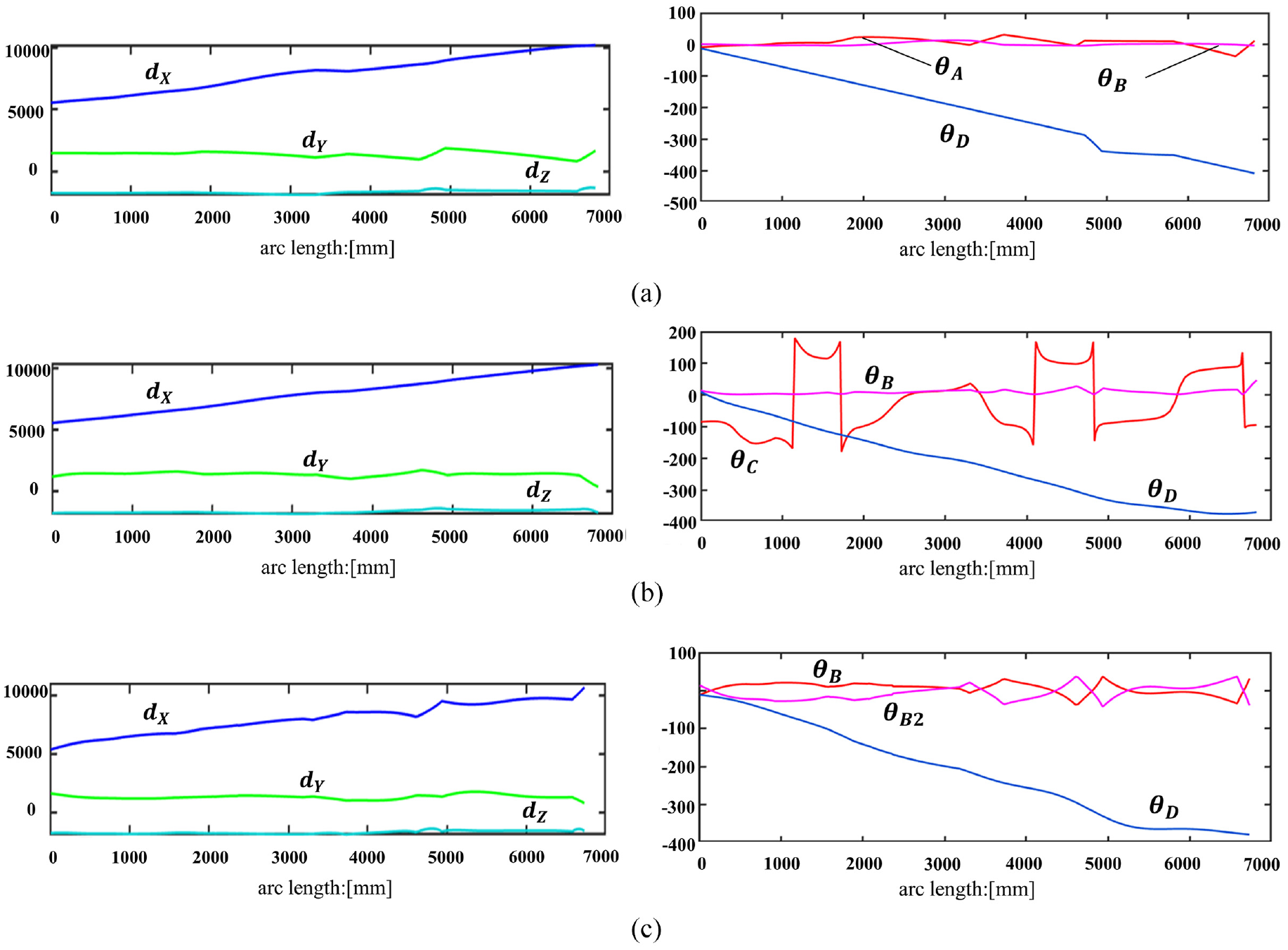
Joint coordinate profile after positioner angle smoothing: (a) MTopt, (b) MT2, and (c) MT3.
The simulation results of layup speed are as follows (Figure 23):
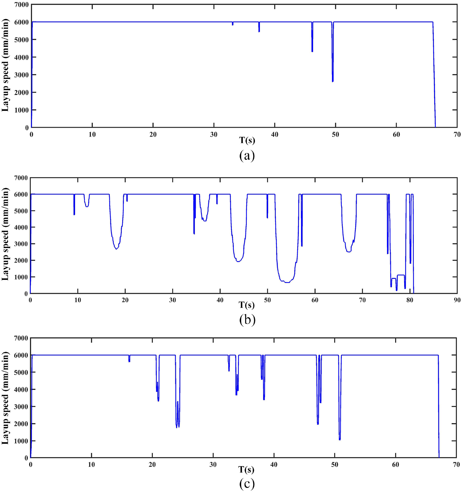
Layup speed profiles after positioner angle smoothing: (a) MTopt, (b) MT2, and (c) MT3.
As seen from Figure 22,
Comparing the results of the two motion planning methods, laying the air inlet’s
The final smoothing results of
The
Conclusion
This paper proposes a new redundancy resolution method for the hyper-redundant machine that lays molds rotated by a positioner through synthesized global and local performance indices.
The method reduces the 9 DOFs machine to a 6 DOFs non-redundant structure by locking rotational joints. In order to evaluate different machine types, the definitions of global and axial local indices are given first. The difference between the two kinds of indices is that the global indices evaluate the performance of the whole normal vector space of the machine. In contrast, axial indices assess the performance and the magnitude of the rotation space along the mold rotary axis. These indices evaluate the kinematic performance and motion flexibility of the machine.
The method has three steps: Firstly, refine the machine types for each scheme according to the average global indices. Then, calculate the local indices distribution curves of different schemes, and compare the scheme’s local indices for a specific mold to select the best scheme. Finally, optimize the machine type to improve the local indices and the continuity of positioner rotation space for a path.
The method optimizes the machine type based on the reduction of the DOFs. This strategy is more efficient than planning the motion of multiple redundant joints altogether. Moreover, the global and local indices proposed fully consider collaborating with the positioner, which ensures the optimized non-redundant machine has a high-performance and sizeable flexibility space for the subsequent motion planning.
Finally, using the
Footnotes
Declaration of conflicting interests
The author(s) declared no potential conflicts of interest with respect to the research, authorship, and/or publication of this article.
Funding
The author(s) disclosed receipt of the following financial support for the research, authorship, and/or publication of this article: This work is supported by the National Natural Science Foundation of China [No. 52105535].