
Abstract
Hyper-redundant robots, robots with many degrees of freedom, are considered to be advantageous in many tasks, such as minimally invasive surgery, surveillance and inspection. However, due to their hyper degrees of freedom, the control of hyper-redundant robots is always challenging. Several fitting algorithms, which iteratively fit a hyper-redundant robot into a continuous curve, have been proposed to control the configuration of hyper-redundant robots. However, these algorithms require heavy computation, preventing them from being used in practice. In this study, we propose a novel modular control scheme for a hyper-redundant robot to reduce the computational load by dividing the robot into smaller modules and fitting each module separately. A Jacobian-based position control algorithm is also used to utilize the redundancy of each module to ensure that the overall configuration of the robot resembles the given desired curve. Simulation results show that the proposed scheme can be used to control hyper-redundant robots effectively.
Introduction
There has been much study devoted to the hyper-redundant robot, which is a robot with lots of redundant joints. Redundancy improves the dexterity and the robustness of a robot [1] and thus, it is expected that hyper-redundant robots would show better performance than conventional robots, especially in an unstructured environment. For this reason, many hyper-redundant robots have been developed for tasks such as minimally invasive surgery [2–4], surveillance [5] and inspections [6]. However, the practical application of hyper-redundant robots has been limited because the control of a hyper-redundant robot requires all active joints to be controlled in a systematic way to create a well-defined task motion. Often, the pseudoinverse of Jacobian is used to control a redundant robot, which allows the robot to utilize the redundancy to achieve a secondary goal, such as avoiding an obstacle [7], joint limits [8, 9] and kinematic singularity [10]. However, these Jacobian-based methods are intended for a robot with one or two additional degrees of freedom (DOF) and they cannot be used to control a hyper-redundant robot. Furthermore, these methods cannot effectively control the overall configuration of a hyper-redundant robot, which is often desired.
There has been much research done on the control of hyper-redundant robots. These algorithms focus on expressing the desired posture of the robot as a backbone curve, and controlling the robot to resemble the created curve. A modal-based approach was introduced to control a hyper-redundant robot effectively [11], but that method is limited to a planar robot. A solution based on the shape Jacobian was also proposed to control the shape of a robot [12]. However, the solution is limited to a robot with two DOF revolute joints. A shape estimation method using an extended Kalman filter and an electromagnetic sensor was proposed [13], which is applicable if and only if the robot is controlled by a follow-the-leader algorithm.
On the other hand, fitting algorithms, which iteratively fit the configuration of a hyper-redundant robot into a continuous backbone curve, are also widely studied in order to control hyper-redundant robots. Fitting algorithms are often preferred as they can better reflect the discrete structure of hyper-redundant robots. A fitting algorithm, which approximates the backbone curve by piecewise line segments, was introduced [14], but the algorithm is only applicable to a robot with universal joints. Another algorithm, which can be used on a hyper-redundant robot of any joint configuration, was introduced [15]. A fitting algorithm with reduced computational load was also introduced in [16], which is also limited to robots with universal joints.
However, while these algorithms can be used to control a hyper-redundant robot, the required computational load is still too heavy for practical uses, especially if the robot has many redundant DOF. It was found that to improve the performance of the fitting algorithms, the required computational load must increase exponentially [15]. Another concern with fitting algorithms is that they focus on controlling the configuration of hyper-redundant robots and they cannot be used to place the end-effector of the robots at the desired position. However, since many hyper-redundant robots perform tasks using tools at their end-effectors, its end-effector positioning accuracy must be guaranteed.
In this study, in order to reduce the computational burden of fitting algorithms, we propose a novel control scheme to distribute the computational load among multiple controllers. The scheme divides the robot into modules and applies a fitting algorithm and a Jacobian-based position control algorithm. The fitting algorithm ensures that the configuration of the robot resembles the desired curve while the position control algorithm utilizes the redundancy of each module to enable parallel computation. The advantages of the proposed scheme are as follows. First, the scheme is computationally efficient, as each controller only has to fit the assigned module. Second, the scheme is not restricted to a robot with a certain joint configuration. Lastly, by using the position control algorithm, the end-effector accuracy can be guaranteed. A similar concept for a hyper-redundant robot was proposed in [17], but the study aimed to remove the redundancy of each module. In contrast, the proposed scheme focuses on utilizing the redundancy to enable parallel computation.
Modular Control Scheme
Controller Configuration
To enable modular control, a given desired backbone curve must be divided into smaller segments for each module. Two types of controllers are involved in this scheme: the main controller and the module controllers. The main controller is in charge of dividing the curve and assigning it to each module. Then, each module is fitted to the assigned segment by its module controller. Following the fitting, a Jacobian-based position control algorithm is used to adjust each module so that the resulting configuration of the robot resembles the given backbone curve. The overall flow of the proposed scheme is illustrated in Figure 1 and a detailed explanation of each step will be given in the following sections.

Proposed control scheme and role of each controller
We first assume that a desired backbone curve is given as a point set pd (·). Many studies have been devoted to how to create a backbone curve for a hyper-redundant robot, such as [18–20], and we will not discuss them here as they are beyond the scope of this study.
Assuming the robot consists of m modules, m segments are required. Thus, the main controller divides the given point set pd (·) into m segments. Note that each module is connected in a series and thus, for parallel computation, each module must be able to completely cover the assigned segment. This cannot be done if the given segment is longer than the length of the module. Therefore, the following condition is used to divide the given backbone curve:

where lm is the length of the module, p is the total number of points in the given backbone curve and ∈ is the predefined threshold. This ensures that the total length of the segment is shorter than the length of a module. A special case for the segmentation would be the case when the length of the given backbone curve is shorter than the length of the hyper-redundant robot. In such a case, only parts of the robot will be controlled to resemble the backbone curve while other parts remain uncontrolled.
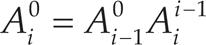
To enable parallel computation, the start and end position and orientation of each segment must be specified. This is due to the fact that all the modules are fitted at the same time, and the end position and orientation of module j serves as the starting position and orientation of module j +1. Therefore, each segment must include six constraints: three in position and three in orientation. This can be done by attaching a frame coordinate at each end of the segment, as shown in Figure 2. Each segment and its constraints must also be expressed in the base coordinate of the module to allow independent computation. Thus, once segment j is found using Eq. (1), we must represent it with respect to frame j−1, as it is currently expressed in frame 0. It can be done by multiplying the computed segment by
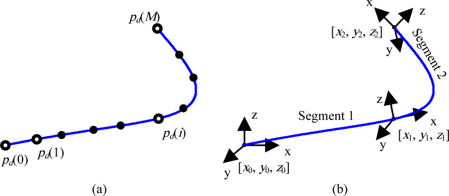
Segmentation of the backbone curve: (a) given backbone curve, and (b) segmentation and attached frames
Once the segmentation is completed, the main controller will send the rotated segment and the six constraints to each module controller, and this complete the task of the main controller. The module controller will actually control each module so that the robot can follow the desired curve.
The data about the segment and its six constraints are provided to each module controller, so that the module controller can perform actual fitting. It was found that fitting multiple joints at the same time yields a better result, but at the cost of a much higher computational load. This coincides with the result presented in [15]. Once the number of joints to be fitted simultaneously is set, we perform bracketing, which coarsely finds the set of backbone curve points to be used to optimize the set of joints. This is done so that the controller does not have to perform the optimization over the entire segment. Bracketing is similar to the algorithm for dividing the curve into segments:

where lk is the length of the part of the module to be fitted at the same time and ps is the number of points in a segment. Then, the following optimization rule is used:

where X is the distal-end position of the module, qmin and qmax are the minimum and maximum joint angles, respectively, and pi and pe are the starting and end points of the bracketed segment. Note that the sum of the squared distance is used as the objective function. This optimization minimizes the distance between the given backbone curve and the distal end of each link of the module, so that the module resembles the given segment. In addition, as can be seen from Eq. (3), the algorithm is computationally demanding, and the computational load increases as the number of joints to be fitted increases.
It is important to note that using the fitting algorithm described above, the final position and orientation of the end-effector of each module cannot be controlled. Thus, to satisfy the imposed six constraints, an additional position control algorithm is required.
After running the fitting algorithm, we obtain a set of joint angles that allows the configuration of the module to best resemble the shape of the segment. However, the position and orientation constraints are not yet satisfied. To deal with this, we added position control to the control scheme. A Jacobian-based position control is used, as a Jacobian can be easily found in a systematic way, whereas an inverse kinematics solution is configuration-dependent and often hard to obtain. In addition, by using a Jacobian, we can easily utilize redundancy, which is crucial in the proposed control scheme. Redundancy provides an infinite number of inverse kinematic solutions. Thus, among the infinite solutions that satisfy the six constraints, we search for the one that is the closest to the set of joint angles given by the fitting algorithm. In other words, we use the result from the fitting algorithm as the starting point and adjust it to meet the six constraints while minimizing the change at each joint, so that the overall posture of the robot can be preserved. This implies that each module must consist of more than six joints, and that each module is treated like a redundant robot.
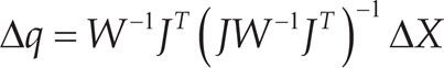
A pseudoinverse Jacobian has been widely used to control redundant robots. In order to utilize the redundancy to achieve a secondary goal, the gradient projection method and weighted least-norm have also usually been adopted. In this study, we used weighted least-norm, as it does not require gain tuning which has to be found by trial and error, and it minimizes the self-motion [9]. Assuming a hyper-redundant robot of n-DOF, which consists of modules of nm-DOF, the weighted least-norm solution can be represented as:

where
where ΔX would be the error between the current position of the distal end of the module and the constraints in position and orientation. As stated in previous sections, each module controller is given the six constraints. The position part of ΔX would simply be the position error between the distal end of the module and the end position of the segment. As for the orientation, unit quaternion is used in this study to avoid any representation singularities [21]. This allows hyper-redundant robots to move towards any arbitrary direction. Rotation matrix
The weighting matrix W can be expressed as:

where wi, the i-th element of the diagonal matrix W, is defined as

where H(q) is the desired performance criterion. The user can set up appropriate ∂H(q)/∂qi to achieve the desired secondary goal and it can be seen from Eq. (7) that if ∂H(q)/∂qi decreases, wi will become 1 and there will be no null space motion. In this study, the goal is to minimize the deviation of the fitted angles from the fitting algorithm, and thus, the objective function is set to:

where qi,fit is the result from the fitting algorithm. As can be seen from Eq. (8), the function is equal to zero when the angle is at the fitted position, and it increases rapidly as the joint moves away from the fitted position. Thus, as a joint angle qi deviates from the qi,fit, this function will cause a reduction in the motion. With this redundancy utilization, we can satisfy the constraints in the position and the orientation while keeping the configuration of the module as close as possible to the fitted result.
As we use the fitted solution as the starting point, it is important to obtain a good starting point. As mentioned above, to obtain a good fitting result, one must fit several joints at the same time (increase k in Eq. (2)). This would increase the computational load. However, with the modular control scheme, the burden of each controller is lessened and thus, the controllers can fit multiple joints at the same time, which would not have been possible using a single controller.
As stated in previous sections, if a hyper-redundant robot is to perform a task it must be able to place its end-effector accurately at the desired location. This can be easily accomplished using the proposed position control method shown in Eq. (5). It would allow the user to control the last module to move the end-effector while minimizing the change in the overall configuration of the robot. Thus, the proposed control scheme not only reduces the computational load, but it also increases the efficiency of the robot.
It should be noted that the proposed algorithm is not limited to a certain joint configuration, and the corresponding Jacobian for any hyper-redundant robot can be easily solved to apply the proposed control scheme. Thus, the proposed algorithm is highly flexible and can be applied to any hyper-redundant robot.
Robot
A 24-DOF robot with alternating yaw and pitch joints was simulated using MATLAB (MathWorks, Inc., Natick, MA). We chose the configuration with the alternating joints since this configuration is widely used in many hyper-redundant robots, such as [22,23]. To enable the proposed modular control, the robot was divided into three modules of 8-DOF each, and a module is shown in Figure 3. The length of each link is set to 1.5 unit length, and ∈ in Eq. (1) is set to 0.05. qmin and qmax are set to −70 and 70 degrees, respectively, and (for optimization) the angle increments by 5 degrees. For a better result, we fitted two joints at the same time.

Joint configuration of a module
Two Bezier curves were used as the desired backbone curve for the simulation. Bezier curves are often used to simulate a backbone curve for a hyper-redundant and they can be described as [14]:
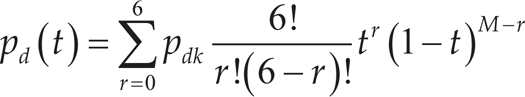
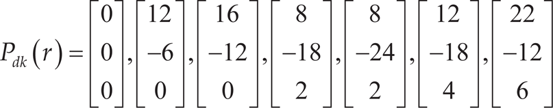
with seven control points, Pdk and M is equal to 6.
The simulation was conducted using a single PC, although the proposed scheme involves the use of multiple controllers. This was due to the technical difficulties in performing simulations using multiple PCs. The simulation first plays the role of the main controller to process the given backbone curve. Then, the simulation simulates the module controllers to control each module. This cannot be done in parallel, and the module controllers are simulated one by one. However, throughout the simulation, all the controllers were treated independently. By using this method, it can be shown that if all the outcomes from the module controllers are put together, the robot will resemble the given backbone curve. The reduction of the computational load will be discussed in a later section.
The first curvature is given in the 2-dimensional plane, and the control points for the Bezier curve are given in Eq. (10). The resulting curve is illustrated in Figure 4 (a), and the corresponding robot is shown in Figure 4 (b). Note that the end point of each segment is marked with a large circle, while yaw and pitch joints of the robot are illustrated by solid squares and hollow circles, respectively.
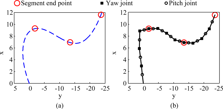
Results of 2-dimensional curve: (a) given desired curve, and (b) resulting robot configuration

The second curvature is given in 3-dimensional space as can be noted from Eq. (11). The results are illustrated in Figure 5.

Results of 3-dimensional curve: (a) given desired curve, and (b) resulting robot configuration
The given desired curve is shown in Figure 4 (a) and 5 (a), and the resulting robot configurations are shown in Figure 4 (b) and 5 (b). As can be seen from the results, the control scheme was able to pick up most of the geometric features of the given curve. It should be noted that the result is limited by the dexterity of the robot. Although the configuration used in this study is widely used for hyper-redundant robots, it does not offer high dexterity compared to other configurations, such as robots with universal joints. Thus, although the resulting configuration resembles the given curve, it may show a “zigzag” pattern due to the joint configuration of the robot. This pattern was also reported in other studies, such as [14]. Reducing the link length, l, or increasing the dexterity of the robot would further improve the outcome of the control scheme.
The proposed control scheme treats each module as an independent redundant robot and, thus, many issues in controlling robots can be resolved using the solutions proposed for redundant robots. For example, joint limits and kinematic singularities often limit the operation of a robot. However, using the proposed control scheme, the operator may impose additional Jacobian-based redundancy resolutions on the robot to effectively avoid joint limits and singularities at the cost of a heavier computational load, as the use of multiple redundancy resolutions may require an increase in the number of redundant joints.
The fitting algorithm can be regarded as the iterative computation of the end position of a link. Given the DH notation of a module, the end position of link i can be easily found using the forward kinematics computation as shown in Eq. (12):
where
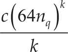
Normally, c is the total number of DOF of a hyper-redundant robot. However, using the proposed modular control scheme, c can be reduced to the 1/m of the value without the modular scheme, thus reducing the computational load to 1/m. The reduction may seem less apparent in a hyper-redundant robot with a small number of DOF. However, the proposed scheme would be particularly helpful for a hyper-redundant robot with a large number of DOF, for which a single controller cannot handle the fitting algorithm in real-time. Note that this analysis focused on the computation of the end position of links as it requires the heaviest computation. Other necessary computations, such as the Jacobian, can be easily computed without much computational burden.
In this study, we proposed a novel modular control scheme for hyper-redundant robots. Through the use of modularization, redundancy resolution and a fitting algorithm, the control of a hyper-redundant robot in three-dimensional space was achieved. The performance of the scheme is verified through simulations. From this study, the following conclusions were drawn:
The proposed scheme reduces the computational load of hyper-redundant robots by enabling parallel computation. The robot is divided into modules, and each module can be fitted separately. The proposed scheme is applicable to any hyper-redundant robot. The algorithm is not restricted to a joint configuration and is applicable for the curve given in both two- and three-dimensional spaces. A weight least-norm solution that preserves the configuration of the robot is proposed. This can be used to enable parallel computation. Furthermore, it can be used to control the end-effector position of a hyper-redundant robot to perform various tasks.
Footnotes
5.
The authors disclosed receipt of the following financial support for the research, authorship and/or publication of this article: This study was supported by grants from the National Research Foundation of Korea (NRF-2014024875) and the National Cancer Center of Korea (NCC-1210170).