
Abstract
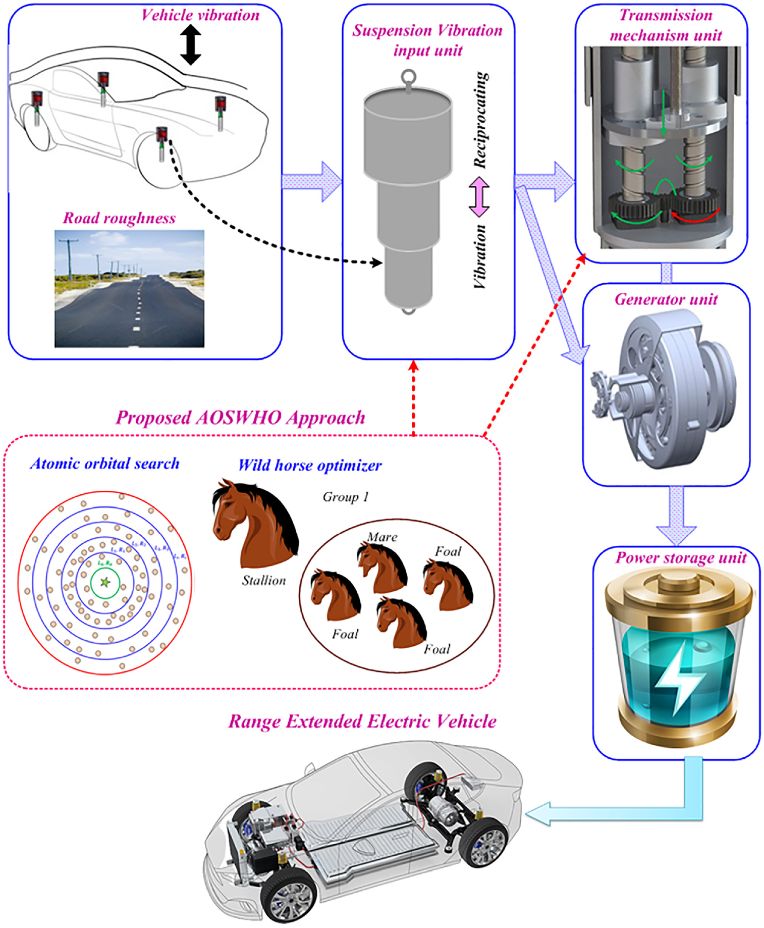
This article proposes a hybrid system for increasing the electric vehicles’ (EVs) driving range considering regenerative shock absorbers. The proposed hybrid approach is a combination of atomic orbital search (AOS) and wild horse optimizer (WHO); later, it was called AOSWHO method. The major objectives of the proposed work are to extend vehicle range, reduce the charging time of the vehicle, reduce the battery size, and increase the efficiency of vehicle. In this proposed work, linear Permanent magnet (PM) generators are used as the sole instrument and on-board source is utilized to absorb vibration energy of the moving vehicle. Here, the proposed method has four key modules: (a) suspension vibration input, (b) transmission mechanism, (c) generator module, and (d) power storage. A suspension vibration is mostly pretentious by road roughness and speed vibration, which is optimally handled by the proposed hybrid technique. The conversion of the alternating linear vibration into unidirectional rotation of generator shaft is processed by proposed hybrid technique. Based on the volume and efficiency of the dampers, a small volume, brushless DC motor with low rotor inertia is selected to produce electricity. By then, the proposed AOSWHO run on MATLAB site and its performance is related to several existing systems. From the simulation result, it is concluded that proposed system delivers an State of Charge (SOC) of 40.33, which is high compared to existing approaches.
Keywords
Introduction
In recent years, improving the energy performance of transportation vehicles has garnered great interest worldwide due to the necessity to diminish fossil fuel consumption. 1 Electric vehicles (EVs) are one of the clean and effective solutions to the fossil fuel crisis as well as excess carbon dioxide (CO2) emissions. 2 Many countries have urged policymakers and automobile productions to look for alternative fuels and enhance the energy efficiency of transport by the development of EVs. 3 However, the main drawback of the battery EVs are extremely limited mile range.4–8 Because of the limitations such as materials, capacity, reliability and standard battery system characteristics, this drawback is called “range anxiety.” 9 To overcome the drawbacks, researchers have majorly focused on the battery management approaches, 10 fast charging, and the selection of charging station site. 11
In the applications of extended range EVs, the above approaches are referred to as energy conservation methods. 12 More research into energy harvesting with alternative energy sources could result in an optimum and a new complete solution. 13 Regenerative shock absorbers are one of the most promising technologies for minimizing fuel consumption in road transport vehicles. 14 Shock absorbers, one of the important vehicle suspensions, are connected to the suspension spring and reduce the vehicle vibration while driving on rough roads. 15 When travelling on roads, the road surface roughness causes the vehicle to vibrate.16,17 Conversely, direct conversion of kinetic energy into electric energy is performed through regenerative shock absorber, and that energy is stored in the batteries or supercapacitors (SCs) for upcoming usage. 18
For the commercial vehicle, it is probable that a hydraulic regenerative shock absorber of 45–420 W may be created via standard driving and vehicle rolling mode. 19 Various energies are harvested under high vehicle speed and rough terrain. 20 The electromagnetic generator is highly skilled the model vibration frequency of vehicle, which converts kinetic energy into electric energy. 21 There are two categories of regenerative shock absorbers such as direct-drive and indirect-drive regenerative shock absorbers (RSAs). 22 If the vehicle is driven on a rough road, the displacement trigger caused by unevenness or bumps of the road leads to relative motion amid sprung and unsprung mass.23,24
Objectives and contribution
A hybrid method is proposed for increasing the driving range of EVs considering regenerative shock absorbers. The hybrid system is a combination of atomic orbital search (AOS) and wild horse optimizer (WHO); later, it was called AOSWHO method. Using the MATLAB/Simulink working platform, the proposed system is evaluated by comparing existing systems.
The novelty of the AOS method updating behavior is improved by the WHO method; hence, it is known as AOSWHO method.
The proposed system is incorporated with four units, namely, suspension vibration input unit, transmission mechanism unit, generator unit, and power storage unit.
Here, the proposed system has four key sections: (a) suspension vibration input, (b) transmission mechanism, (c) generator, and (d) power storage.
The remaining article is structured as follows: “Recent research works” section depicts recent research work and its background. “Configuration of regenerative shock absorber in view of twin ball screws transmissions with proposed approach” section clarifies configuration of regenerative shock absorber with proposed system. “Modeling of regenerative shock absorber parts” section described modeling of regenerative shock absorber parts. “Proposed AOSWHO approach-based management of regenerative shock absorber” section delineates proposed approach-based management of regenerative shock absorber. “Results and discussion” section defines simulation results and discussion. “Conclusion” section concludes the article.
Recent research works
Numerous previous research works used various approaches and features for onboard regenerative energy storage on EVs. Here, a part of them are revised.
Li et al. 25 introduced a novel energy regenerative shock absorber for imprisoning waste kinetic energy of the vehicle suspension system as well as generating electrical power. The introduced shock absorber was integrated with the vibration energy capturing unit, the motion conversion unit, the generator unit, and the electrical energy storage unit. The rough roads and speed variation caused the random vibration of the suspension which operated like a vibration energy capture unit. Electricity was generated by the generator unit and the accumulation of electricity in the SC was done by the electric energy storage unit. By using the various damping coefficients, the full benefit of the introduced absorber was obtained. Wang et al. 26 introduced regenerative shock absorber transmission for increasing EV uses. The major purpose of the presented absorber is to increase the EV range. The presented unit was incorporated into suspension vibration input unit, transmitting unit, generator unit, and power storage unit. The road roughness and irregular linear oscillations were given to the suspension vibration input unit.
Yu et al. 27 introduced a dual-electric-port drive for flux-modulated switch reluctance machine (SRM) using charging capacity for EV application. Among dual port as well as count of power switches were diminished by control of zero-sequence current excitation. Performance of the machine was improved by carrier-based Pulse-width modulation (PWM) and harmonic current suppression approach. The DC and AC charging were employed by the current distribution control approach along with the power factor correction approach. Nguyen et al. 28 introduced a shifting approach, two-motor drive powertrain energy management for increasing the range of electric buses. There were three models such as multi-body dynamic model, shift schedule, and optimal shifting approaches that were incorporated in the introduced system. The transient investigation was performed, first, by using the dynamic model. Second, through the integration of priority factor fetching gear into the equivalent motor was performed by shift schedule. The single- and double-gear changes were analyzed based on the vehicle speed as well as power under shift agenda. Elimination of torque interference under possible gear changes was performed by optimal shifting approach. The energy management of the system was performed by the model predictive control which reduces the consumption of fuel and optimizes the torque allocation to two motors.
Mongkoldee et al. 29 presented the particle swarm optimization (PSO) approach for energy storing determination in the FC hybrid intercity bus. The introduced system’s major energy buffer was the batteries or SCs. The driving cycle was modified by the introduced system. The key purpose of the presented system was decreasing the cost of energy storage and FC as well as minimizing the hydrogen consumption of the total route. Wu et al. 30 suggested the convex optimization and data fitting reduce the cost of energy consumption for the entire urban railway line. The introduced system was considered in two steps to improve train operation, time schedule, and energy management. The data fitting depending on previous research results was utilized to minimize the energy consumption and convex optimization was utilized. Wu et al. 31 introduced the optimal driving method of electric trains for minimizing energy consumption. The introduced system considered the three energy storage devices such as SC, flywheels, and Li-ion battery. The dynamic discharge/charge characteristic of OESD on railway operation was improved considering the OESD investment cost and dynamic energy range of dissimilar OESD sorts. The eco-driving approach and the OESD discharge/charge behavior were different within various types of OESDs.
Allotta et al. 32 performed innovative damping technologies to improve railway vehicle performance based on dynamic stability and comfort. Pulcinelli et al. 33 performed an innovative controlled hydraulic pump solution that greatly recovers efficiency and decreases overall loads, preserving very high performance based on dynamic behavior and relative frequency response.
Background of research work
A review of current research work displays that regenerative shock absorber and energy saving in EV are the most contributing factors. In general, the automobiles were wasting energy stored as heat in fuel. This includes various losses in various areas like engine vibration, losses during braking, and traction losses. Therefore, only 26% of fuel available to the vehicle was used to overwhelm the road friction resistance. Dispersion of vibrational energy by shock absorbers on vehicle suspension in influence of road irregularity as well as vehicle acceleration or deceleration was a significant loss. Hence, the regenerative shock absorbers were introduced to overcome the issues. Moreover, it recovers and stores energy by utilizing transmission mechanism unit, generator, and battery. Compared to conventional shock absorbers, regenerative shock absorbers may recover a high vibrational energy rate, but it has many drawbacks. Regeneration shock absorbers may complement by targeting the next main issues. Regenerative shock absorbers were commonly less efficient and do not function as conservative shock absorbers; the utilization of recovered energy should be fully considered. Although the current approaches cover to some extent the energy storage issues in the shock absorbers, several aspects of regenerative shock absorbers were not yet clear. Efficiency and structural simplicity were at odds when considering huge performance and reliable simplicity of the system. In the existing research, the regenerative shock absorber increases efficiency and the EV range. The comparatively higher impact force caused by the oscillating motion was still in that system and was not able to achieve the appropriate damping ratio amid the upward and downward progression, to deliver an easy riding capability for the passengers. These drawbacks inspired us to do the research work.
Configuration of regenerative shock absorber in view of twin ball screws transmissions with proposed approach
Figure 1 shows regenerative shock absorber in view of double ball screw transmission with the proposed method.
Configuration of regenerative shock absorber in view of twin ball screws transmissions.
The input of the shock absorber is reciprocating linear vibrations emitted from the cylinder and the vibration is occurring due to the passing of vehicle on uneven roads or changing speed. The outcome of the shock absorber is nuts moving down or up by the rods. The suspension vibration input unit is described as the association of cylinders, rods, and nuts. The storage unit is considered as the fuel cell (FC) and battery, which are utilized in the power storage unit. Battery charging is done through the storage unit. The proposed AOSWHO method is employed to handle the vibration unit and the generator unit.
Structure of the suspension vibration input unit
Figure 2 displays the structure of the regenerative absorber and its parts. Suspension vibration input unit is connected to the upper and middle lower cylinder. The proposed absorber is used to minimize vibration and enhance ride comfort. The energy is stored and recovered by using the transmission mechanism unit, generator, battery, and FC. Figure 3 displays regenerative shock absorber installation. The frame and body vibrations are affected by damping force34,35 of internal engine assembly and generator.
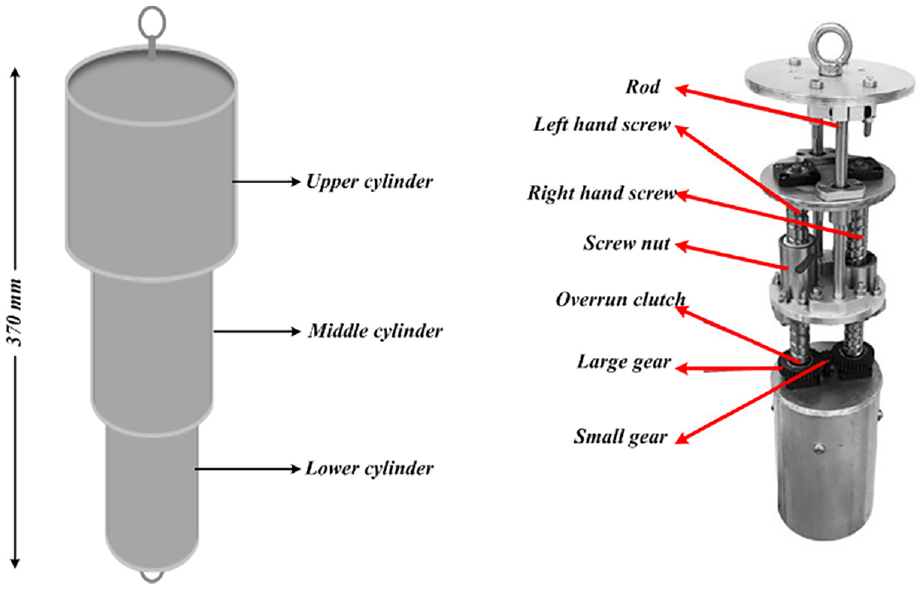
Structure of the suspension vibration input unit.
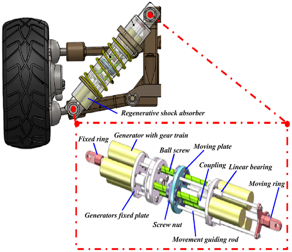
Installation of energy regenerative shock absorber.
The suspension vibrations are mostly influenced by the roughness of the road. Regenerative shock absorber extends and contracts by the reaction force’s torque. Hence, it reveals that the road roughness and speed variation majorly affect the suspension vibration input.
Transmission mechanism unit
It acts as a link between the suspension vibration input unit and the generator unit. The main core of the regenerative shock absorber is the transmission mechanism unit. The upper and middle cylinders receive reciprocal oscillations induced in the vibration input unit. In cylinders, the alteration of reciprocal linear vibration to the unidirectional generator shaft rotation 36 is performed by the transmission mechanism unit. In this article, there are two screw nuts that are collected by two ball screws and the shaft terminal is connected to the inner cylinder. At ball screw, the balls travel through the nut, screw, and splines. The balls that are sent to the nut’s ball return system move in a straight line from the start point to the end point and back again.
Transmission mechanism unit movement is displayed in Figure 4. At the top and middle ends of the cylinder, two ball screws are inserted. The overrun clutches are connected by ball screws on the inside and large gear on the outside. If the inner and outer cylinders receive the reciprocating vibration, then the screw nuts will move up and downward simultaneously. One of the clutches is disconnected while the other is engaged in large gear. Hence, the unidirectional rotation is continuously occurring in the small gear. Screw leads are designed to obtain the suitable damping and increase the mechanical efficiency. If the input speed and generator parameters are constant, then the ball screws will lead to several rotational generator speeds.
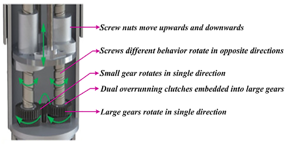
Transmission mechanism unit movement. 26
Generator unit
Generator is a power generation unit, which is placed inside of the lower cylinder via circular plate. 37 To generate electricity, this article utilized a DC brushless motor with low rotor inertia based on shock absorber volume and efficiency. The generator rotational speed is constantly varying, depending on irregularity of the different excitation conditions and the clutch clearance that arises while varying direction. Hence, the generator output becomes unstable and irregular.
Power storage unit
Power storage system is essential to store energy and charge, and the current rectifier with voltage regulator is utilized to attain steady state current. The AC current is converted into DC current using the rectifier.26,38 The power load stabilization and the generator output voltage adjustment are obtained by controlling the generator excitation current through the voltage regulator. EV battery is charged by the battery and FC. Figure 5 portrays the circuit diagram of the rectifier.
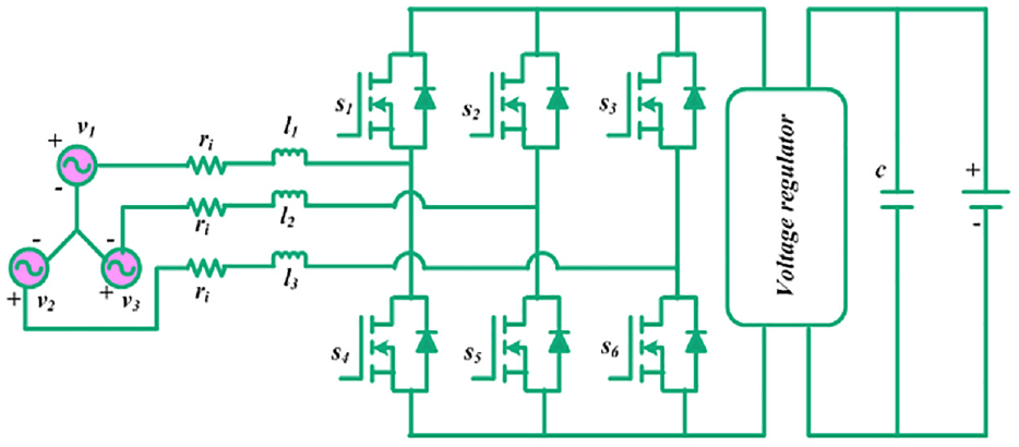
Circuit diagram of rectifier. 26
Battery model
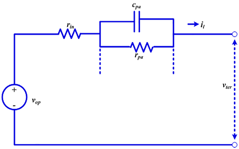
The primary energy storage system (ESS) is a battery connected to the DC bus. The parameters like temperature and SOC of the battery are utilized to charge and discharge the battery. The graphic diagram of the battery is portrayed in Figure 6.
Graphic diagram of battery.
The simple equivalent circuit that depends on resistance and capacitance is shown in Figure 6, which is incorporated with open-circuit voltage and the interior resistance of the battery. The battery characteristics are defined by Maravandi and Moallem 34 as follows
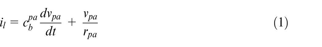

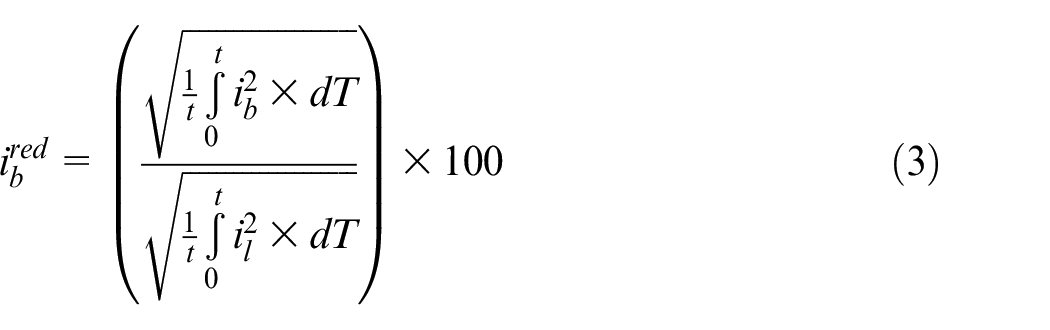
The ratio of battery current reduction is defined as
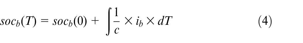
The primary SOC is necessary to control SOC variation and the charge change. The SOC of the battery is defined as
For simplicity, resistive heat is defined as
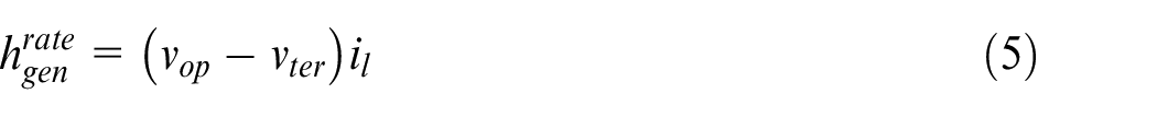
where
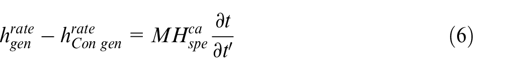
where M refers to mass,
FC model
FC is incorporated with the FC stack and hydrogen high pressure tanks which give the fuels. The output features of FC are controlled by a voltage regulator. The voltage of the FC is described by
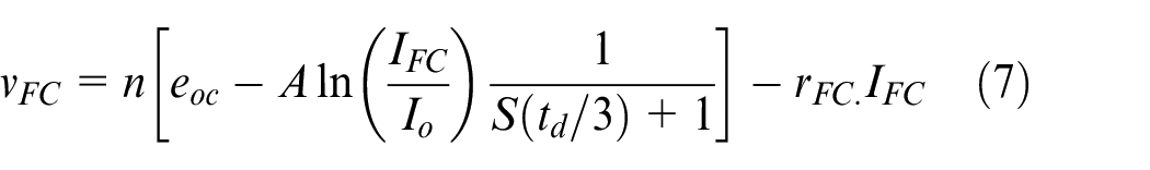
where number of cells on series is
Modeling of regenerative shock absorber parts
Various parts like generator, straight gears, and ball screws are incorporated into regenerative shock absorbers. The modeling of these parts is described below.
Ball screw fatigue life analysis
The equivalent rotation speed is calculated by
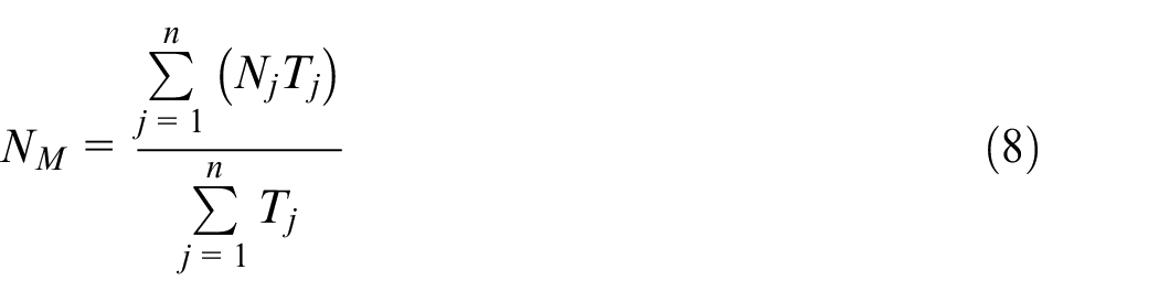
where reciprocating cycle is represented as j, rotation speed as
Assume that under equivalent load, equal speed, and maximal axial dynamic load condition, the ball screw is operated. The rated fatigue life24,39 is described as
where expected life is denoted as
Rotary damping analysis of the generator
In ball screw mechanism, a generator with conventional gear mechanism and charge circuit is used to obtain regenerative damping capability.34,40 If the vibration is given by the suspension, then the rotation of generator shaft happens by the transmission mechanism unit. 26 As a result, three-phase AC generated with brushless DC generator, charging unit that energy is stored in the fuel and battery, provides concurrent rotary damping to shock absorber.Figure 7 portrays the circuit diagram of the three-phase generator
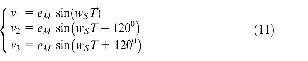
where induced voltage of each phase is denoted as
where power loss is denoted as
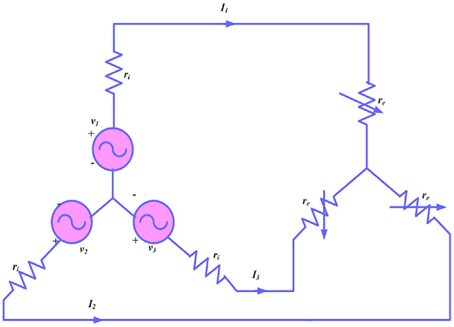
Circuit diagram of three-phase generator. 26
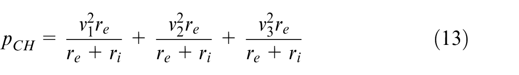
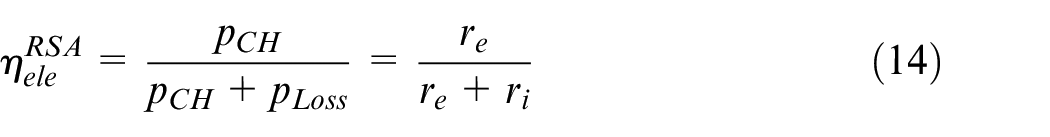
The regenerative shock absorber efficiency is described as
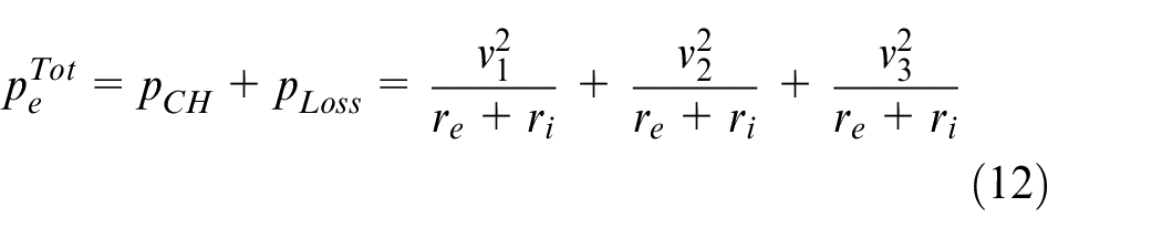
Then, the total power is described by

where generator shaft rotary speed is denoted as
Based on the power balance, the total power is described by
Based on the torque, power is described by

where electromagnetic torque is denoted as

where rotary damping coefficient is denoted as

The generator rotary damping coefficient using charge circuit is described by
Regenerative shock absorber linear damping coefficient analysis
A shock absorber input power is described by
where power loss produced through friction
41
at ball screw, straight gear, and generator is denoted as

where ball screw efficiency is denoted as
where excitation shock absorber speed is denoted as
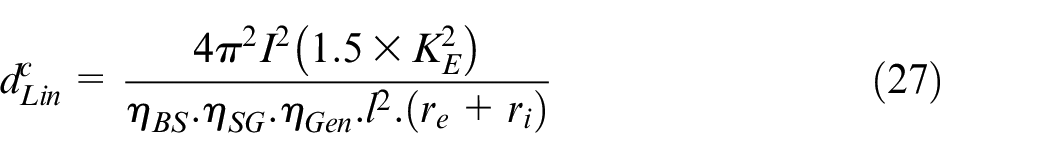
Applying (22) and (18) into (21)

By applying the rotational rotary speed of ball screw, then linear damping coefficient is described by
The total shock absorber efficiency is described by

where mechanical efficiency is
Proposed AOSWHO approach-based management of regenerative shock absorber
This article proposes an AOSWHO approach to extend the EV range, in which regenerative shock absorber is considered here. Figure 8 displays the control structure of the proposed system. There are four units utilized to carry out the operation of the absorber. First, the vibration based on road roughness or speed change is absorbed by the on-board source 42 and it is given to the suspension vibration input unit to process further units like transmission mechanism unit, generator unit, and the power storage unit. The battery and FC are used to store the power of the system and extend the life of the battery. A brief description of the proposed system is provided below.
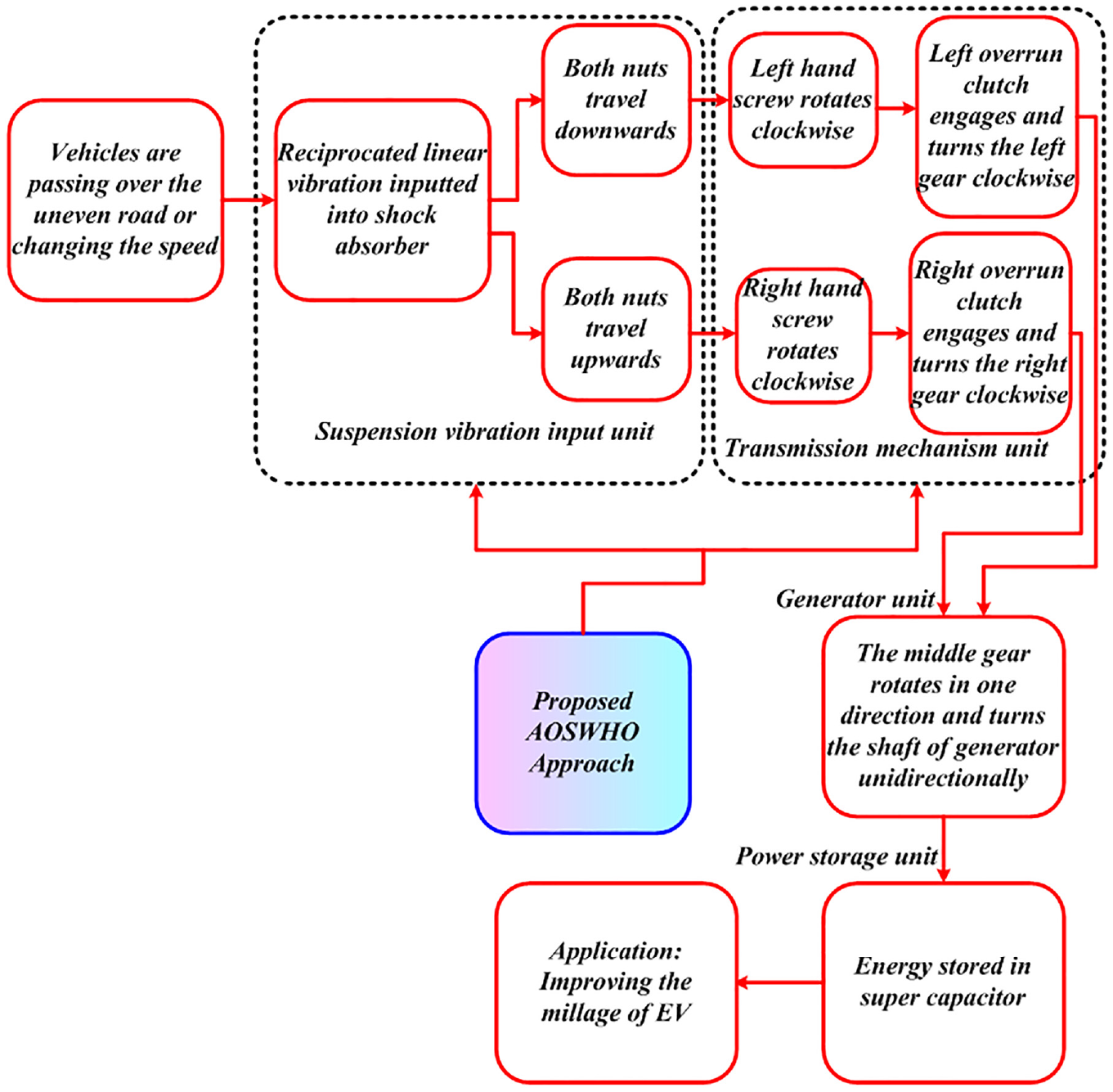
Control structure of proposed system with proposed approach.
Proposed AOSWHO approach
AOS is a meta-heuristic optimization method inspired by quantum mechanics principles of electron activity around the atom nucleus. The flow of electrons in waves is added to an unknown destination as an alternative to orbit in the established routes around the nucleus. 43 The orbitals are determined by the likelihood of electron placement. A mathematical approach is used to decide the likelihood of a given location of any electron around the atom nucleus. Electrons change positions instantly as time passes, forming a cloud of charge. WHO 44 is a meta-heuristic method stimulated through environmental behavior of wild horses. This article suggests a hybrid AOSWHO method for controlling the input and transmitting unit of absorber. The updating behavior of the AOS is improved through the WHO system. The step-by-step process of the AOSWHO approach is defined as follows.
Step 1: initialization
Initialize input parameter is defined as
Step 2: random generation
After the process of initialization, the input parameters are randomly formed
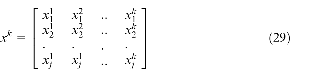
where k denotes dimension.
Step 3: fitness function
Fitness is determined by objective function. It is defined as

where
Step 4: compute binding state and energy
It is computed with the following equation
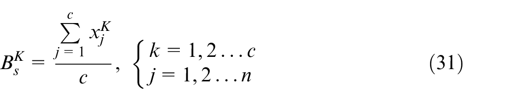
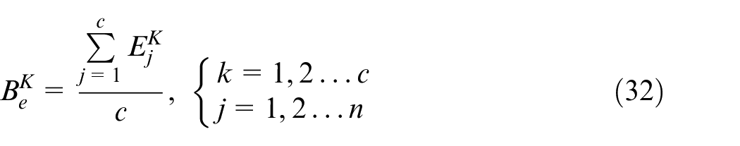
where c denotes candidates count in kth layer.
Step 5: update random parameters
Random parameters such as
Step 6: compute photon rate
Photon rate is used to compare the different interactions based on electron absorption and emission
where
Step 7: compare energy level to binding energy
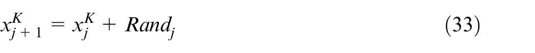
If the energy level is greater to binding, the location is updated
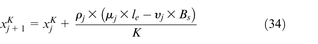
If the energy level is less than binding, the location is updated

Determine the binding state and energy using the preceding two equations.
Step 8: update the parameter using WHO approach
The WHO technique is used to update the parameters based on the comparative results.
Step 9: find best global solution
Binding state and energy determine the optimum global solution.
Step 10: termination criteria
Stop the process if the ending criteria are met; otherwise, proceed to step 3. Figure 9 depicts a flowchart of the proposed AOSWHO process.
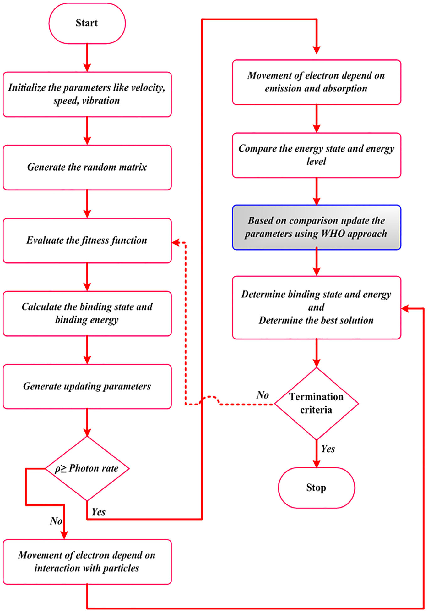
Flowchart of the AOSWHO approach.
Results and discussion
This article describes the performance of the AOSWHO method depending on simulation. Here, a regenerative shock absorber and battery and FC are used to increase the EVs range. The proposed AOSWHO approach can optimally handle the suspension vibration input. Moreover, the alteration of reciprocating linear vibration to unidirectional rotation of the generator shaft is also processed by the proposed hybrid approach. The AOSWHO is performed on MATLAB site related to several existing schemes like WHO and AOS.
Case 1: performance of proposed based on decreased input
The performance of the proposed method is investigated depending on input reduction. Analysis of the reference acceleration is portrayed in Figure 10. The acceleration of the vehicle is 0.7 m/s2 at 0–4 s, and then it is reduced to 0.55 m/s2 at 4 s. At 4–8 s, the acceleration of the proposed approach is 0.55 m/s2. Analysis of the speed of the car is portrayed in Figure 11. Speed is increased 0–75 m/s at 0–8 s. Figure 12 shows the analysis of the motor parameters using the proposed technique. Speed of the motor is shown in subplot 12(a). Torque of the motor is shown in subplot 12(b). Motor power is shown in subplot 12(c).
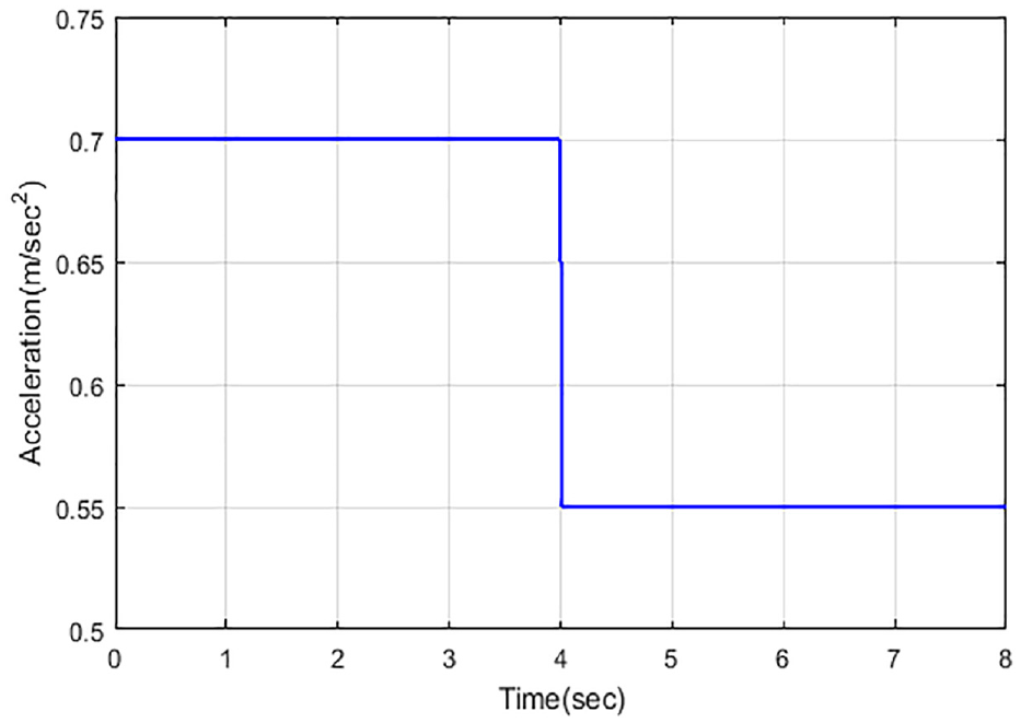
Analysis of reference acceleration in case 1.
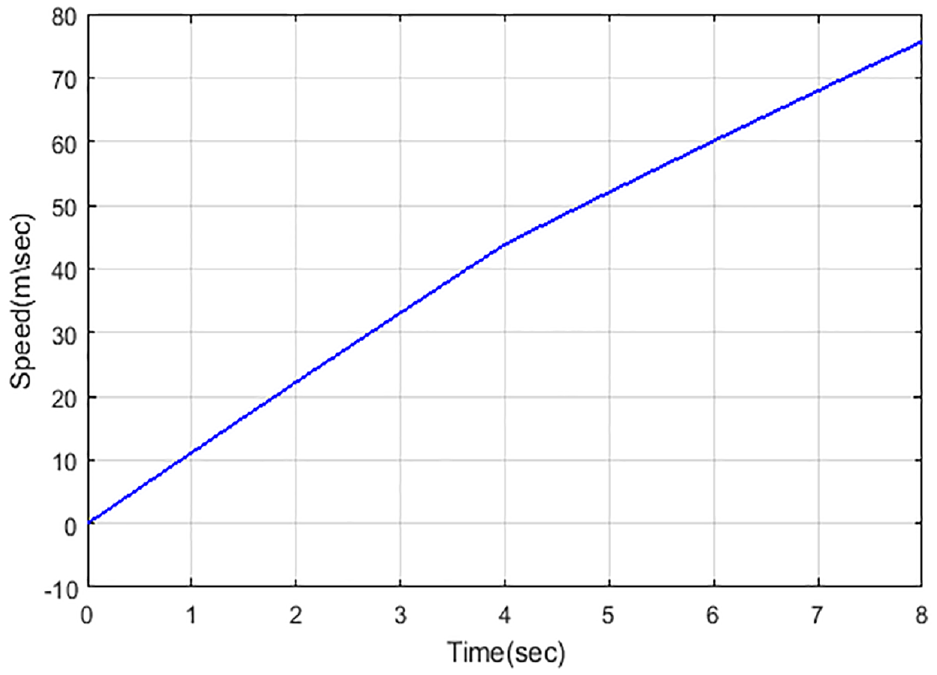
Analysis of speed of the car in case 1.
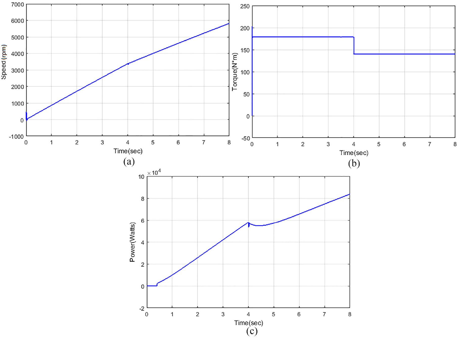
Analysis of the motor: (a) speed, (b) torque, and (c) power in case 1.
Analysis of FC voltage current and power is displayed in Figure 13. Subplot 13(a) displays the FC voltage. The voltage of the FC is increased from 0 to 170 V at 0.5–4 s, and then it is somewhat reduced and enlarged to reach 270 V at 4–8 s. Subplot 13(a) displays the FC current. The current of the FC is decreased from 420 to 335 A at 0–4 s; again, it reduced to 310 A at 4–8 s. Subplot 13(c) displays the FC power. The power of the FC is increased from 0 to 5.9
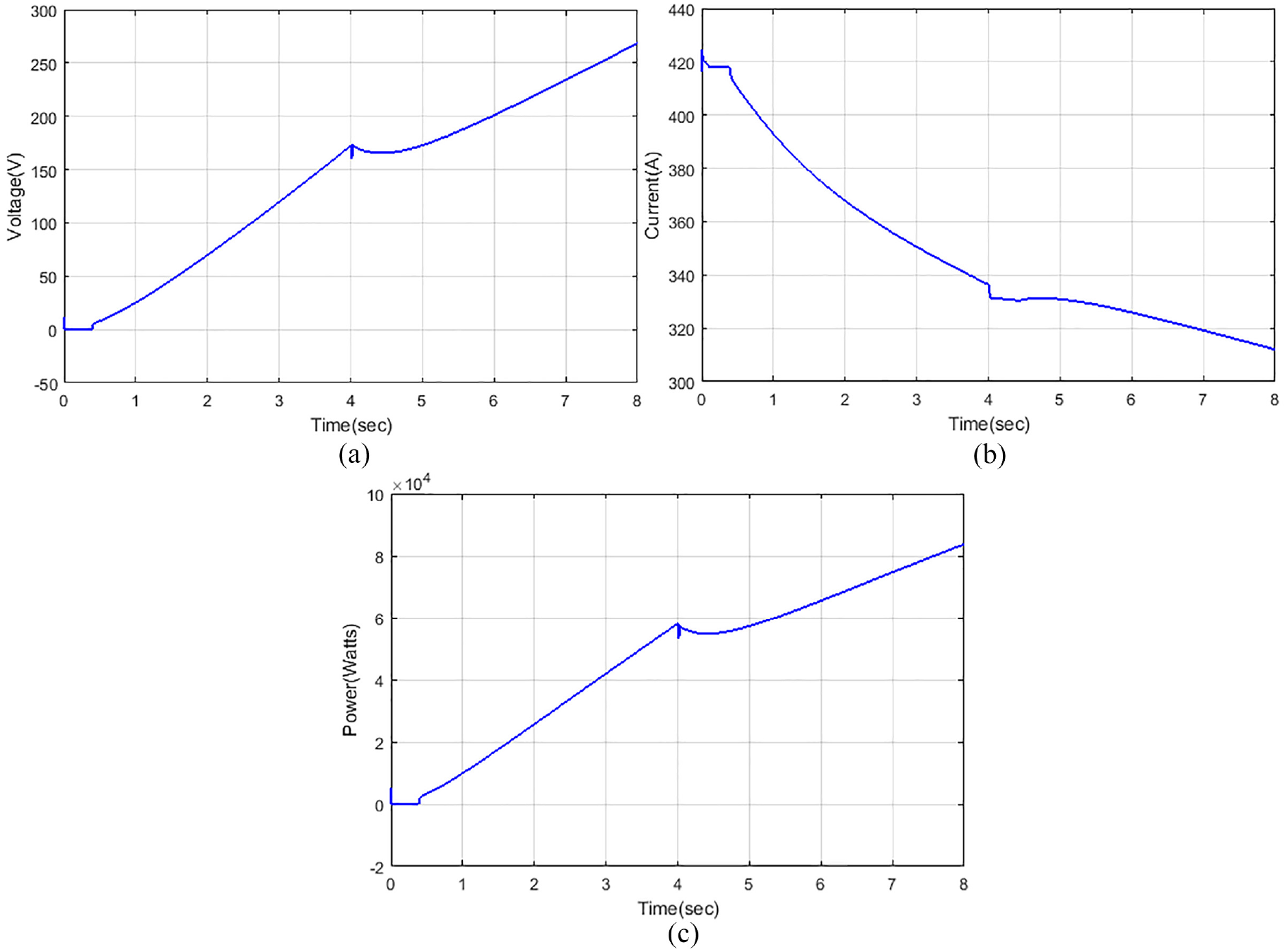
Analysis of the fuel cell: (a) voltage, (b) current, and (c) power in case 1.
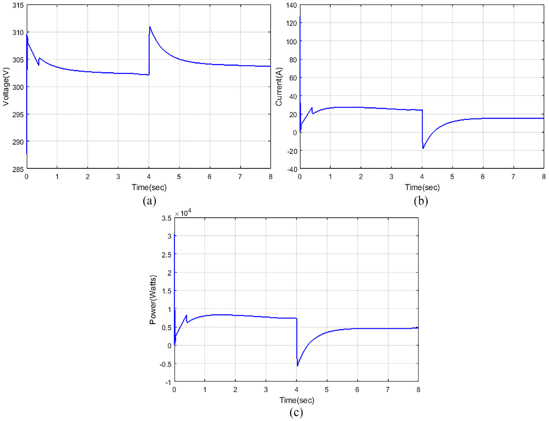
Analysis of the battery: (a) voltage, (b) current, and (c) power in case 1.
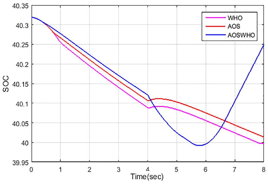
Comparison of SOC of proposed and existing method in case 1.
Case 2: performance of proposed method based on increased input
The performance of the proposed scheme which is investigated depends on increased input. Analysis of the reference acceleration is portrayed in Figure 16. The acceleration of the vehicle is 0.7 m/s2 at 0–4 s, and then it increased to 0.85 m/s2 at 4 s. At 4–8 s, the acceleration of the proposed approach is 0.85 m/s2. Analysis of the speed of the car is portrayed in Figure 17. The speed increased from 0 to 75 m/s at 0–8 s. Analysis of the motor speed, torque, and power is portrayed in Figure 18. The speed of the motor is shown in subplot 18(a). Speed is increased from 0 to 5900 r/min at 0–8 s. Torque of the motor is shown in subplot 18(b). The torque is increased from 1 to 200 Nm at 0 s, and then it decreased with 180 Nm at 0.1 s. It is stable to 180 Nm at 0–4 s and then it increased to 220 Nm at 4–4.6 s. Then, it reduced to 80 Nm at 6.6 s and again it slightly decreased to 75 Nm at 6.6–8 s. Power of the motor is shown in subplot 18(c).
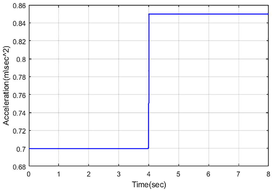
Analysis of the reference acceleration in case 2.
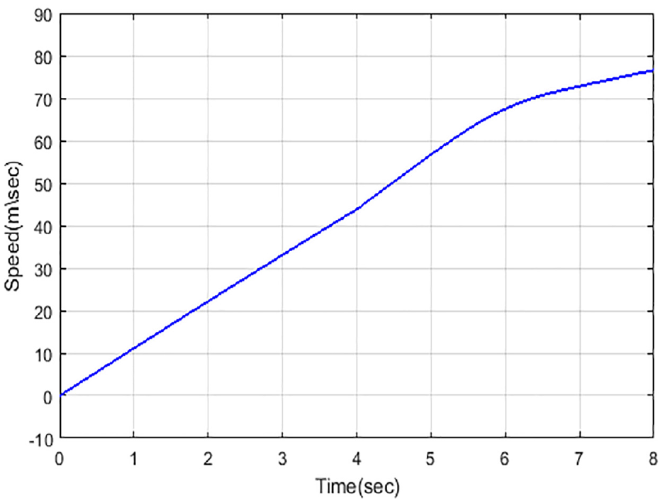
Analysis of speed in case 2.
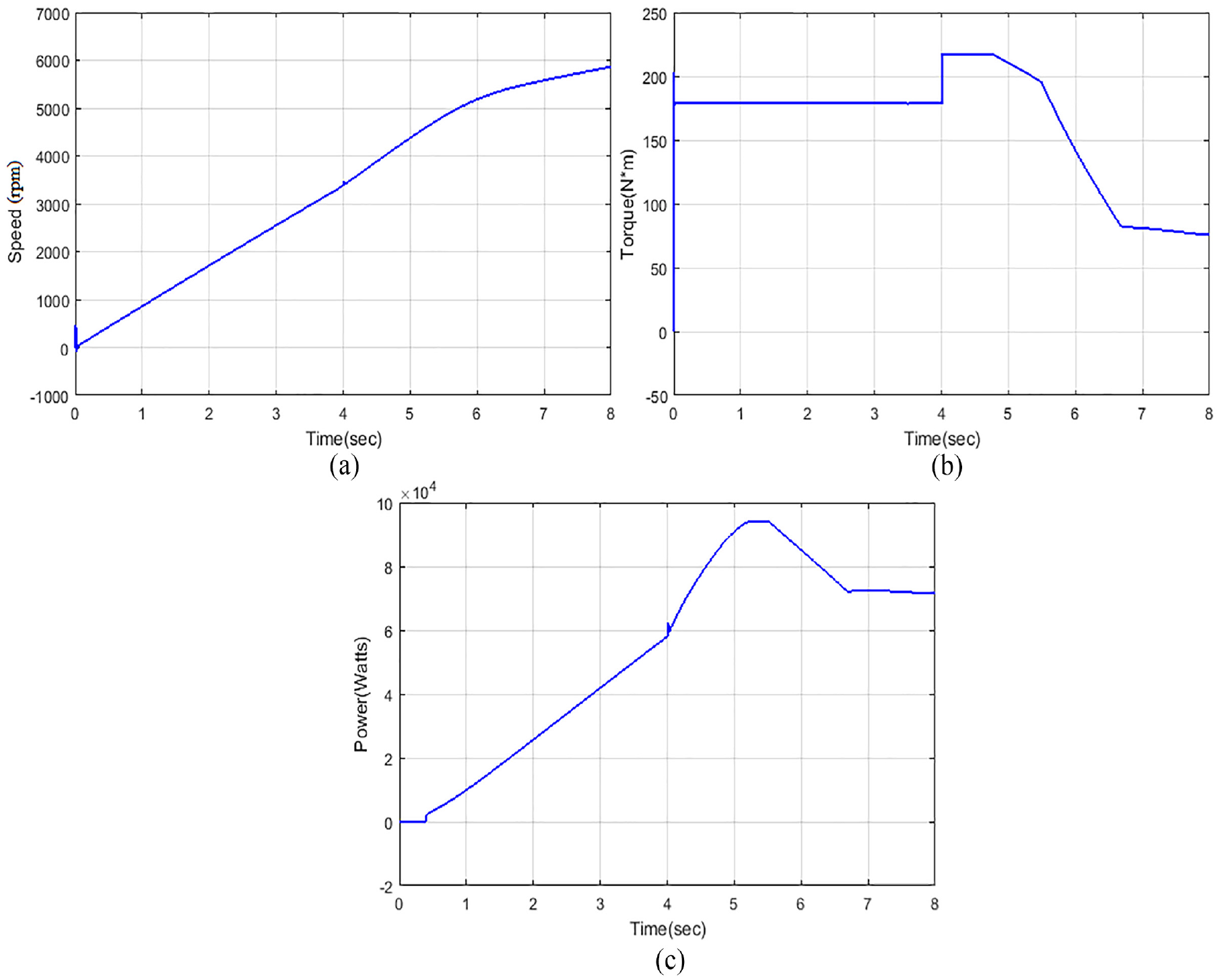
Analysis of the motor: (a) speed, (b) torque, and (c) power in case 2.
Analysis of the FC voltage current and power is displayed in Figure 19. Subplot 19(a) portrays FC voltage. Subplot 19(a) displays the FC current. Subplot 19(c) displays the FC power. From this simulation, it is accomplished that proposed system power is increased at increased input. The performance of battery voltage, current, and power is portrayed in Figure 20. Subplot 20(a) displays the battery voltage. From this comparison, it is concluded that if the input is increased, then the voltage also increases. Subplot 20(b) displays the battery current. Subplot 20(c) displays the battery power. Comparison of SOC of proposed and existing system is displayed in Figure 21. SOC of battery at the start is 40.33 for the proposed approach and it decreased to 40.13. For analyzing at the point of 4 s, the proposed approach’s SOC is 40.13.
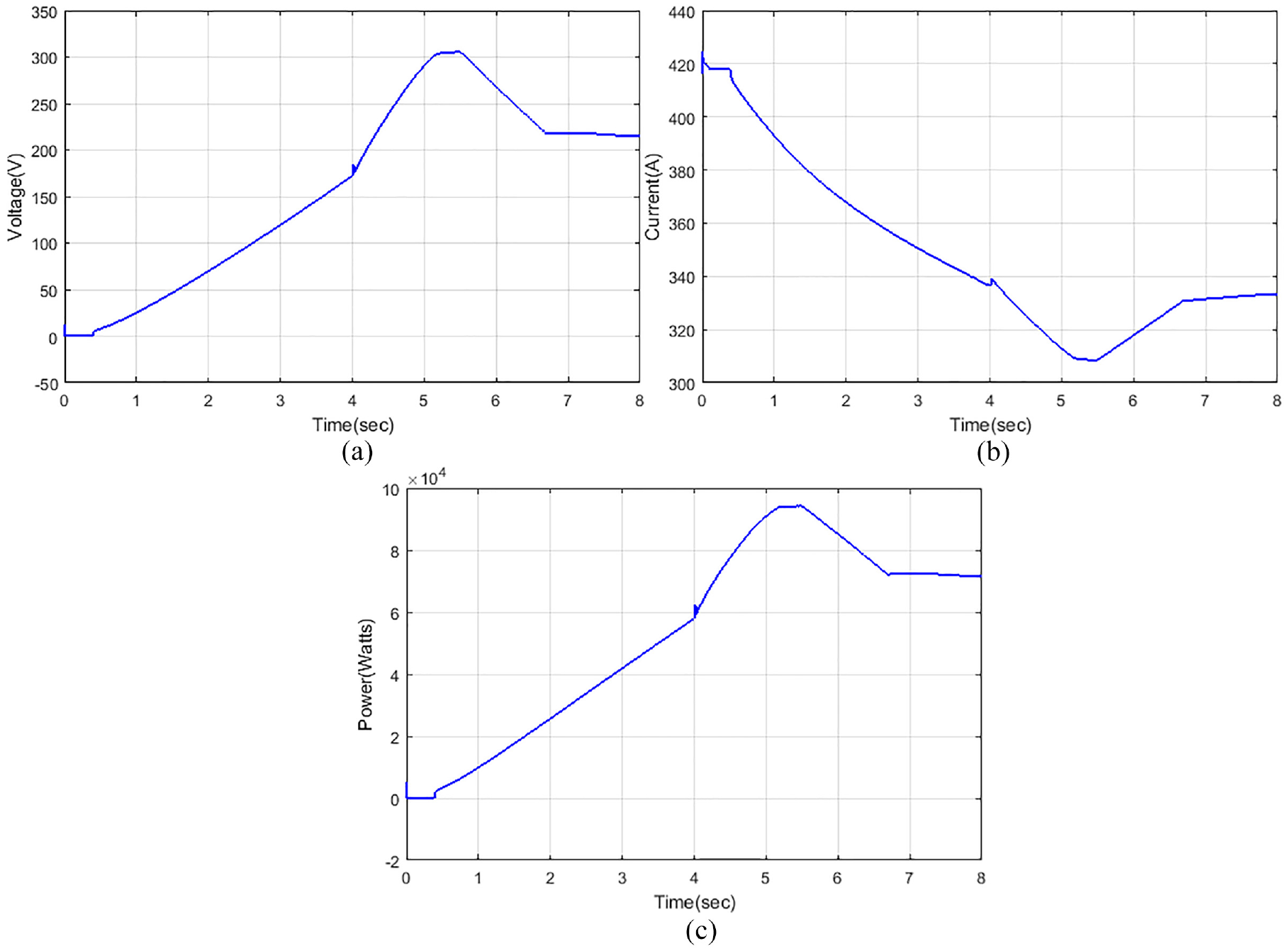
Analysis of the fuel cell: (a) voltage (b) current, and (c) power in case 2.
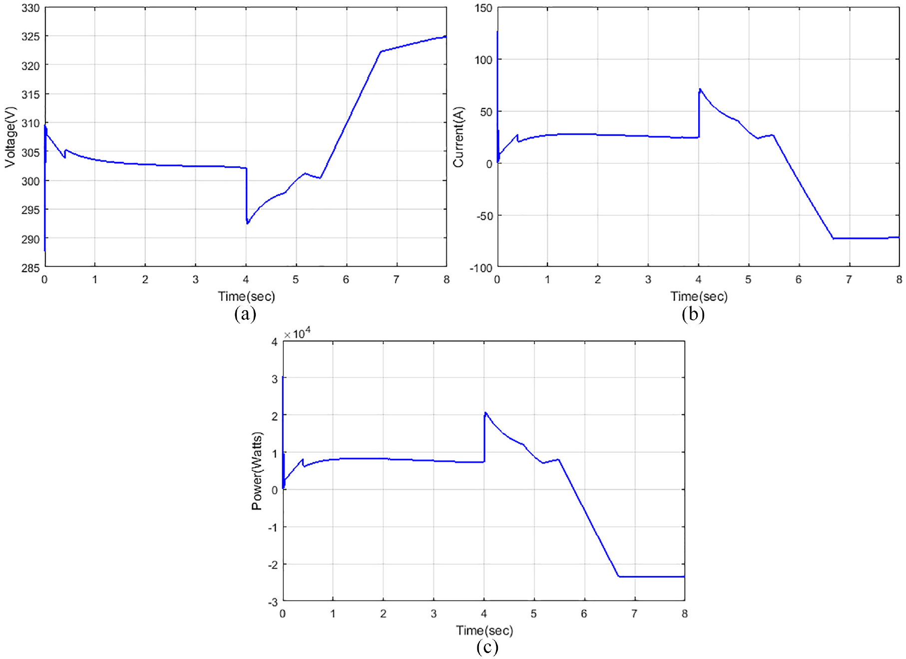
Analysis of the battery: (a) voltage, (b) current, and (c) power in case 2.
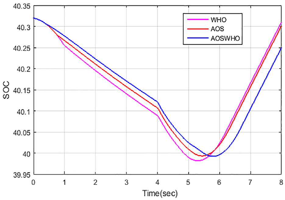
Comparison of SOC of proposed and existing method in case 2.
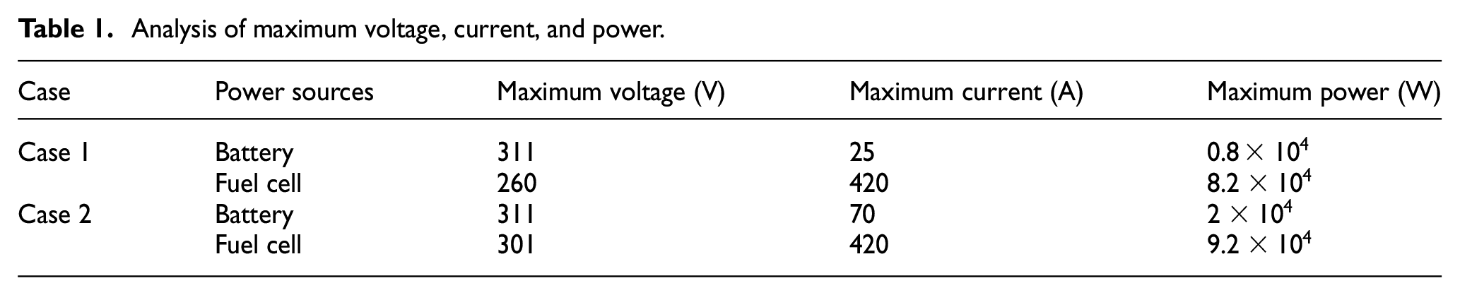
Analysis of maximum voltage, current, and power under cases is tabulated in Table 1. Under case 1, the maximum voltage for the battery is 311 V, the maximum current of 25 A, and then the resultant maximum power is 0.8
Analysis of maximum voltage, current, and power.
Statistical analysis of several methods is portrayed in Table 2. The mean, median, and standard deviation for vehicle handling comfort using WHO technique are 27.7%, 10%, 9%, and 45%. The mean, median, and standard deviation for stability using WHO system are 22.9%, 5%, 12%, and 30%. The mean, median, and standard deviation for vehicle handling comfort using AOS technique are 28.9%, 12%, 11%, and 48%. The mean, median, and standard deviation for stability using WHO system are 23.5%, 9.5%, 13.5%, and 38%. The mean, median, and standard deviation for vehicle handling comfort using proposed technique are 30.01%, 15%, 14%, and 58%. The mean, median, and standard deviation for stability using WHO system are 25%, 13%, 16%, and 60%.
Statistic analysis of several systems.
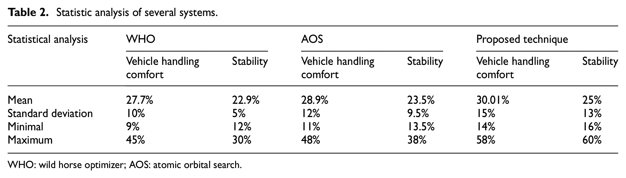
WHO: wild horse optimizer; AOS: atomic orbital search.
Efficiency comparison is tabulated in Table 3. The efficiency for the WHO, AOS, and the proposed technique is 82.13%, 77.26%, and 97.54%, respectively.
Efficiency comparison.
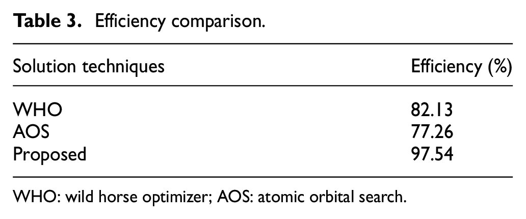
WHO: wild horse optimizer; AOS: atomic orbital search.
Conclusion
This article suggests an efficient hybrid AOSWHO method for increasing EVs’ driving range considering regenerative shock absorbers. The proposed approach is optimally handling the suspending vibration input unit, which is influenced by roughness of road and speed change. Moreover, the alteration of reciprocating linear vibration to unidirectional rotation of the generator shaft is also processed by the proposed hybrid method. The proposed AOSWHO is performed on MATLAB site and its competence is related to various existing approaches such as WHO and AOS. The performance of the AOSWHO is evaluated under two cases like input increase and input decrease. The brushless DC motor is utilized in the proposed approach and analyzes the speed and torque characteristic of the motor. The battery and FC voltage, current, and power of the AOSWHO approach are examined. From analysis, it is concluded that the AOSWHO approach provides high SOC and increases the range of the vehicle.
Footnotes
Data availability
Data sharing is not proper to this manuscript as no innovative data were formed or observed on this investigation.
Declaration of conflicting interests
The author(s) declared no potential conflicts of interest with respect to the research, authorship, and/or publication of this article.
Funding
The author(s) received no financial support for the research, authorship, and/or publication of this article.