
Abstract
The operating condition of ball screws is generally applied to ensure the ball screws with a high transmission efficiency and a high positioning accuracy. Aiming at the optimal operating condition of double-nut ball screws, a transmission efficiency model considering the kinematic analysis and lubrication status was proposed. Firstly, the distributions of the film bearing pressure, asperity bearing pressure, film thickness, and ratio of the asperity bearing pressure were determined based on the Reynolds equation. Subsequently, the transmission efficiency model was established by calculating the friction coefficient and friction torque of ball screws under various lubrication statuses and operating conditions. The optimal operating condition of double-nut ball screws can be determined by estimating the transmission efficiency and lubrication status to improve the manufacturing quality. Finally, a friction torque test based on the simulated model was designed and implemented on a self-designed bed for validation of the proposed model. The comparisons showed that the experimental friction torque was consistent with the simulated friction torque, which verified the effectiveness and correctness of the transmission efficiency model. Results showed that the optimal operating conditions of the entrainment velocity and axial working load could ensure high transmission efficiency and a good lubrication status, which are of great reference to the green processing and manufacturing fields.
Keywords
Introduction
The double-nut ball screws are widely used in the industrial field due to their excellent performance of high precision and high transmission efficiency.1–3 However, the transmission efficiency of ball screws is greatly influenced by the actual operating conditions and the lubrication status. Thus, it is necessary to investigate the transmission efficiency of ball screws regarding their properties such as kinematics, force balance, and elastohydrodynamic lubrication (EHL).
The EHL problem is widely studied under point contact4,5 and line contact.6,7 In order to investigate the lubrication performance of the working ball, a thermal EHL model the Reynolds equation (RE) of ball screws when the multidirectional load was used. Mu and Feng 8 solved the isothermal elliptical contact EHL program of ball screws and obtained oil film thickness and pressure. Their results showed that the film thickness becomes smaller with the increase of film contact pressure. Nogi et al. 9 presented a numerical analysis of EHL with grease in point contacts to predict the grease film thickness at low speeds, which can increase with decreasing the speed and exceed the base oil film thickness by orders of magnitude. Wang et al. 10 developed a newly transient mixed EHL model to study the transient friction, temperature and contact fatigue behaviors in different contact trajectories for spiral bevel gears. Pei et al. 11 analyzed the mixed EHL solution of line contact with a non-Gaussian rough surface, and determined the dimensionless film contact pressure and film thickness. Guiggiani 12 proposed a boundary element method to solve the lubrication problem of finite bearing, and this method allows the RE to be easily transformed into a constant coefficient equation, making the BEM application a straightforward task. However, the lubrication state of ball screws can also be indicated with the ratio of the asperity bearing pressure, which is not explored in the above research.
In order to investigate the transmission efficiency of the double-nut ball screws (DNBSs), the friction coefficient (FC) between the working ball and the screw/nut raceway should be determined.13,14 Chen et al. 15 determined the adhesion FC formula between wheel and rail under a water lubricated condition for a variety of values of surface roughness, rolling speeds, and contact load. Their results showed the adhesion FC is largely affected by the surface roughness. Zhao et al. 16 proposed a friction coefficient calculation method based on the bearing experience value and the structural characteristics of ball screws. Barbu et al. 17 determined the instantaneous friction coefficient of the ball screw from the relationship of dependency, idle friction torque, preload force, and screw speed. The friction coefficient was found in the expression of power lost through friction – default transmission efficiency. Velinsky et al. 18 analyzed the load carrying condition and the transmission efficiency of the planetary roller screw mechanism based on geometric and equilibrium conditions, and their results were compared with those of ball screws. Wei and Lai 19 derived the transmission efficiency formula by calculating the theoretical driving torque, axial load, and angular speeds of the working ball, and this formula was verified by the experimental data. Yu et al. 20 analyzed the motion state of the working ball using the principle of differential geometry, and the transmission efficiency of the ball screws was calculated. The results showed that the transmission efficiency displays an increasing trend at a low speed. Nevertheless, the optimal operating condition of ball screws considering the high transmission efficiency and the lubrication status is not explored in the above-mentioned research, but good lubrication status and high transmission efficiency are essential to conducting green processing and manufacturing.
To estimate the optimal operating condition of DNBSs by the transmission efficiency and lubrication status, so as to improve the manufacturing quality, a transmission efficiency model based on EHL theory is proposed in this paper. According to the RE, the distributions of the film bearing pressure, asperity bearing pressure, film thickness, and ratio of the asperity bearing pressure were determined. Furthermore, the transmission efficiency of DNBSs was calculated by the present model, and the optimal operating condition of DNBSs was determined by estimating the transmission efficiency and lubrication status, which were of great reference to the green processing and manufacturing. Additionally, a friction torque test was designed and implemented on a self-designed bed, and the proposed model was verified.
Modeling of transmission efficiency of DNBSs
The transmission efficiency model of DNBSs is proposed through the following steps. Firstly, the operating parameters of the working ball are determined by the Newton iteration method. Secondly, the elastohydrodynamic characteristics of the film are obtained by the EHL theory. According to the Reynolds equation, the film EHL characteristics with a smooth or rough surface are calculated, which can be used to derive the friction coefficient of the DNBSs. Finally, the transmission efficiency of DNBSs is calculated by the present model, and the optimal operating condition of DNBSs is determined by estimating the transmission efficiency and lubrication status, which are of great reference to green processing and manufacturing. A flowchart of the transmission efficiency model of ball screws is shown in Figure 1.
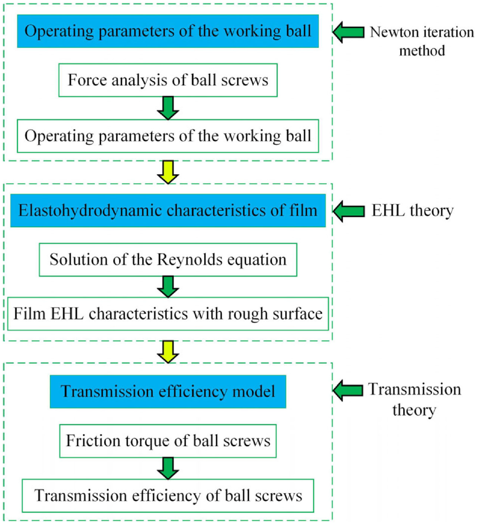
Flowchart of a transmission efficiency model of ball screws.
Determination of the dynamic parameters of the working ball
The ball screws are composed of the screw, balls, and nuts, whose force and velocity are often different. Thus, it is necessary to construct the coordinate system of ball screws (Figure 2(a)).
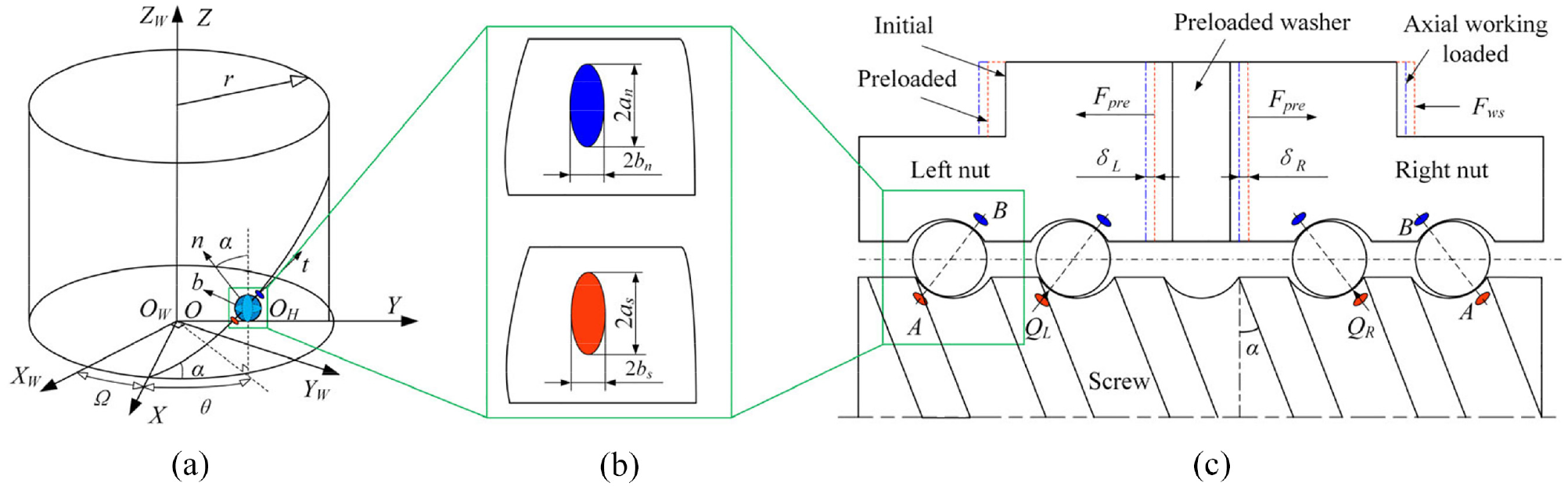
Force and deformation analysis of ball screws: (a) coordinates systems of ball screws, (b) contact regions of the ball/screw-raceway and ball/nut-raceway, and (c) force and deformation analysis of ball screws.
The coordinates system OWXWYWZW can be established in space with its ZW-axis conforming to the axial direction of the screw. Coordinates system OXYZ rotates with the angle Ω as the screw. The X-axis is intersected with the helix track of the ball center, and the t-axis is coincident with the axial direction of the screw. The Frenet-Serret coordinates system OHtnb can be indicated by any point in the helix track of the ball center with the angle θ as the ball. The origin OH is located in the helix track of the ball center, and the t-axis, n-axis, and b-axis vary with the position of the helix track of the ball center. In the system, n is the main normal direction, b is the binormal direction, and t is the tangential direction of the helix.
When the ball screws work in the quasi-static state (constant speed), the working balls are influenced by force and torque, such as normal contact force, inertia force, friction, inertia torque, and friction torque. In terms of the ball force state, the force balance equation and torque balance equation of the working ball are expressed as
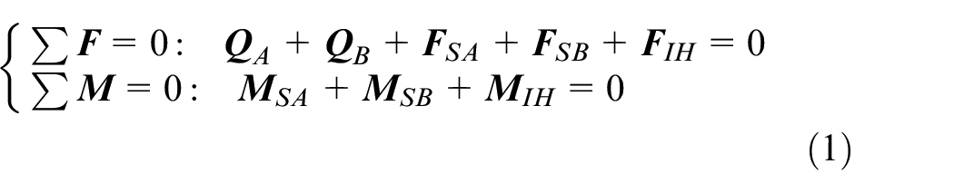
Where QA and QB indicate the normal contact force of the ball at point A and point B, respectively. FSA and FSB denote the friction of the ball at point A and point B, respectively. FIH is the inertia force. MSA and MSB are the friction torque of the ball at point A and point B, respectively. MIH is the inertia torque. The parameters of DNBSs in the operating state, such as βA, βB, QA, QB, FSA, and FSB, are determined by equation (1) using Newton iteration method. The detailed calculation process for the parameters of DNBSs can be found in the reference. 21
Relationship of the raceway normal contact force and axial working load (AWL)
The normal contact forces of the ball between the ball/screw-raceway and the ball/nut-raceway are determined by the preload and AWL, and the contact forces in the left nut and the right nut are different. The contact deformation and force analysis for the DNBSs under the AWL is shown in Figure 2.
The normal contact force of the ball is dependent on the preload and AWL, as shown in Figure 2(c). When the ball screws are only loaded by the preload Fpre, the normal contact forces of the ball in the right and left nuts are the same, that is, QR = QL. When the ball screws are loaded by the preload Fpre and the axial working load Fws, the normal contact forces of the ball in the right and left nuts are different, that is, QR ≠ QL. The contact angles at contact point B and contact point A in a low-speed operating ball screw are considered to be equal, that is, βB =βA=β. According to the deformation coordination principle, 22 the axial contact recovery deformation of the right nut and the axial contact compressed deformation of the left nut are equal.

The normal contact forces of the ball in the right and left nuts can be determined as
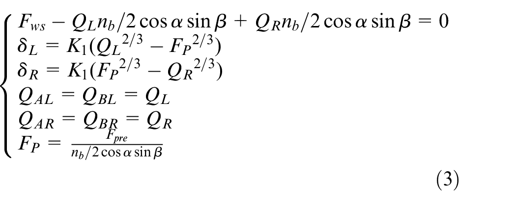
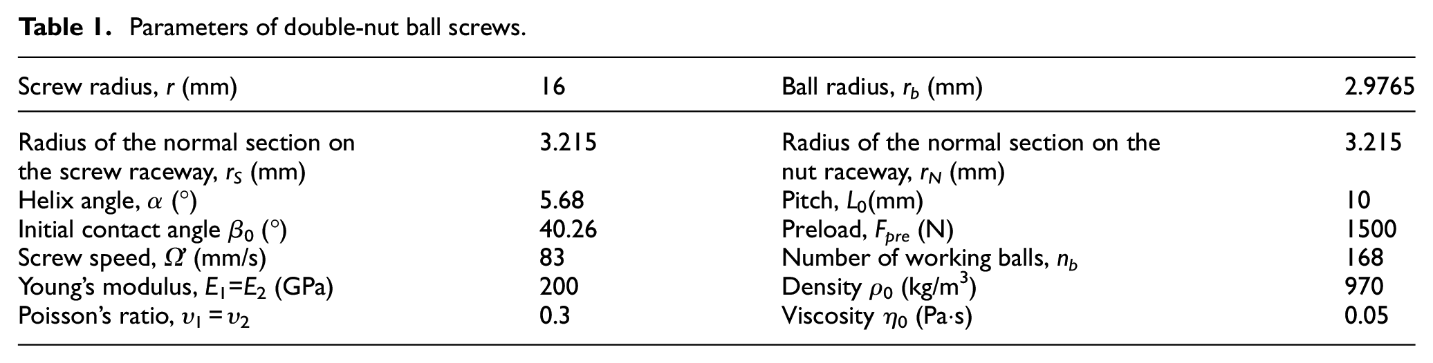
where QR and QL are the normal contact forces of the ball in the right and left nuts, respectively. QAL and QBL denote the normal forces at point A and point B in the left nut, respectively. QAR and QBR denote the normal forces at point A and point B in the right nut, respectively. Fp is the normal contact preload of the ball. α is the helix angle. nb is the number of working balls. K1 is the contact stiffness coefficient, which can be calculated by Hertz theory. 23 The structural parameters of DNBSs are shown in Table 1.
Parameters of double-nut ball screws.
Determination of the EHL characteristics with a smooth surface
To improve the lubrication status in an operating ball screw, the EHL contact problem between the ball and raceway should be solved accurately. The EHL contact model of ball screws under different operation conditions was established, and the film bearing pressure distribution and film thickness distribution were quickly determined.
The basic equation of the EHL contact problem is the RE, 24 which of the ball screws under steady-state, that is, when the contact characteristics do not vary with time, is expressed as
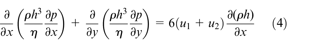
where p is the film bearing pressure in the contact region, and the initial distribution of p can be calculated by Hertz theory. 25 h is the distribution of film thickness (FT) in the contact region, ρ is the density of the oil film, η is the viscosity of the oil film, and u1 and u2 are the velocity of the ball and raceway in the tangential direction of the helix track of the ball center, respectively. The x-direction is the tangential direction of the helix track of the ball center.
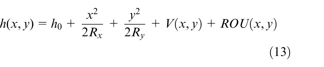
The FT at the contact point of ball screws can be written as
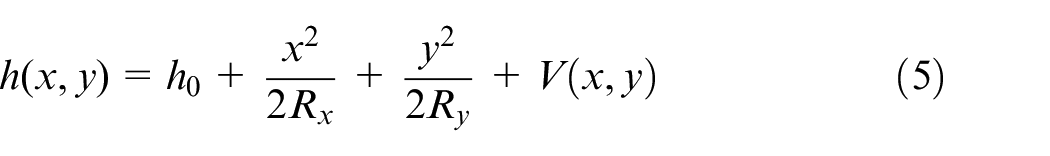
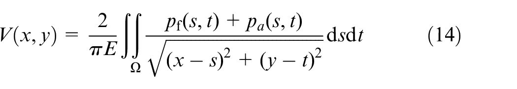
where h0 is the central oil FT in the contact region, Rx and Ry are the equivalent curvature radius of the contact system, respectively, and (Ry/Rx)2/3 = b/a. a and b are the semi-major axis and semi-minor axis, respectively, in the contact region. V is contact deformation distribution in the contact region, 26 which is calculated as
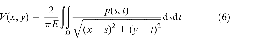
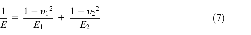
where E1 and E2 are Young’s modulus of the ball and screw/nut, respectively. υ1 and υ2 are Poisson’s ratios of the ball and screw/nut, respectively. Ω is the contact region.
The viscosity 27 of the oil film based on the Roelands formula can be expressed as
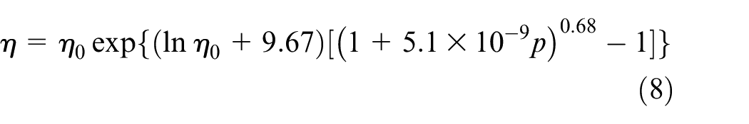
where η0 is the initial value of the oil film viscosity.
The density 28 of the oil film can be expressed as
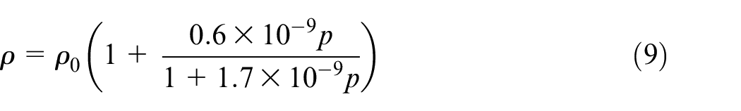
where ρ0 is the initial value of the oil film density.
The boundary conditions of the RE are below:
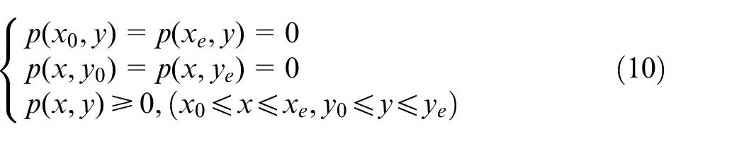
where x0 and y0 are the entrance coordinates of the contact region of ball screws, respectively, and xe and ye are the exit coordinates of the contact region of ball screws, respectively.
The sum of the film bearing pressure in the contact region should be equal to the normal force of the ball. Therefore, the load balance condition of the RE is calculated as follows:
The dimensionless parameters 29 were used in the calculation process of the RE to describe the objective law. The ones of ball screws are written as follows:
where P is dimensionless film bearing pressure distribution in the contact region, US is the dimensionless velocity parameter in the tangential direction of the helix track of the ball center, H is the dimensionless FT distribution in the contact region, us is the entrainment velocity of the oil film, and us=(u1+u2)/2. ρ* is the dimensionless oil film density, η* is the dimensionless oil film viscosity, and Y and X are the dimensionless coordinates of the contact region of ball screws, respectively.
By substituting Equations (5), (6), (7), (8), and (9) into equation (4) and combining the boundary condition and the load balance condition, the RE of ball screws can be accurately solved by the finite difference method. The nonlinear equations of the dimensionless film bearing pressure distribution P and dimensionless film thickness distribution H were obtained by discretized RE based on the finite difference method, 30 and the results were determined by the Newton-Raphson method. 31 The flowchart for the computation of the RE of ball screws is shown in Figure 3.
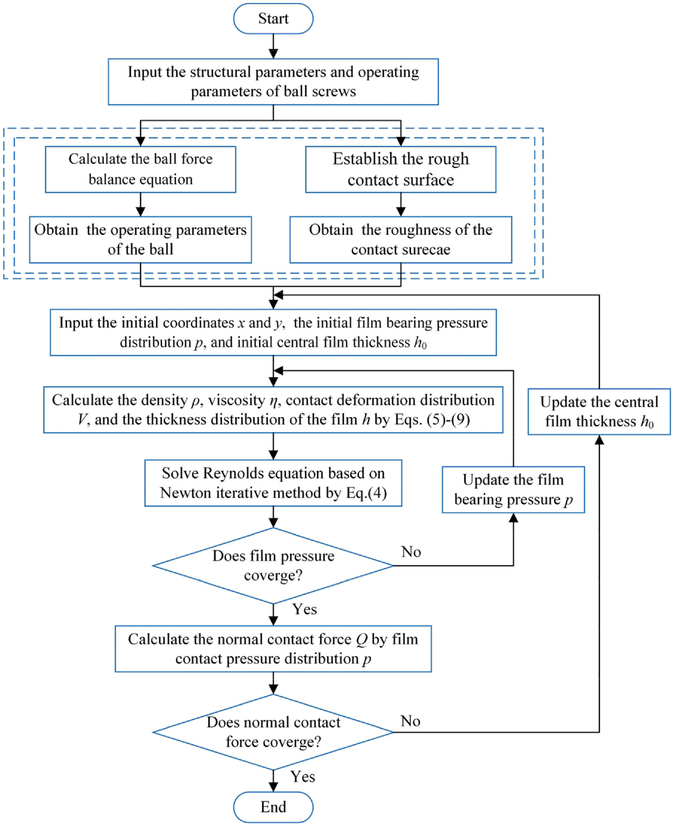
Flowchart for the computation of the RE with a rough raceway surface.
Determination of the EHL characteristics with a roughness surface
Since the surfaces of the ball and raceway are rough, and the EHL characteristics of the contact system are significantly influenced by the roughness of the contact surfaces, the rough contact surface of ball screws should be established to accurately determine the film contact pressure distribution and FT distribution. Since the processing technology of the ball is mature, the contact surface of the ball can be considered smooth. The raceway rough contact surface ROU(x,y) was modeled based on fractal theory, 32 as shown in Figure 4(a). The surface roughness used in the simulation is determined from the experimental measurement based on the structure function method. 33 The fractal parameters of the raceway surface are determined: Ds = 2.68, G = 0.97 × 10⁻⁹.
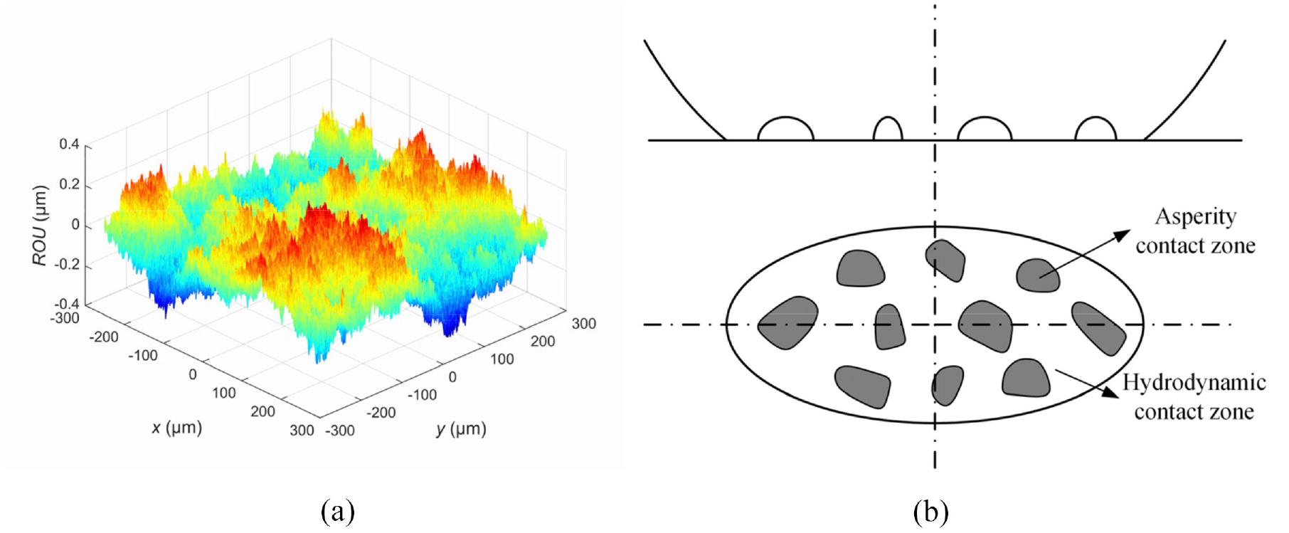
(a) The fractal rough contact surface of raceway with Rq = 0.12 μm and (b) Contact pressure distributions of the film and asperity.
The fractal parameters of the rough fractal surface are calculated based on the experimentally measured raceway surface profile, and the roughness of the rough fractal surface is the same as the roughness of the experimentally measured surface. Therefore, the real raceway surface can be indicated with the rough fractal surface.
We calculate the FT distribution 30 in the rough contact region based on the formula below
The contact deformation distribution in the contact region is calculated as
where pf and pa are the film bearing pressure distribution and asperity bearing pressure distribution, respectively. p is the sum of the film bearing pressure distribution pf and the asperity bearing pressure distribution pa, that is, p = p f +pa. The contact system between the ball and the rough raceway surface is shown in Figure 4(b).
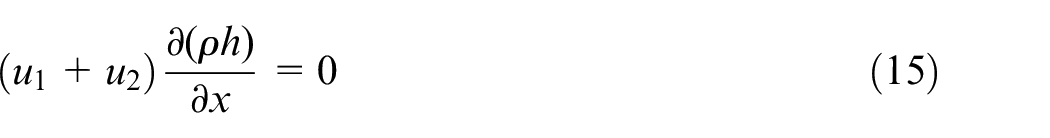
The description of the RE represents a balance of fluid flow. The right-hand side indicates the oil flowrate driven by surface motion in the tangential direction, and the left-hand of the RE is the oil flowrate driven by the hydrodynamic pressure. When the FT is zero, the film bearing pressure pf vanishes, and the asperity bearing pressure pa is generated. The RE is reduced to equation (15).
By substituting equations (7), (8), (9), (13), and (14) into equations (4) and (15), and combining the boundary condition and the load balance condition, the RE of ball screws can be accurately solved by the finite difference method. The flowchart for the computation of the RE under certain roughness of ball screws is shown in Figure 3.
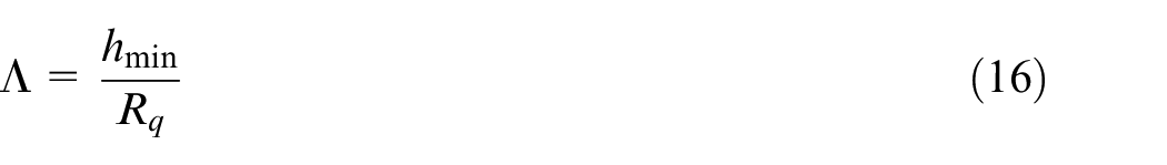
The lubrication status of ball screws can be indicated with the film thickness ratio Λ. If Λ < 1, the contact system is in a boundary lubrication status. If 1 < Λ < 3, the contact system is in a mixed lubrication status. If Λ > 3, the contact system is in a hydrodynamic lubrication status. The film thickness ratio can be expressed as
Modeling of transmission efficiency of DNBSs
The transmission efficiency of DNBSs is the ratio of the screw output power to screw input power when the nut is driven by the screw to move axially. The transmission efficiency 34 is written as
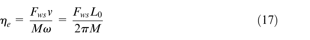

where v is the axial velocity of the nut and ω is the screw input angle velocity. M is the input driving torque of the DNBSs, and MSR and MSL are the friction torque in the right and left nuts, respectively. ML and MR are the torque generated by the normal contact forces in the left and right nuts, respectively, which can be written as
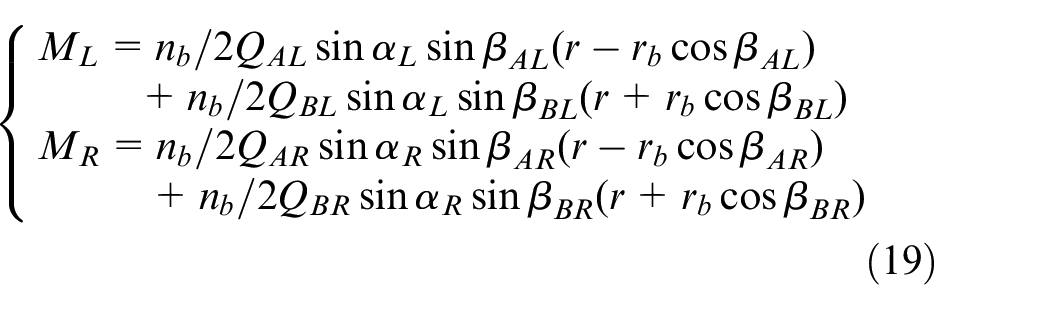
where QAL, QBL and QAR, QBR denote the normal contact forces at point A and point B in the left and right nuts, respectively. αR and αL denote the helix angles in the right and left nuts, respectively. βAL, βBL and βAR, βBR denote the contact angles at point A and point B in the left and right nuts, respectively.
Experiments and verification
To validate the correctness of EHL contact characteristics, the friction torque of ball screws was considered when the verification index was measured. The friction torque test was designed and implemented on a self-designed bed, and the results verified the correctness of the proposed model.
Experimental procedures
The experimental setup of ball screws is shown in Figure 5. The driving torque of the motor was measured by the torque sensor, which was installed between the motor and the screw. When the preload was applied and the AWL was zero, the EHL test of the ball screws was implemented. The driving torque was measured under different entrainment velocity conditions. The simulated friction torque of ball screws can be written as
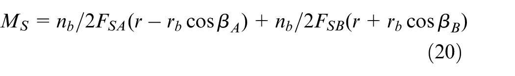
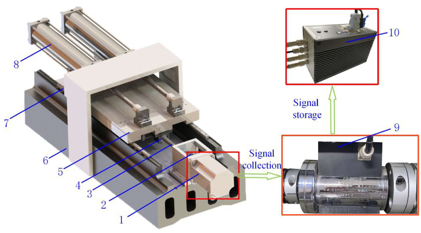
Experimental setup of ball screws: 1. motor, 2. coupling, 3. screw, 4. nut, 5. table, 6. base, 7. guideway, 8. bidirectional cylinder, 9. torque sensor, and 10. computer.
Experimental results
The friction coefficient 35 of ball screws can be written as
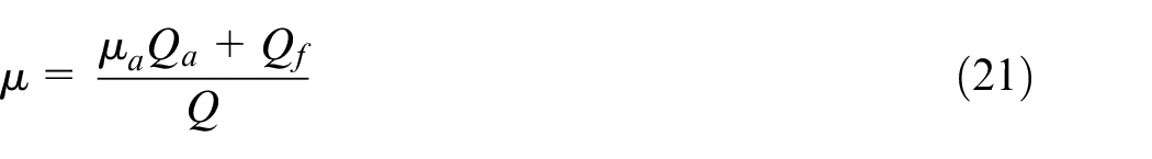
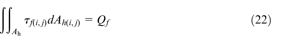
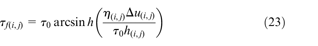
where Q is the total normal contact force, including the film bearing force Qf,, and the asperity bearing force Qa. The ratio of the asperity bearing pressure is RCS, RCS = Qa/Q. μa is the dry friction coefficient and μa = 0.1. τf is the film shear stress proposed by the Eyring model. 36 Ah is the film hydrodynamic contact area, η is the oil film viscosity, Δu(i,j) is the inhomogeneous relative sliding velocity distribution, and Δu = u1(i,j)−u2(i,j). h0 is the film central thickness.
The friction coefficient is one of the input parameters of the ball force balance equation (1). The friction coefficient of ball screws calculated by equations (21)–(23) is used to obtain the friction torque of ball screws by equation (1). The initial friction coefficient μ of ball screws in equation (1) is given, which is satisfied with the lubrication operating condition.
The driving torque is equal to the friction torque of ball screws when only the preload is applied. The measured periodic driving torque of ball screws under an entrainment velocity of 837.75 mm/s is shown in Figure 6(a), and the values of driving torque are different in the forward and reverse operating states. Therefore, the measured driving torque was averaged under different entrainment velocities.
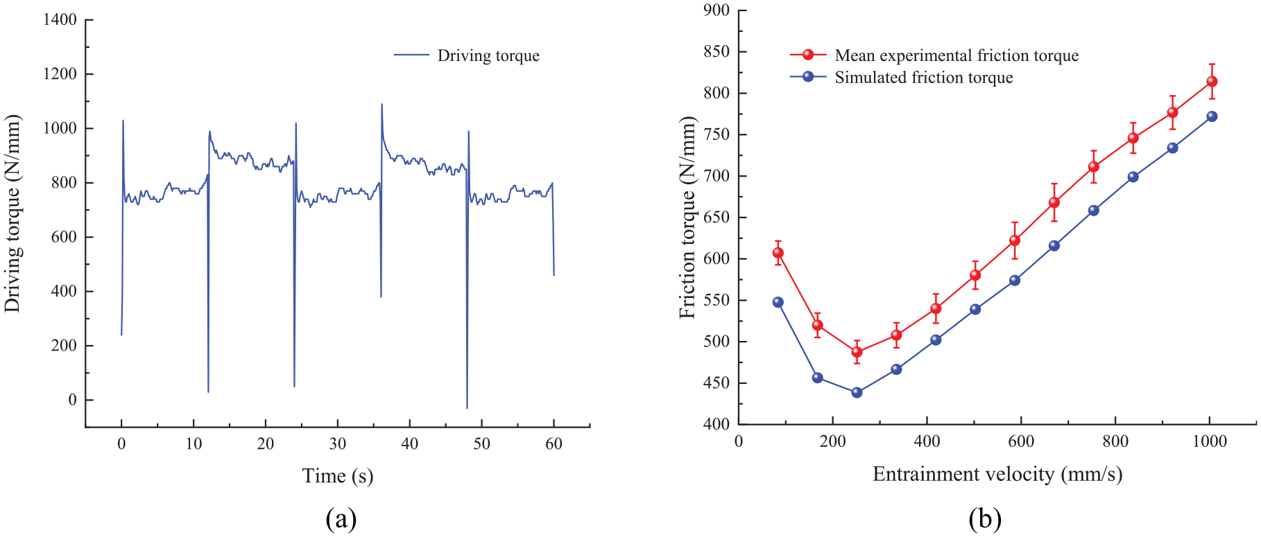
Results of the friction torque test: (a) friction torque measured at 837.75 mm/s and (b) comparison of the simulated and experimental friction torque.
The experimental friction torques of ball screws are measured from multi-group experiments. The error bars of the experimental friction torques under different entrainment velocities are shown in Figure 6(b). The simulated and experimental friction torque decreased first and then increased as the entrainment velocity increased. The simulated friction torque was slightly lower than the experimental friction torque. The maximum error and minimum error between the simulated friction torque and experimental friction torque are 12.8% and 2.6%, respectively. The errors of the friction torque of ball screws meet the actual engineering requirement. Therefore, the experimental results verified the correctness of the elastohydrodynamic contact characteristics.
Results analysis and discussion
Analysis of EHL characteristics with a smooth surface
When the preload of ball screws is applied and AWL is zero, the EHL characteristics of oil film with a smooth surface are shown in Figure 7. As shown in Figure 7(a), the central bearing pressure of the film reduces as raised entrainment velocity. The secondary peak of the film bearing pressure is generated in the outlet of the contact region, and its value increases as raised entrainment velocity. Furthermore, the secondary peak is greater than the central bearing pressure when the entrainment velocity is increased to a certain extent. The FT increases as the entrainment velocity in the contact region increases, and the minimum of FT is generated in the second peak of film bearing pressure.
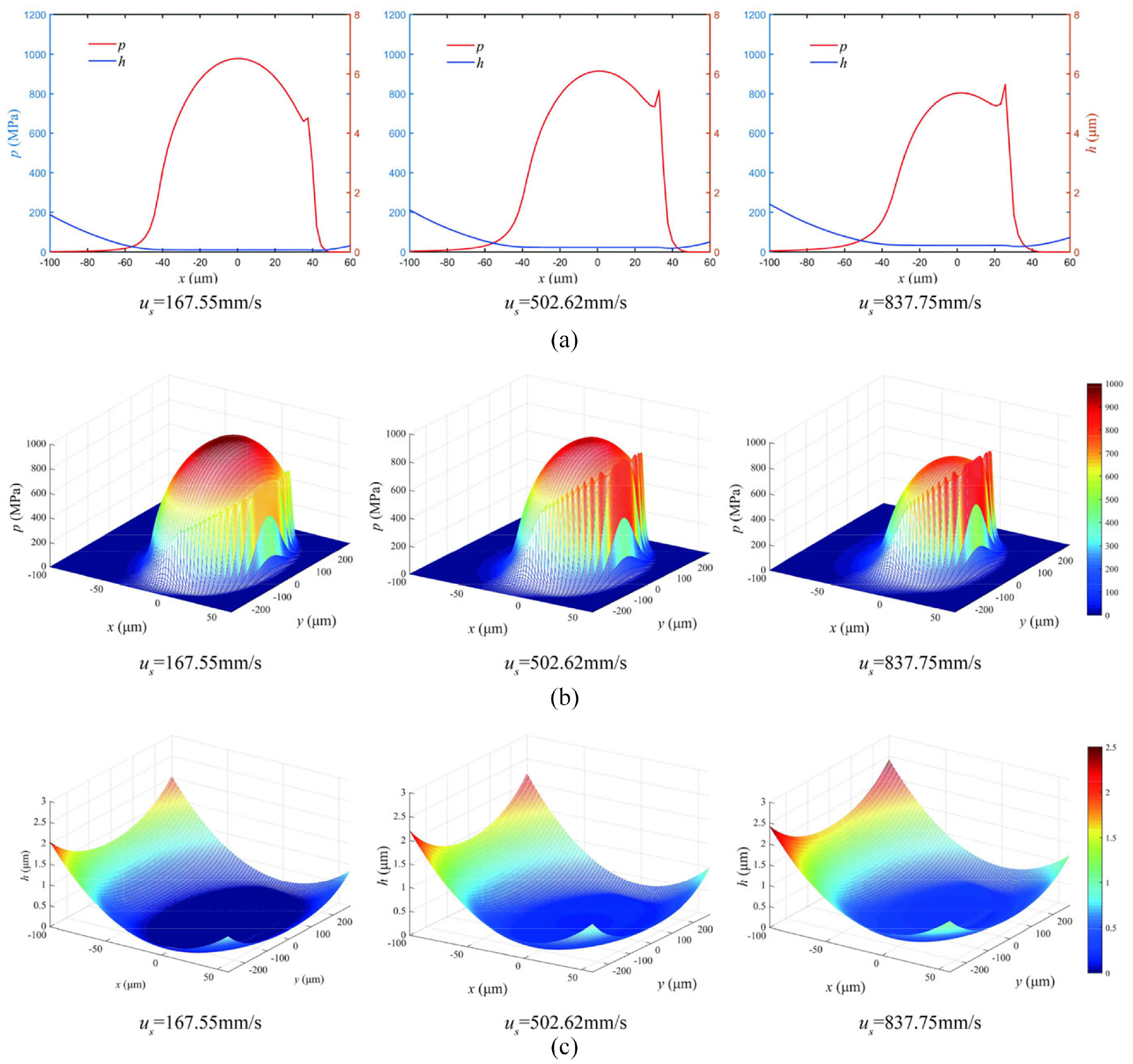
EHL characteristics of oil film with a smooth surface: QA = 27.6N: (a) 2D curves of film bearing pressure and film thickness, (b) 3D distribution of film bearing pressure, and (c) 3D distribution of film thickness.
Figure 7(b) and (c) show the three-dimensional (3-D) distributions of the film bearing pressure and FT.
When the preload and AWL of DNBSs are applied under a constant entrainment velocity, the force states of the left nut and right nut are different, and the elastohydrodynamic film characteristics of the left nut (with a smooth surface) at point A under diverse AWLs are shown in Figure 8. Figure 8(a) shows that the central bearing pressure, secondary bearing pressure peak, and FT increase as the normal contact force increases. Figure 8(b) and (c) show the 3-D distributions of the film bearing pressure and FT.
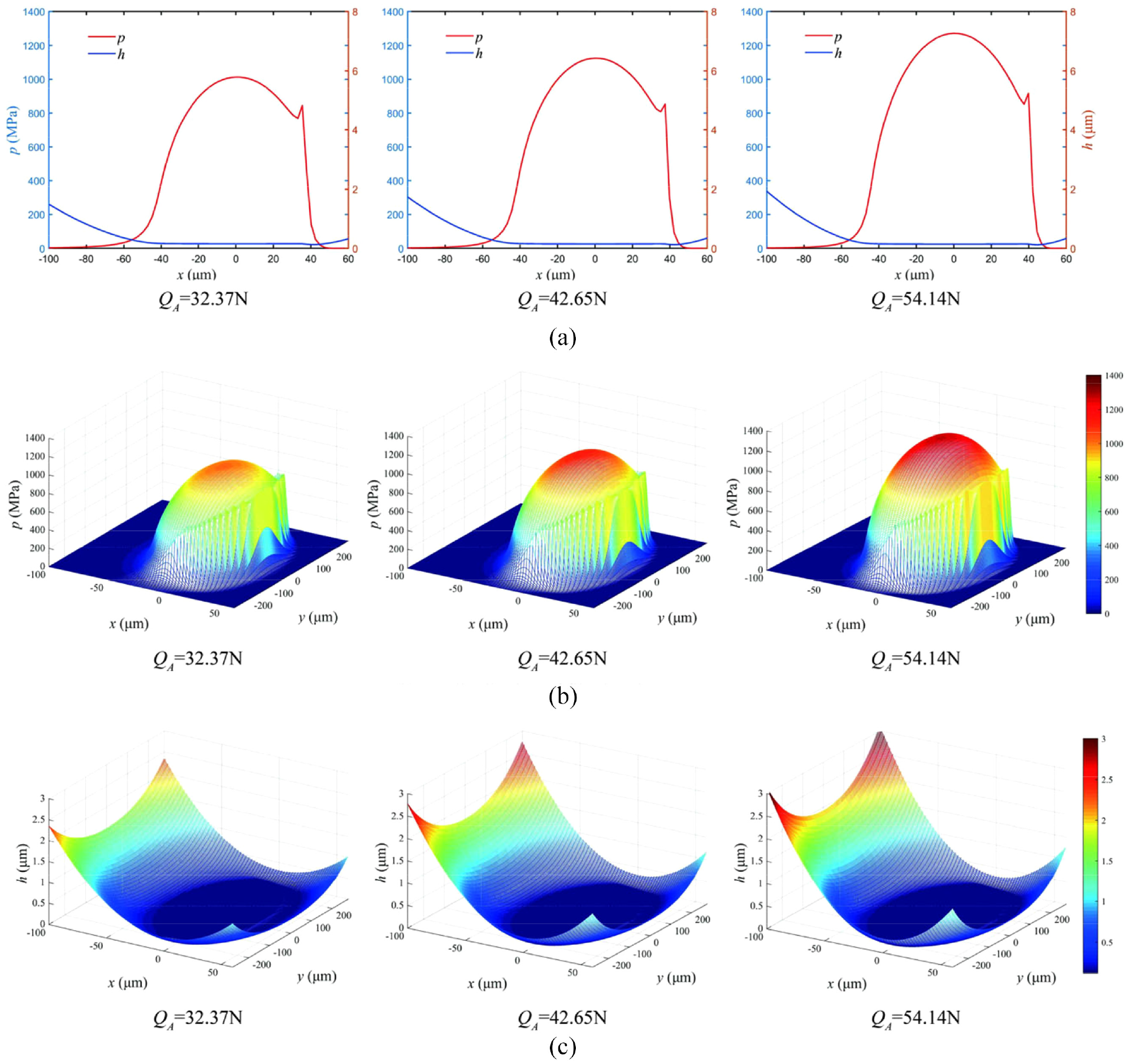
EHL characteristics of oil film with a smooth surface: μe = 502.62 mm/s: (a) 2D curves of film bearing pressure and film thickness, (b) 3D distribution of film bearing pressure, and (c) 3D distribution of film thickness.
Analysis of EHL characteristics with a rough surface
When the preload of ball screws is applied and the axial working load is zero, the EHL characteristics of oil film with a rough surface are shown in Figure 9. Figure 9(a) shows that due to the high asperities of the rough surface, the maximum film bearing pressure on the rough surface is greater than that on the smooth surface. The FT of asperity contact zone is zero, and the area of asperity contact zone decreases as raised entrainment velocity. The reason is that the average film thickness increases as raised entrainment velocity. Other EHL characteristics obtained with the rough surface are the same as those obtained with the smooth surface. The film is punctured by the asperities concentrated in the central contact region because the central contact pressure is higher than that of other contact regions when the normal contact force increases. Figure 9(b) and (c) show the 3-D distributions of the film bearing pressure and FT.
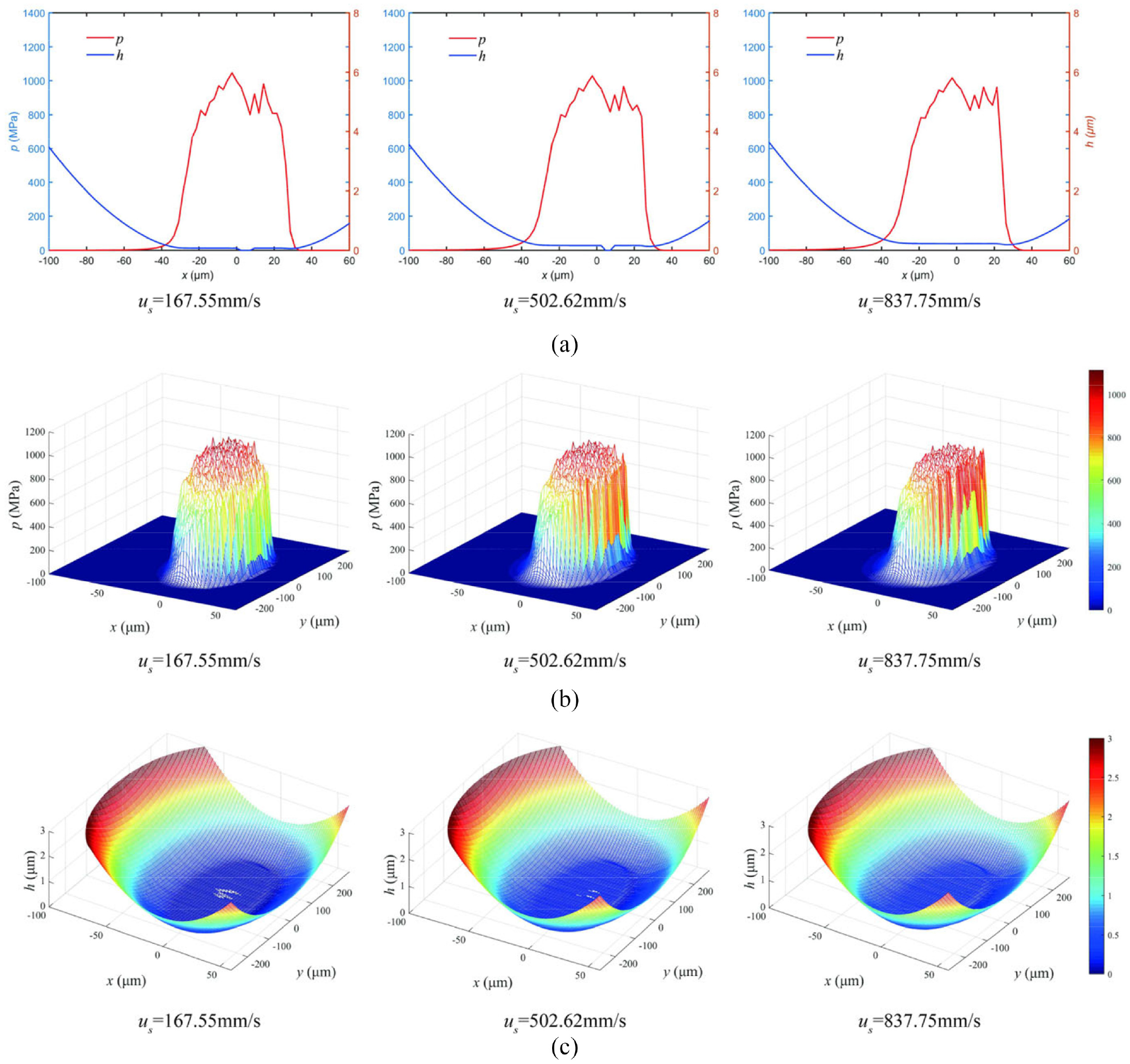
EHL characteristics of oil film with a rough surface: Rq = 0.12 μm, QA = 27.6N: (a) 2D curves of film bearing pressure and film thickness, (b) 3D distribution of film bearing pressure, and (c) 3D distribution of film thickness.
When the preload and AWL of DNBSs are applied under a constant entrainment velocity, the EHL film characteristics of the left nut (with a rough surface) at point A under diverse AWLs are shown in Figure 10. Figure 10(a) shows that the central bearing pressure, secondary bearing pressure peak, and thickness of oil film increase as the normal contact force increases. The asperity zone becomes gradually closer to the center of the contact region, which can be seen clearly from Figure 10(a) and (c). Figure 10(b) and (c) show the 3-D distributions of the film bearing pressure and FT.
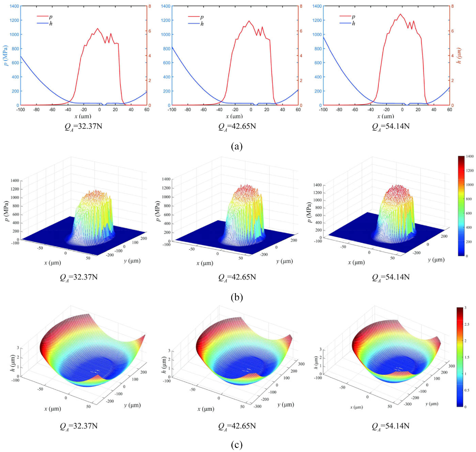
EHL characteristics of oil film with a rough surface: Rq = 0.12 μm, μe = 502.62 mm/s: (a) 2D curves of film bearing pressure and film thickness, (b) 3D distribution of film bearing pressure, and (c) 3D distribution of film thickness.
Analysis of the lubrication status and friction coefficient (FC)
The FC of ball screws is elucidated clearly in Figure 11. As shown in Figure 11(b), the simulated FC of ball screws is indicated by the blue line, which is in good agreement with the schematic Stribeck curve 37 shown in the green box (Figure 11(a)). The simulated FC decreases first and then increases with the entrainment velocity. On the one hand, the asperity FC decreases as raised entrainment velocity. On the other hand, the elastohydrodynamic FC increases as raised entrainment velocity. The reason is that the FT increases with the entrainment velocity shown in Figure 11(c), and more oil is entrained in the contact region. The FT h under 502.65 mm/s is 0.153 μm, and the roughness Rq of the contact surface is 0.12 μm. When h <3R q , the contact system is in a mixed lubrication status. When h ≥ 3R q , the hydrodynamic lubrication is generated in the contact system.
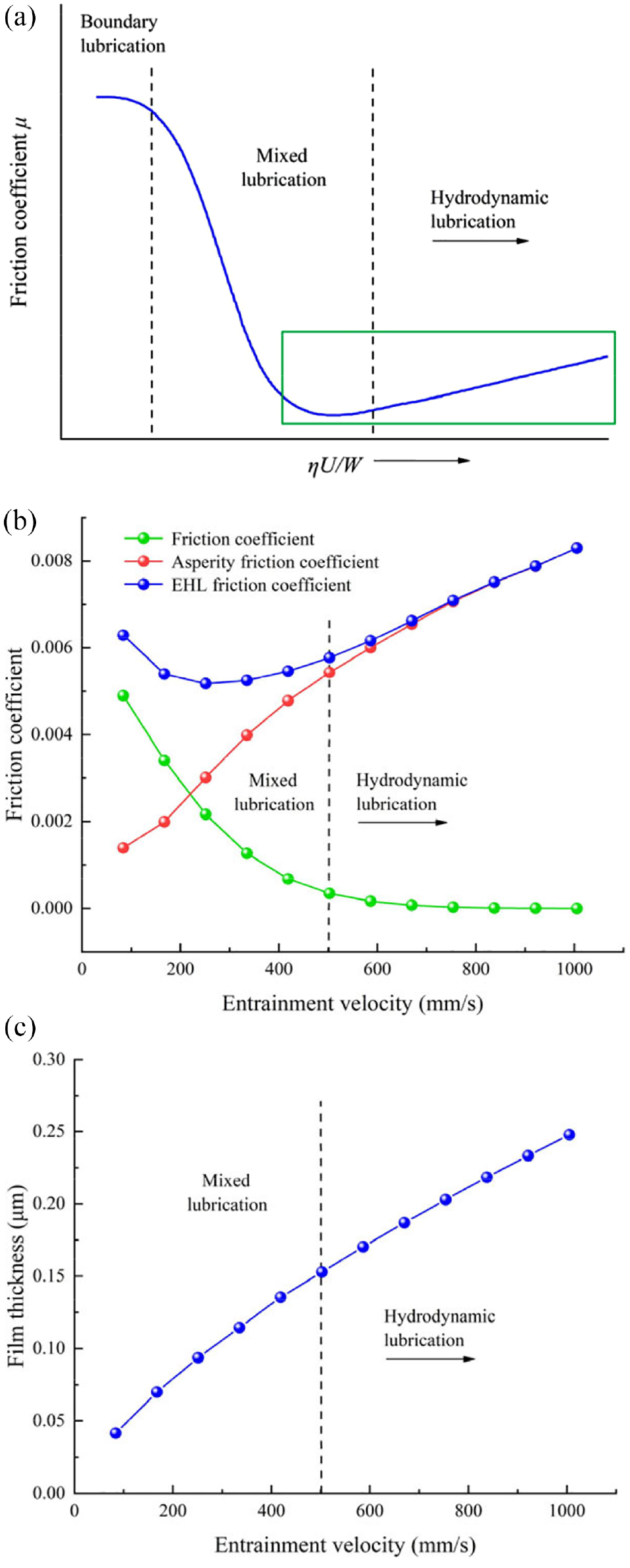
Friction coefficient curve: (a) a schematic Stribeck curve, (b) friction coefficient curve, and (c) film thickness curve.
Transmission efficiency analysis of DNBSs
The positioning accuracy and lubrication status of machine tools are greatly influenced by the transmission efficiency and ratio of the asperity bearing pressure of ball screws under different operating conditions. Therefore, the optimal operating condition of ball screws is of great reference to the green processing and manufacturing fields. The distributions of the ratio of the asperity bearing pressure and transmission efficiency under different operating conditions of ballscrews are shown in Figure 12. Figure 12(a) shows that the ratio of the asperity bearing pressure RCS decreases as raised entrainment velocity and increases as raised AWL, respectively. The transmission efficiency of ball screws increases with the rise of entrainment velocity but increases first and then reduces with the rise of AWL, respectively, as shown in Figure 12(b).
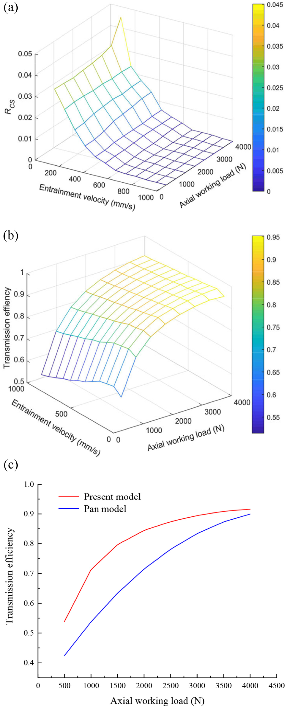
The ratio of the asperity bearing pressure and transmission efficiency of ball screws: (a) the ratio of the asperity bearing pressure, (b) transmission efficiency, and (c) comparison of the transmission efficiency.
The predicated transmission efficiency of the present model is compared with the result predicted by the Pan model, 34 as shown in Figure 12(c). The transmission efficiency calculated by the present model and Pan model both increased with the axial working load. The transmission efficiency determined by the present model is greater than the one predicted by the Pan model. The reason is that the friction coefficient of ball screws calculated by the present model varies with the axial working load, while the friction coefficient of the Pan model is constant. The transmission efficiency calculated by the Pan model cannot reflect the dynamic change of the transmission efficiency. Therefore, the transmission efficiency of ball screws predicted by the proposed model is more accurate.
The lubrication status of ball screws is considered good when the ratio of the asperity bearing pressure is less than 0.01, and the processing efficiency is considered high when the transmission efficiency is greater than 0.85. The optimal operating condition distribution confirming the good lubrication status and high transmission is shown in Figure 13. The operating conditions with RCS , 0.01 are indicated in green, with transmission efficiency ηe ≥ 0.85 denoted in blue. The optimal operating condition with RCS , 0.01 and ηe ≥ 0.85 is shown in red. The optimal operating condition of ball screws can reduce energy consumption, save resources, and further aid the sustainable development of the machine manufacturing industry. Besides, the optimal condition of ball screws acts as a reference for the green processing and manufacturing fields.
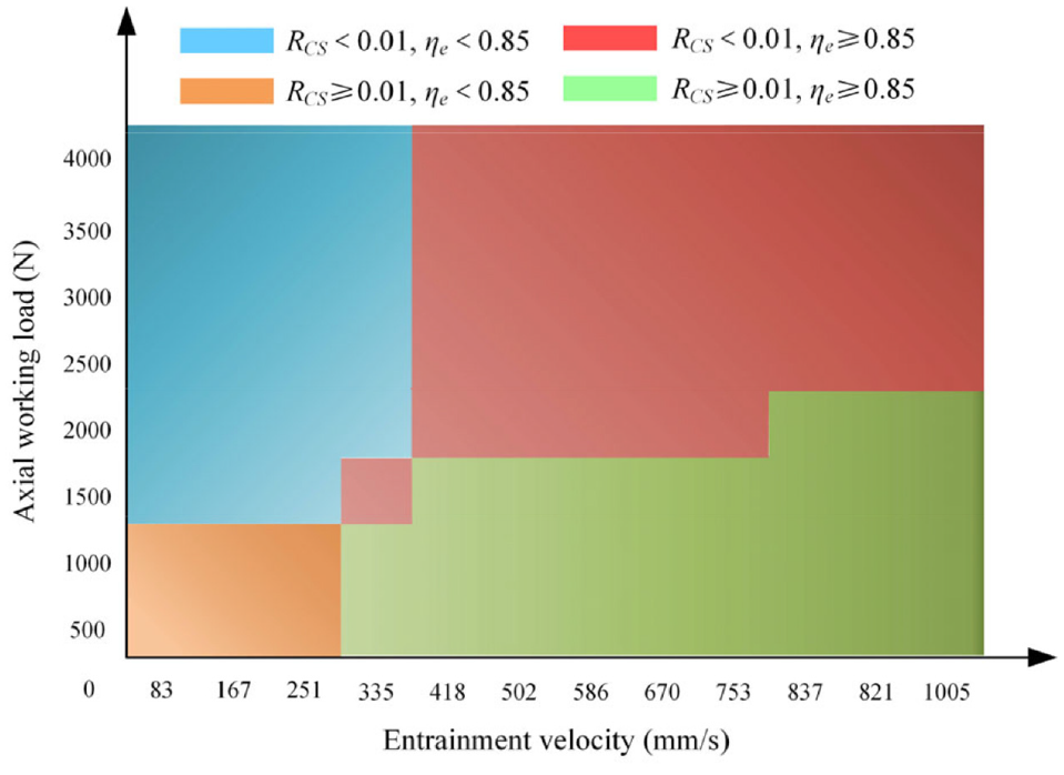
Optimal operating condition of double-nut ball screws.
Conclusions
Based on the modeling of transmission efficiency of ball screws, the conclusions below can be drawn:
Considering the kinematic analysis and lubrication status, a transmission efficiency model was used for determination of the optimal operating condition of the DNBSs to improve manufacturing accuracy and efficiency.
Based on the asperity contact friction coefficient and the oil film shear friction coefficient, the friction mechanism of the ball screws was clearly elucidated from a microcosmic perspective, and the friction coefficient and lubrication status were accurately identified under different operating conditions.
According to the RE, the distributions of film thickness, film bearing pressure, and ratio of the asperity bearing pressure of ball screws were determined to elucidate the friction mechanism, and the correctness of the proposed model was verified by the good agreement of the experimental friction torque of the ball screws with the simulated results.
The application of optimal operating conditions for balls screws contributes to the improvement of workpiece machining efficiency and machining quality, additionally, which can save energy and extends the service life of ball screws with good lubrication. Therefore, the optimal operating conditions of the ball screws are of great reference to green processing and manufacturing fields.
Footnotes
Declaration of conflicting interests
The author(s) declared no potential conflicts of interest with respect to the research, authorship, and/or publication of this article.
Funding
The author(s) disclosed receipt of the following financial support for the research, authorship, and/or publication of this article: This study was sponsored by the National Natural Science Foundation of China (No.: 51975020, 51575014, and 51875008), Beijing Municipal Natural Science Foundation (No.: 3202005), and the International Research Cooperation Seed Fund of Beijing University of Technology (No.: 2021A10).