
Abstract
A gas turbine engine with a sequential combustion system has the potential to offer high cycle efficiency at moderate turbine entry temperatures. Consequently, it has one more degree of power setting control, which offers more flexible but also more complex control of engine off-design operations. In this paper, a novel simulation method for off-design thermodynamic performance of sequential combustion gas turbines has been introduced and a novel performance control schedule for part-load operations at various ambient conditions have been proposed aiming to keep the relative workloads between the two turbine sections constant. The proposed control schedule is simple and can be adapted easily. By applying the off-design performance control schedule to a model industrial gas turbine engine with two sequential combustors, the performance of the model engine is simulated at different part-load and at different ambient conditions. The results show that by applying the proposed off-design performance control schedule, the model sequential combustion gas turbine engine could operate effectively at different part-load operating conditions and at different ambient conditions with both turbine sections keeping nearly constant workload distributions.
Introduction
Modern gas turbine engines are based on Brayton cycle whose T-s diagram is shown in Figure 1(a). The cycle thermal efficiency of the gas turbine engines is mainly dominated by the cycle overall pressure ratio and the turbine entry temperature (TET). The higher the total pressure ratio and TET, the higher the cycle thermal efficiency. However, the conventional Brayton cycle engines seem to have reached their performance limits as the increase of TET is limited by the materials and cooling technology. T-s diagram of gas turbine cycles (a) Conventional Brayton cycle (b) CTTB engine cycle (c) CPTB engine cycle.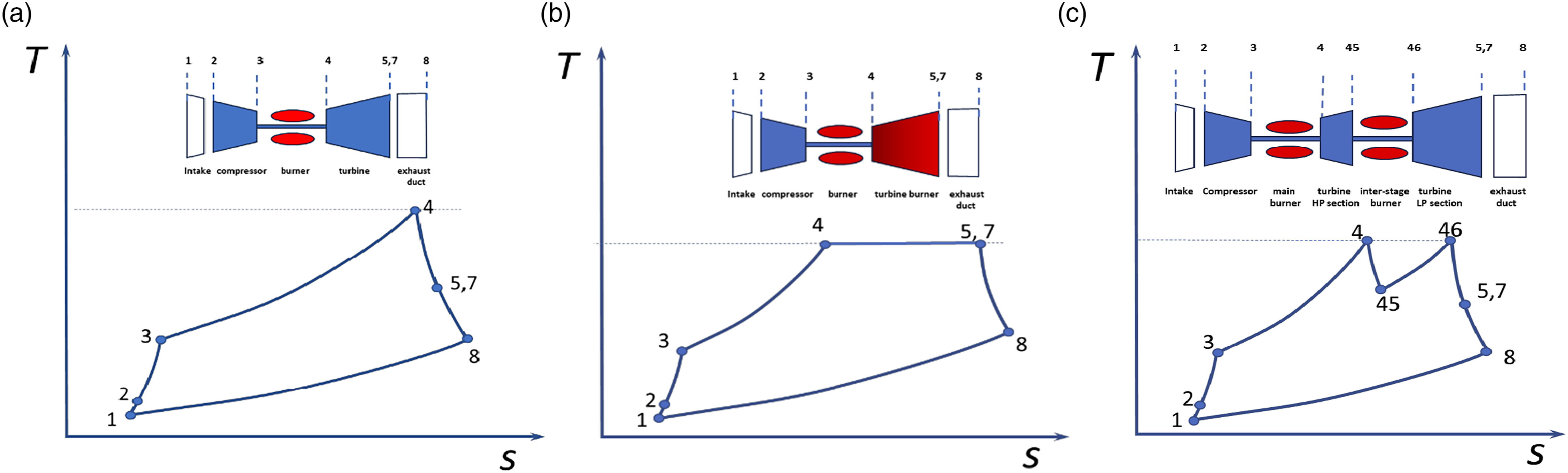
To improve the engine thermal efficiency further, one of the methods is to add extra energy during turbine expansion process known as sequential or reheat combustion while keeping the same maximum temperature throughout the combustion and expansion processes. As summarized by Yin and Rao, 1 there are two ways to apply such a cycle concept. One is to apply a constant temperature turbine burner (CTTB) introduced by Andriani et al. 2 and Andriani and Ghezzi 3 where the combustion happens during the turbine expansion process, to make the cycle closer to Carnot cycle (isothermal heat addition) whose T-s diagram is shown in Figure 1(b). Further research in this direction have been reported by Sirignano and Liu 4 and Sirignano et al., 5 Chiu et al. 6 and Liu and Sirignano. 7 It was concluded that CTTB could produce more specific power and higher efficiency than the conventional gas turbines but the application of CTTB engines is practically challenging as it is difficult to burn fuel within a turbine expansion process. The other one is called Constant Pressure Turbine Burner (CPTB)7–12 where energy is added in additional combustors between turbine stages, that is inter-stage or sequential combustors. When the number of inter-stage combustors is increasing, it will become close to CTTB. Due to the feasibility in practical applications, most research on CPTB focus on gas turbine engines with a single inter-stage combustor whose T-s diagram is shown in Figure 1(c). A comprehensive technology review of gas turbines with inter-stage turbine combustors is provided in 1.
The concept of the gas turbine engines with sequential combustors is practically demonstrated by the GT24/GT26 industrial gas turbine engines9,10 as shown in Figure 2. Due to the increase of O&M costs compared to traditional gas turbine engines, the application of the such gas turbine engines are limited nowadays. However, the benefits of performance improvements could outweigh the increased O&M costs when new demands or new applications of the gas turbine engines with sequential combustors appear in the future.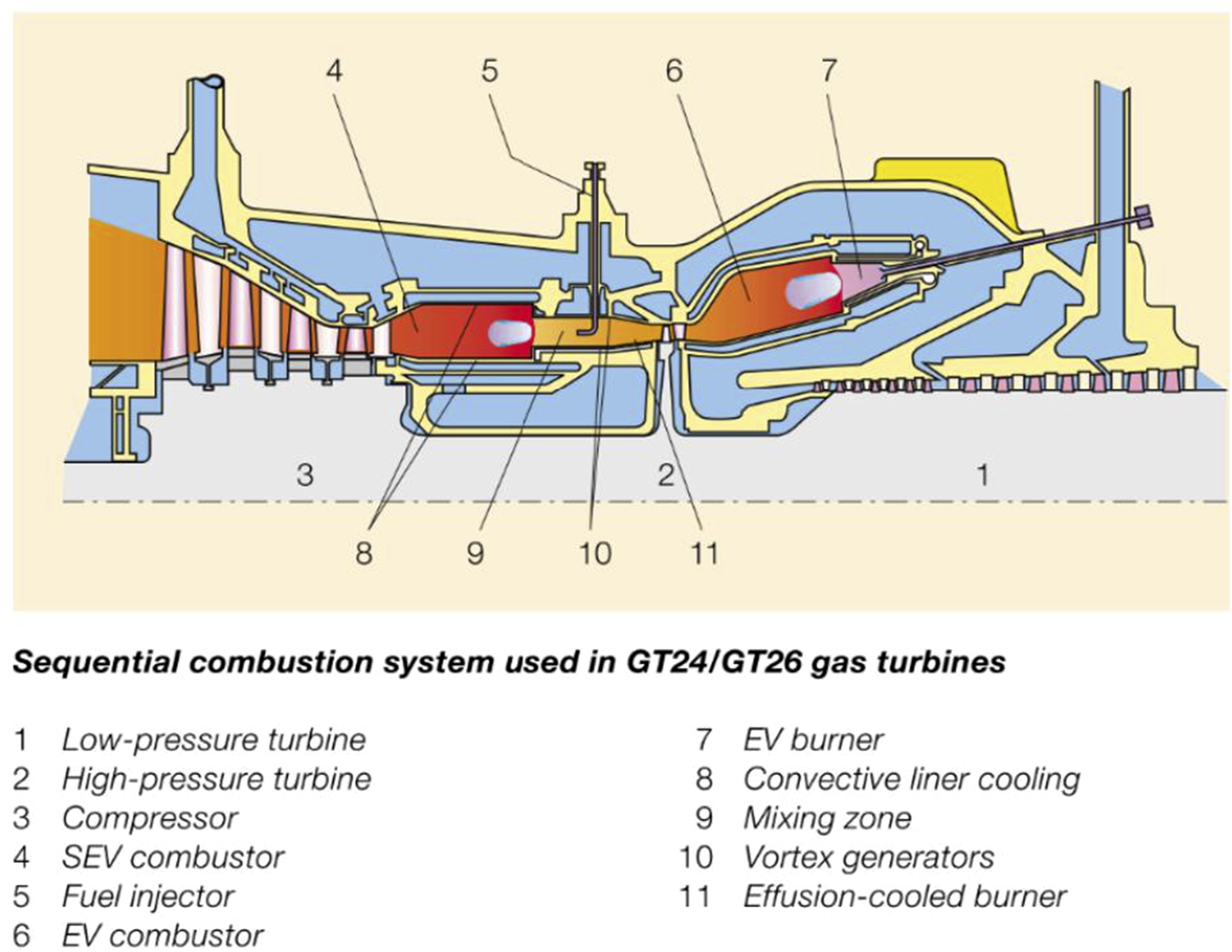
Current gas turbine off-design performance simulation methods, demonstrated by modern software such as PROOSIS, 13 GENENG,14,15 DYNGEM, 16 GasTurb, 17 GSP, 18 C-MAPSS, 19 etc. only provide the simulation capability of gas turbine engines with a single combustor and therefore are not able to simulate the off-design performance of the engines with two sequential combustors. In addition, no publications have been found about off-design performance simulation and control methods for gas turbine engines with sequential combustors.
In this paper, a novel thermodynamic performance simulation method for the off-design performance of industrial single-shaft gas turbine engines with two sequential combustors is introduced. A novel off-design performance control schedule is proposed with an objective of controlling the gas turbine off-design operations effectively and keeping the relative workload distribution between the two turbine sections constant for the benefits of good aerodynamic performance and balanced creep life consumption of the turbine sections. In addition, the proposed performance simulation method and the off-design performance control schedule are applied to a model gas turbine engine with two sequential combustors to demonstrate the effectiveness of the proposed method. Predicted performance of the model gas turbine engine, in particular the turbine entry temperatures of the two turbine sections, the workload distribution between the two turbine sections, the compressor IGV angle, and the engine thermal efficiency are shown and discussed, and conclusions are presented.
Methodology
This section introduces a novel thermodynamic performance simulation method and a new off-design performance control schedule for single-shaft industrial gas turbine engines with two sequential combustors represented by Figure 3. Model gas turbine with sequential combustors.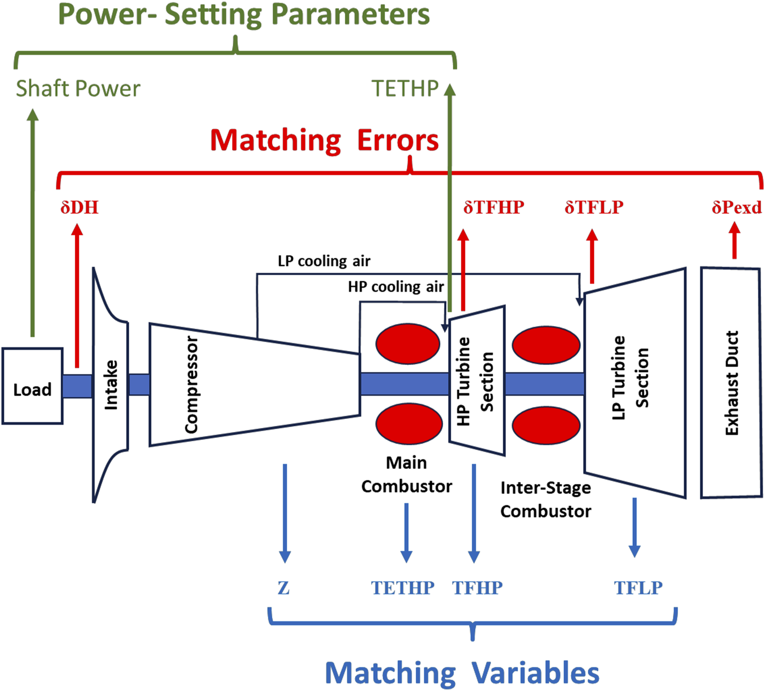
Gas turbine off-design performance simulation approach
The off-design performance simulation approach proposed in this paper is an extension of the performance simulation approach based on thermodynamics for conventional gas turbines where the details can be found in 20. The corresponding software, Turbomatch 20 and Pythia 21 have been developed at Cranfield over the past half century and validated against real engine data.22,23 Due to that sequential combustion engines have one more combustor resulting in the engine systems having one more dimensional of freedom, the off-design performance simulation approach has to be modified to deal with such complexity.
Performance simulations of a gas turbine engine normally start from the setting up of a performance model at a specified design operating condition where the configuration of the engine is decided and the component design parameters, such as compressor pressure ratio, turbine entry temperatures (TET), total air flow rate, power output, component efficiencies, pressure losses, cooling air flows, etc are given as input. Then, the design-point performance simulation can be conducted where the size of the engine and its components are determined, and the whole engine thermodynamic performance are calculated. This provides a starting point for the off-design performance simulations.
The off-design thermodynamic performance of the gas turbine engines refers to the performance of the gas turbine engines operating at different ambient and part-load operating conditions where the characteristics of the major components, including compressors, combustors and turbines represented by component maps play a crucial role in engine performance behaviour. When an engine moves from one operating condition to another, the engine has to adapt itself to a new equilibrium condition where the conservation of mass and energy throughout the engine has to be satisfied. The control parameters that determine the operating conditions of the engine are called power setting parameters or handle parameters, such as shaft rotational speeds, turbine entry temperatures, shaft power output, etc. There is only one power setting parameter for conventional gas turbine engines. However, there are two power setting parameters for sequential combustion engines due to the adding of the 2nd combustor in the system.
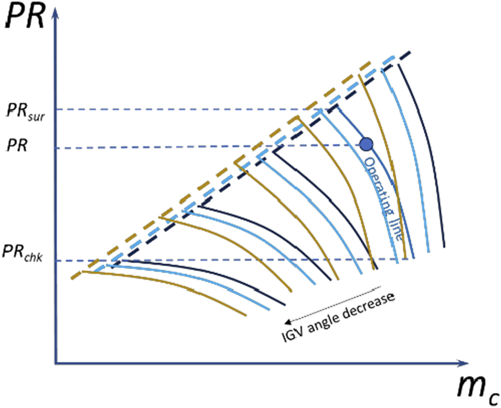
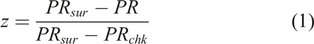
To achieve the conservation of mass and energy in off-design performance calculations, the following two sets of parameters are normally identified for the engine thermodynamic system. The first one is a set of matching variables that determine the thermodynamic status of the gas turbine engine, including • Variable z defined by Eq. (1) that specifies the relative position of the operating point on the relevant speed line of a compressor map. • Turbine Entry Temperature (TET) • Shaft relative rotational speed PCN of compressor defined as the ratio between the shaft rotational speed at any operating condition and the shaft rotational speed at design operating condition where • Shaft power output • Non-dimensional mass flow rate Characteristic map of compressor with variable IGV.
The second set of parameters is the matching errors of the gas turbine engines that are used to assess the conservation of mass and energy within the whole engine systems, including • Error δm
c
of compressor mass flow defined by Eq (2) as the difference between the actual mass flow rate m
c
coming from the upstream of a compressor and the mass flow rate that can be swallowed by the compressor obtained from the compressor map m
c,map
• Error δTF of turbine non-dimensional mass flow rate TF defined by Eq. (3) as the difference between the actual non-dimensional mass flow rate coming from the upstream of a turbine and the non-dimensional mass flow rate that can be swallowed by the turbine obtained from the turbine map TF
map
• Error δDH of turbine enthalpy drop defined by Eq. (4) as the difference between the actual work DH that all turbine sections on the same shaft should jointly deliver, including the work consumed by compressors and the auxiliary systems on the same shaft, and the work DH
map
that all turbine sections can deliver which is the summation of the work obtained from each map of all turbine sections • Error δP
exd
of exhaust duct to measure the mass continuity at the exhaust duct, defined by Eq. (5) as the difference between the total pressure P
exd
of in-coming mass flow of a exhaust duct and the total pressure P
req
needed to drive the in-coming mass flow through the exhaust duct


Not all of the above matching variables and errors are required for the off-design performance calculations of all gas turbine engines. The selection of them depends on the type of engines, the selection of power setting parameter(s) and the off-design performance control schedule. To ensure a unique solution at an off-design operating point, the number of matching variables denoted as N
V
must be equal to the number of matching errors, denoted as N
E
, represented by Eq. (6).

Figure 3 shows the gas turbine engine in concern with a set of matching variables, a set of marching errors and a set of power setting parameters. More discussions on the selection of these parameters will be given in the next section.
As a gas turbine engine is a non-linear and complex thermodynamic system, the matching errors
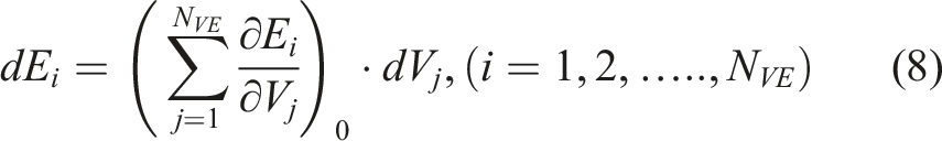
A solution may be obtained by solving Eq. (8) and the new values of the matching variables may be obtained by Eq. (9).

Because of the non-linearity of engine performance behavior, the solutions from the linearized Eq. (8) may have large prediction errors. Therefore, Newton Raphson iterative approach shown in Figure 5 may be applied to get a converged solution when the matching errors become significantly small. It is worth mentioning that under-relaxation may be used in the Newton Raphson iteration process in order to enhance the convergence of the predictions. Newton Raphson iterations.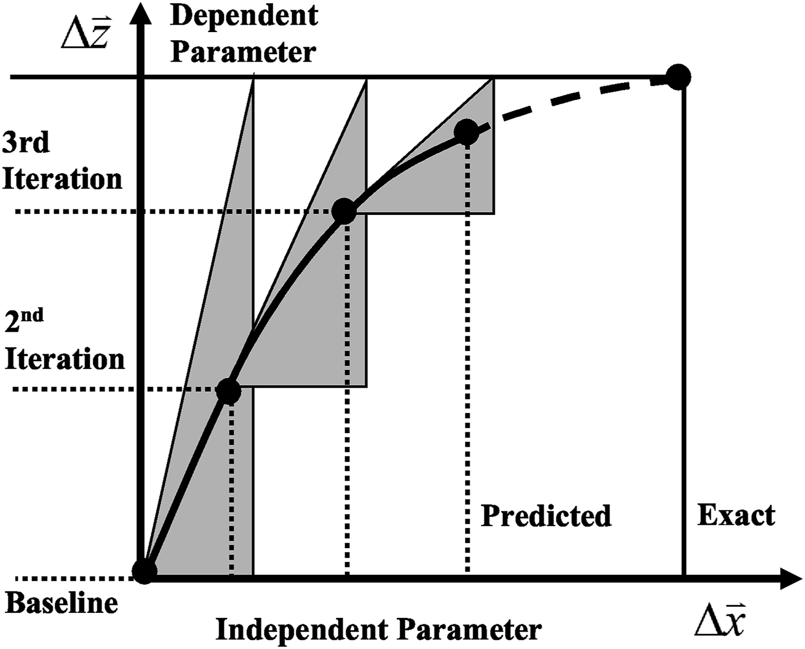
Off-design performance control strategy
As stated in the early sections, a sequential combustion gas turbine engine shown in Figure 3 has two power setting parameters due to the addition of an extra inter-stage combustor. This results in more flexibility but also more complexity in engine off-design performance control compared with conventional gas turbine engines having only one power setting parameter.
The two power setting parameters may be chosen from the following parameters: • Turbine shaft power output ( • Shaft relative rotational speed (PCN) • Turbine entry temperature of the turbine HP section (TETHP) • Turbine entry temperature of the turbine LP section (TETLP)
For a single-shaft industrial gas turbine engine with sequential combustors, the selection of the power setting parameters in two special scenarios may be considered: • The operation of the engine is to meet the external power demand. Therefore, the turbine shaft power output ( • If the engine is used for electricity power generation, the engine may be connected to a national grid via a gearbox so the shaft rotational speed must be kept constant to ensure output speed at either 3000 rpm or 3600 rpm depending on the frequency of the grid. Therefore, the shaft rotational speed at part-load operating conditions should be kept constant and cannot be used as a power setting parameter.
With the above considerations in mind, the following two off-design performance control schedules are investigated and their impact on engine performance are simulated and analyzed:
Control schedule 1:
– TETHP control
With this control schedule, Off-design control schedule – TETHP & TETLP varying with shaft power.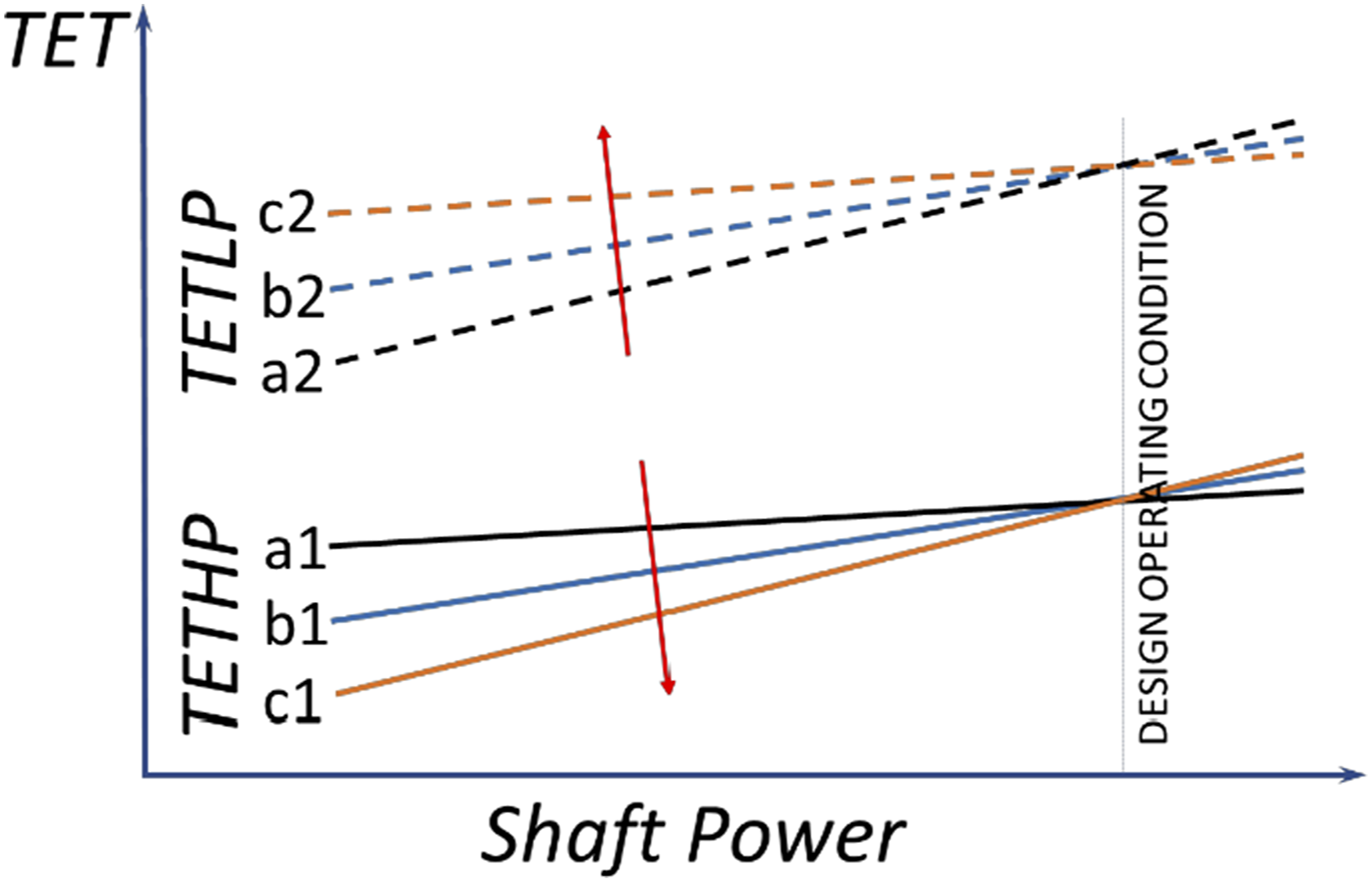
Control schedule 2:
– TETLP control
With this control schedule,
As TETHP and TETLP are closely coupled, the Control Schedules 1 and 2 are equivalent from performance perspective. Therefore, in this study only
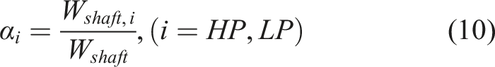
As the objective of having an inter-stage combustor to split the turbine into two sections is to make the thermal cycle of the gas turbine engine closer to Carnot cycle as shown in Figure 1(b), the expansion ratio of the turbine HP section should be lower than that of the turbine LP section as shown in Figure 1(c). If the expansion ratio of the turbine LP section is much higher than that of the turbine HP section, which is the case in this study, the turbine LP section would generate much more shaft power than that of the turbine HP section. As the gas turbine engine works in a wide range of ambient and operating conditions, it is desirable that the two turbine sections keep more or less the same relative distribution of workloads at all off-design operating conditions. Therefore, the turbine entry temperatures of the two turbine sections should change in a certain way to ensure such desire is satisfied, which would be beneficial to both the aerodynamic performance and the balanced creep life consumption of the two turbine sections. For that purpose, load coefficients to measure the share of the workload of the two turbine sections are introduced and defined by Eqs. (10) and (11)

In general, the power setting parameters
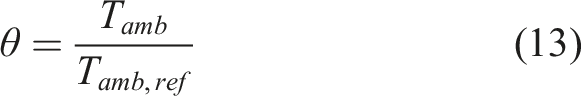
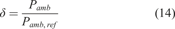
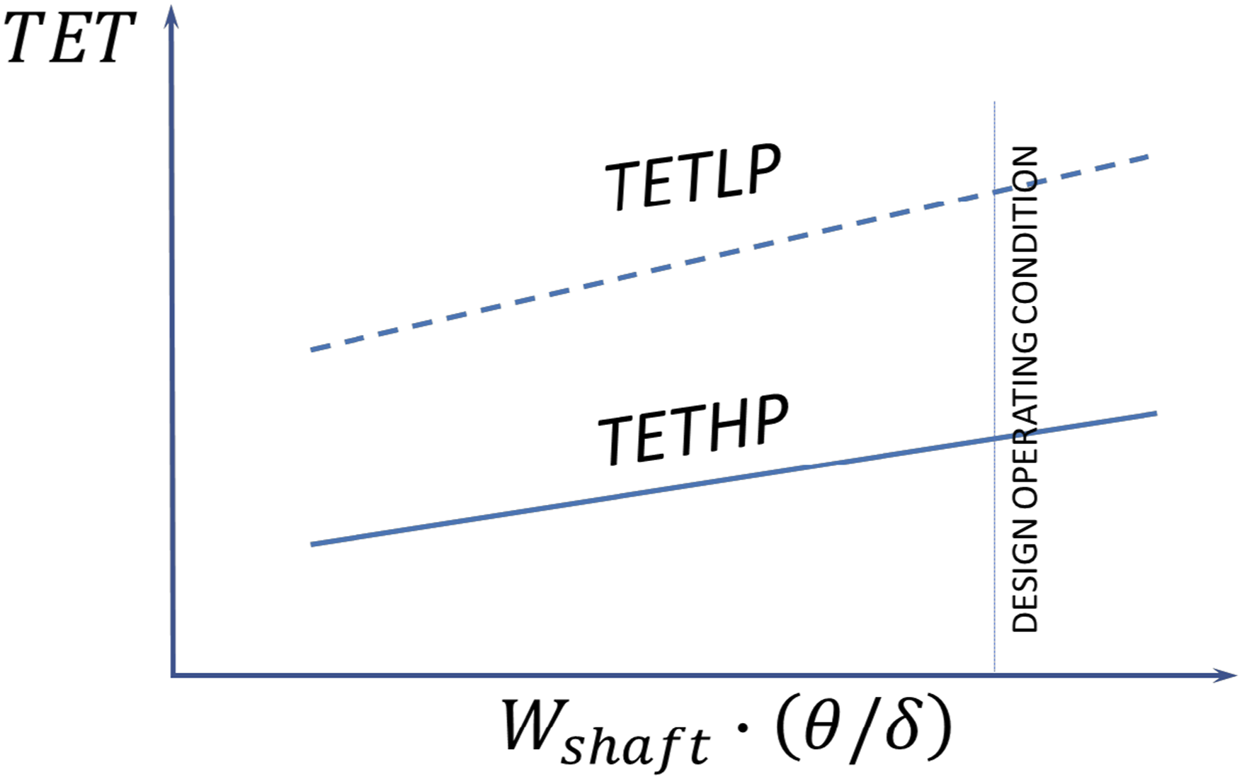
In addition, ambient conditions mainly represented by ambient pressure and temperature, determine the density of ambient air and have a significant impact on engine air flow rate and consequently shaft power output. To consider the impact of changing ambient conditions, TETHP may be controlled as a function of
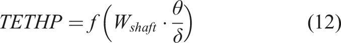
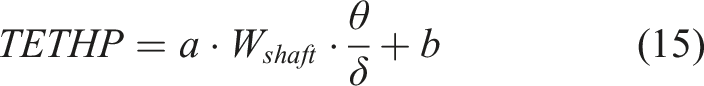
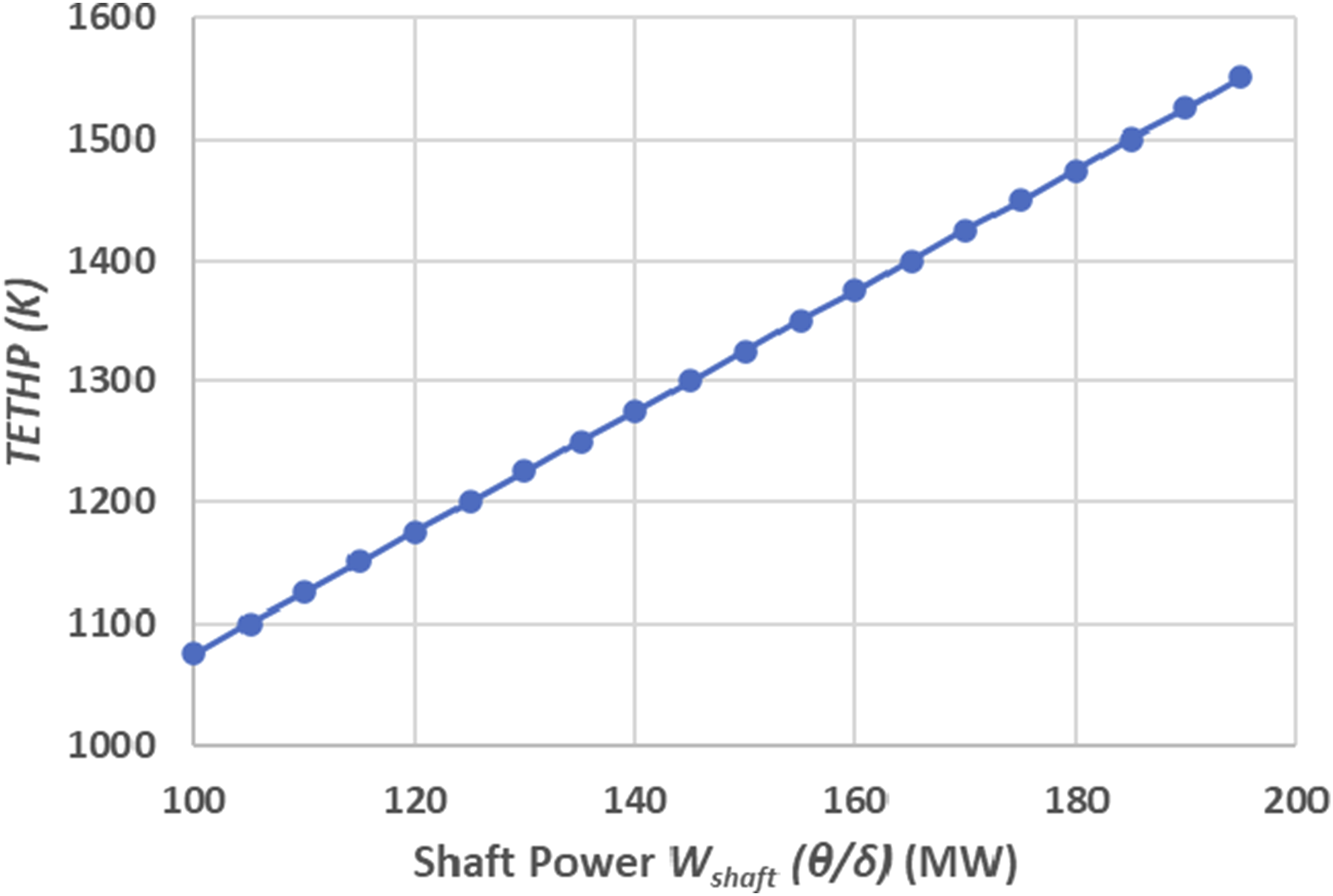
For each gas turbine engine, trials and errors may be conducted to find the best functional relationship between TETHP and Load coefficients versus corrected shaft power. TETHP - W_shaft∙(θ/δ) control schedule.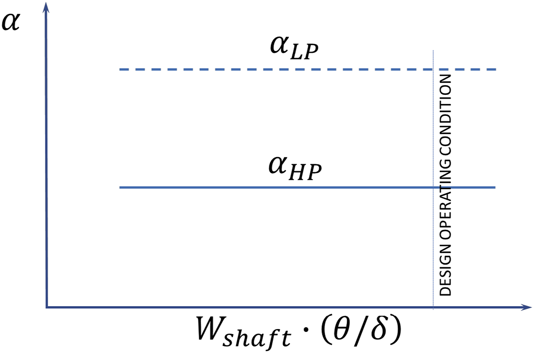
As gas turbine engines are nonlinear thermodynamic systems, such simplicity in designing the control schedule would benefit the implementation of the control schedule but the turbine load coefficients may be kept close to but not exactly constant at all off-design operating conditions.
Once Eq. (15) becomes available, the functional relationships between TETHP, TETLP and • • TETHP is the 2nd power setting parameter, and its value is determined by Eq. (15) or Figure 8. • The value of TETLP can be obtained from Figure 8 based on • The fuel flow rates to the main combustor Schematic engine control system.
Based on the suggested off-design performance control schedule, the following are some discussions for different scenario of ambient conditions for the engine to deliver required shaft power: • At a constant ambient condition where • At a constant demand of power output • At a constant demand of power output • In a situation where both ambient pressure and temperature change simultaneously, TETHP varies depending on the combined effect of ambient pressure and temperature on the corrected shaft power. In other words, TETHP increases when
Modern single shaft gas turbines have variable IGV to ensure high TET and therefore high thermal efficiency at part load operating conditions, and so is this model engine. In other words, the compressor IGV of the model engine is set to close when the engine power output decreases. The control schedule of the IGV angle used in this study is shown in Eq. (16) where the IGV angle is a function of the referred relative total shaft power of the two turbine sections. Such a IGV control schedule may be chosen based on the compressor map and desired engine performance to ensure that the compressor air flow rate is reduced by closing the IGV when engine shaft power output reduces.

Demonstration of applications
The introduced engine off-design performance simulation method and performance control schedule have been implemented into Cranfield gas turbine performance and gas path diagnostics software, Pythia 21 and applied to a model single-shaft industrial gas turbine engines with sequential combustors similar to GT24/26 to demonstrate the application of the methods.
Model engine
A performance model for the model sequential combustion gas turbine engine was set up for the study. The model engine has one compressor, one main combustor followed by two turbine sections on the same shaft with an inter-stage reheat combustor in between. The configuration of the model engine is shown in Figure 3 and its performance specification at standard sea level static ISA condition is shown in Table 1. It is assumed that • • The shaft rotational speed is kept constant at off-design operating conditions assuming that the gas turbine engine is used for electricity generation and connected to a national grid. • The shaft power output can increase, decrease, or keep constant depending on external power demands. • The two turbines are air cooled with 10% air extracted from the exit of the compressor for the cooling of the turbine HP section and 7% air extracted from the 50% pressure ratio position of the compressor for the cooling of the turbine LP section. Performance specification of model engine at standard sea level static ISA condition.
Off-design performance simulation and control schedule
Selected matching variables of model engine.
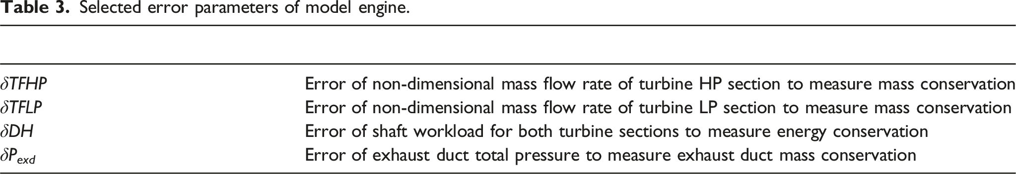
Selected error parameters of model engine.
Newton Raphson iteration method described in Section “Gas turbine off-design performance simulation approach” is used to obtain a converged solution when the model engine moves from one off-design operating point to another.
The off-design performance control schedule presented in Section “Off-design performance control strategy” is used to set up a functional relationship between the two power setting parameters, Off-design performance control schedule.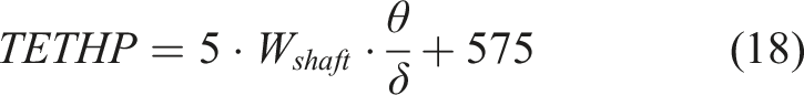
The IGV angle is controlled by a control schedule shown in Figure 11 that take a special form of Eq. (16) where the IGV angle keeps 0 when the referred relative shaft power IGV control schedule.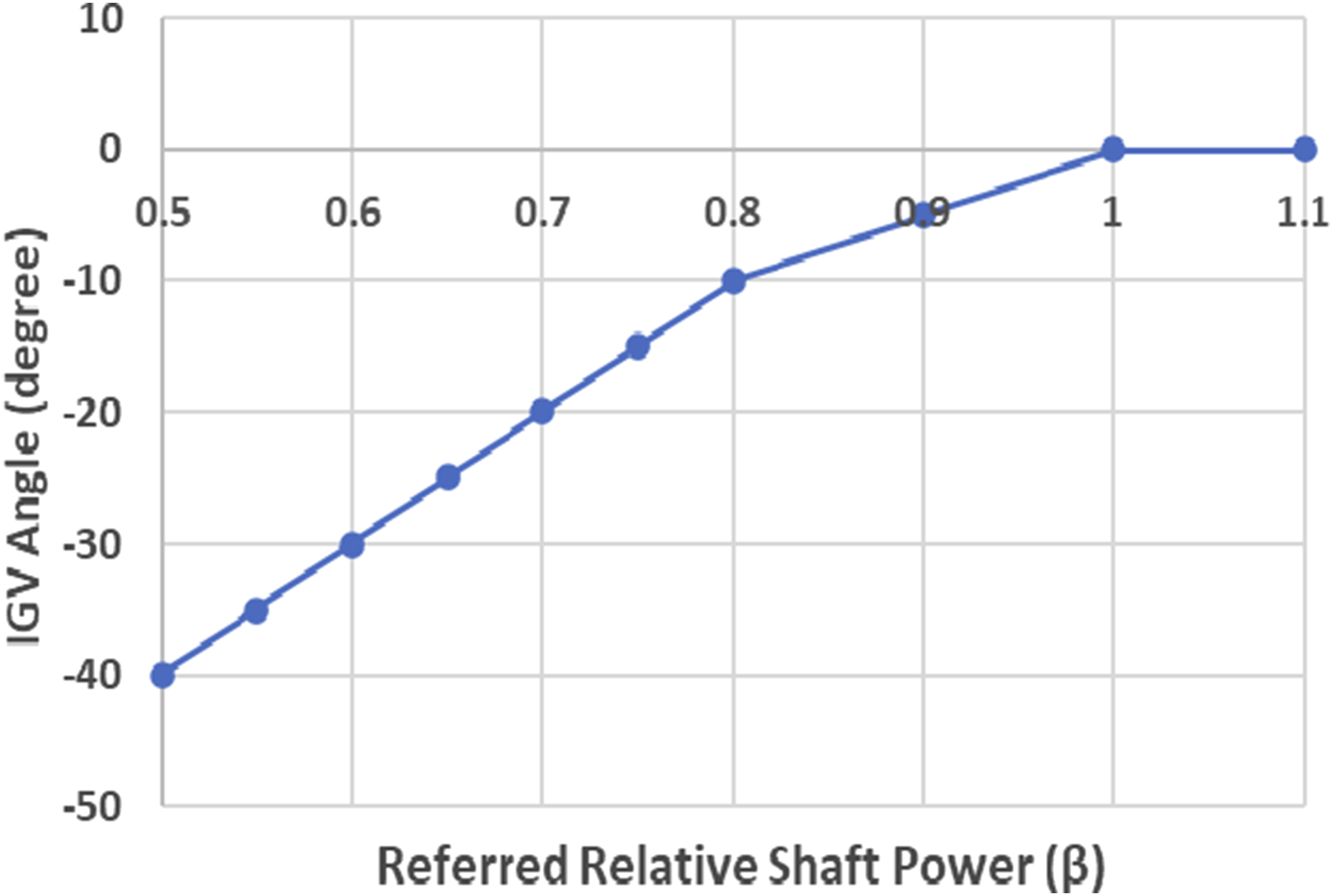
To assess if the proposed control schedules could satisfactorily control the turbine load coefficients at constant values at different off-design operating conditions, the following four test cases are conducted.
Test case 1: Impact of part-load operations
In this test case, it is assumed that the ambient condition is constant and at the standard sea level static ISA condition where
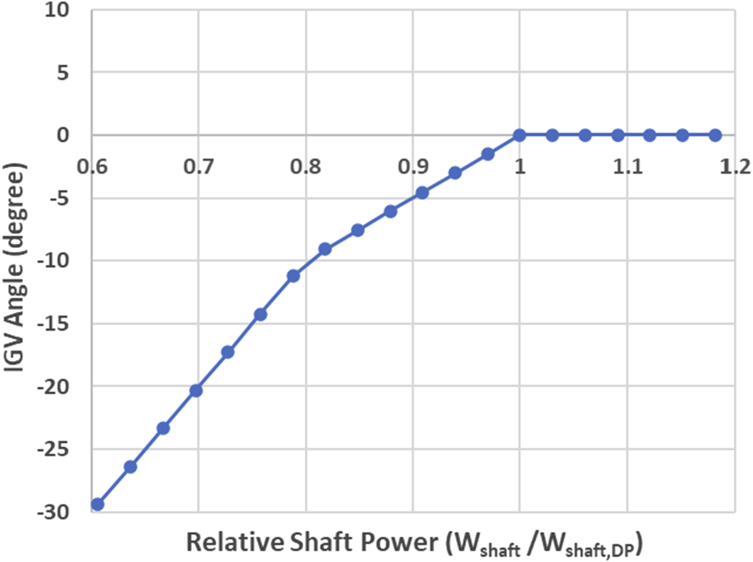
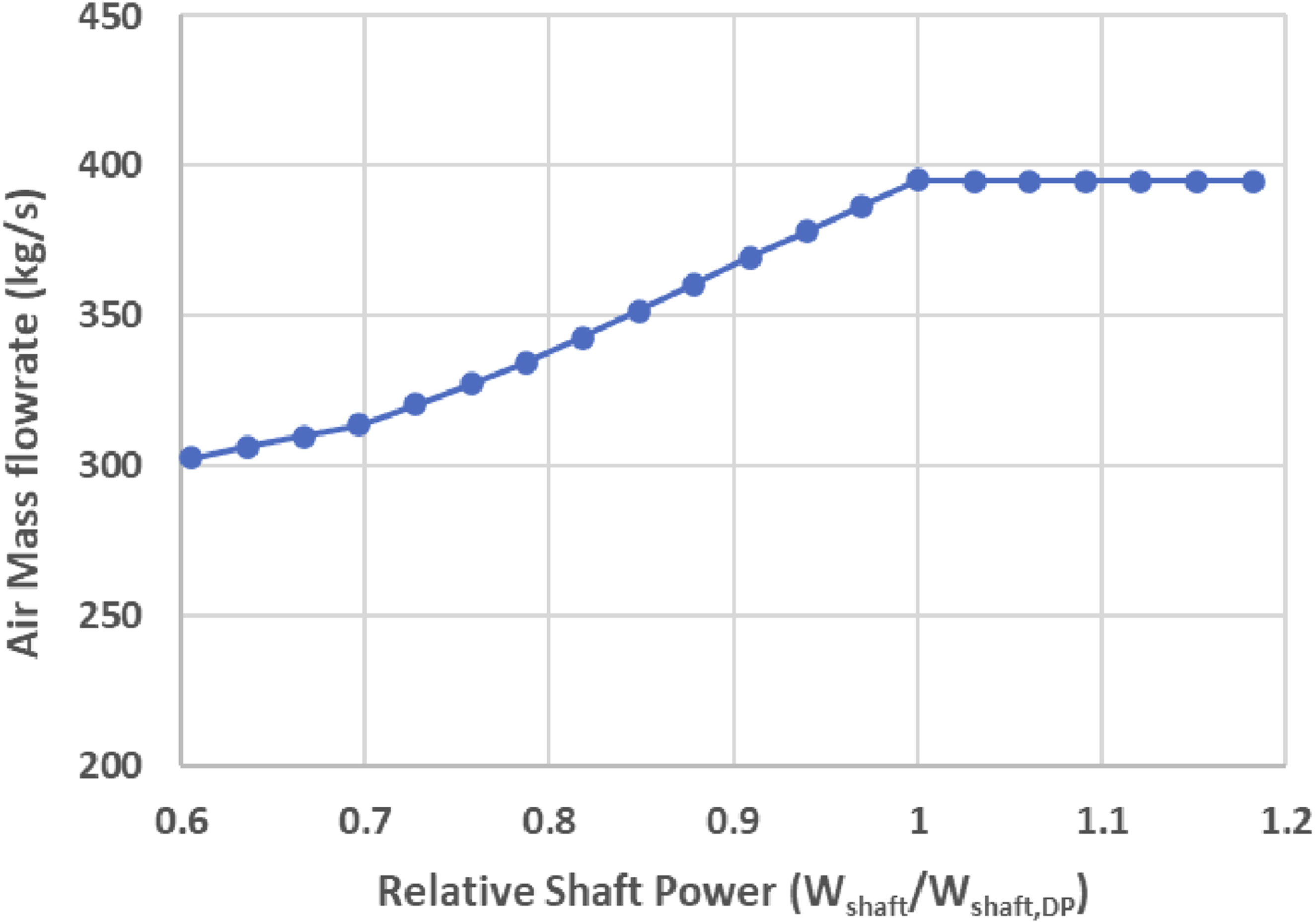
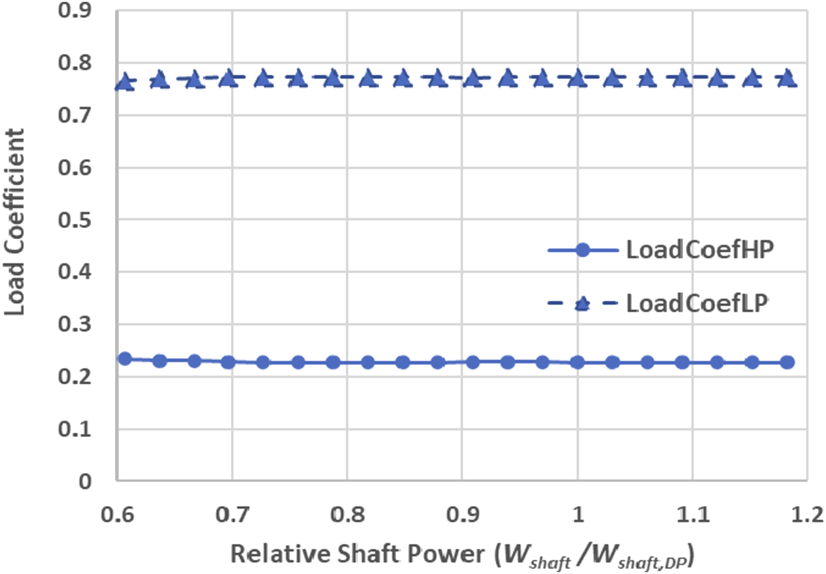
When the model engine delivers shaft power from 195 MW to 100 MW, the performance of the engine is simulated with its performance model following the off-design performance control schedule shown in Figure 10 and the IGV control schedule shown in Figure 11, and the results are shown in Figures 12–16. It can be seen in Figure 12 that TETLP reduces almost in parallel with TETHP. The IGV angle variation shown in Figure 13 results in the engine air flow rate only reducing from 395 kg/s at and above design power to about 300 kg/s at 100 MW as shown in Figure 14. Consequently, the load coefficient TETs vs relative shaft power (Tamb = 15°C & Pamb = 1 atm). IGV Angle versus relative shaft power (Tamb = 15°C & Pamb = 1 atm). Air flow rate versus relative shaft power (Tamb = 15°C & Pamb = 1 atm). Load coefficients versus relative shaft power (Tamb = 15°C & Pamb = 1 atm). Thermal efficiency versus relative shaft power (Tamb = 15°C & Pamb = 1 atm).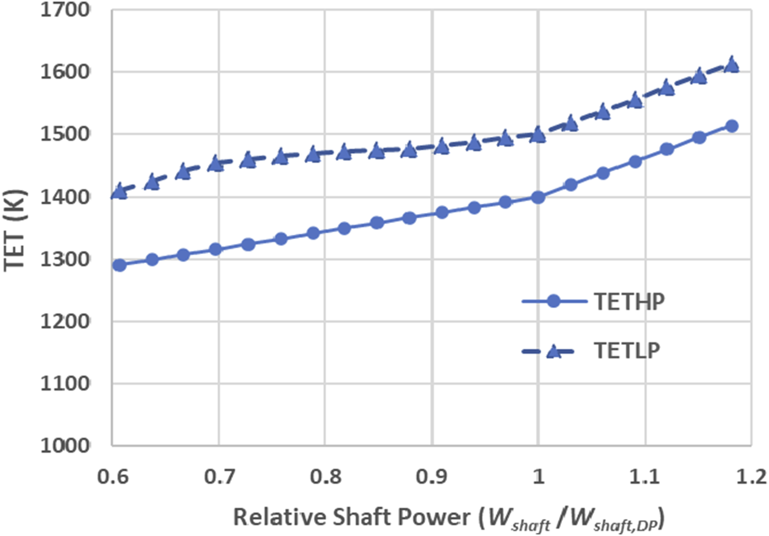
Test case 2: Impact of ambient temperature
This test case is used to assess the impact of changing ambient temperature on the performance of the model gas turbine at different power levels while keeping the ambient pressure constant at 1 atm. Two levels of power output are considered in the analysis, one at the design load of 165 MW and the other at a part load of 120 MW.
To keep the power output constant, both TETHP and TETLP have to increase when ambient temperature increases resulting in the drop of ambient air density, and vice versa. Figure 17 shows how TETHP of the model engine vary with the ambient temperature between −25°C and 35°C based on the control schedule shown in Figure 10 and how TETLP responds accordingly. It can be seen in Figure 17 that TETHP and TETLP cross over when ambient temperature decreases. At the part load of 120 MW, both TETHP and TETLP become lower than those at the design power of 165 MW and vary with ambient temperature in a similar way as those at the design power. The gap of TETHP between the two power levels is bigger than that of TETLP, with the gap of around 70K for TETHP and around 40K for TETLP. TETs versus ambient temperature (Pamb = 1 atm).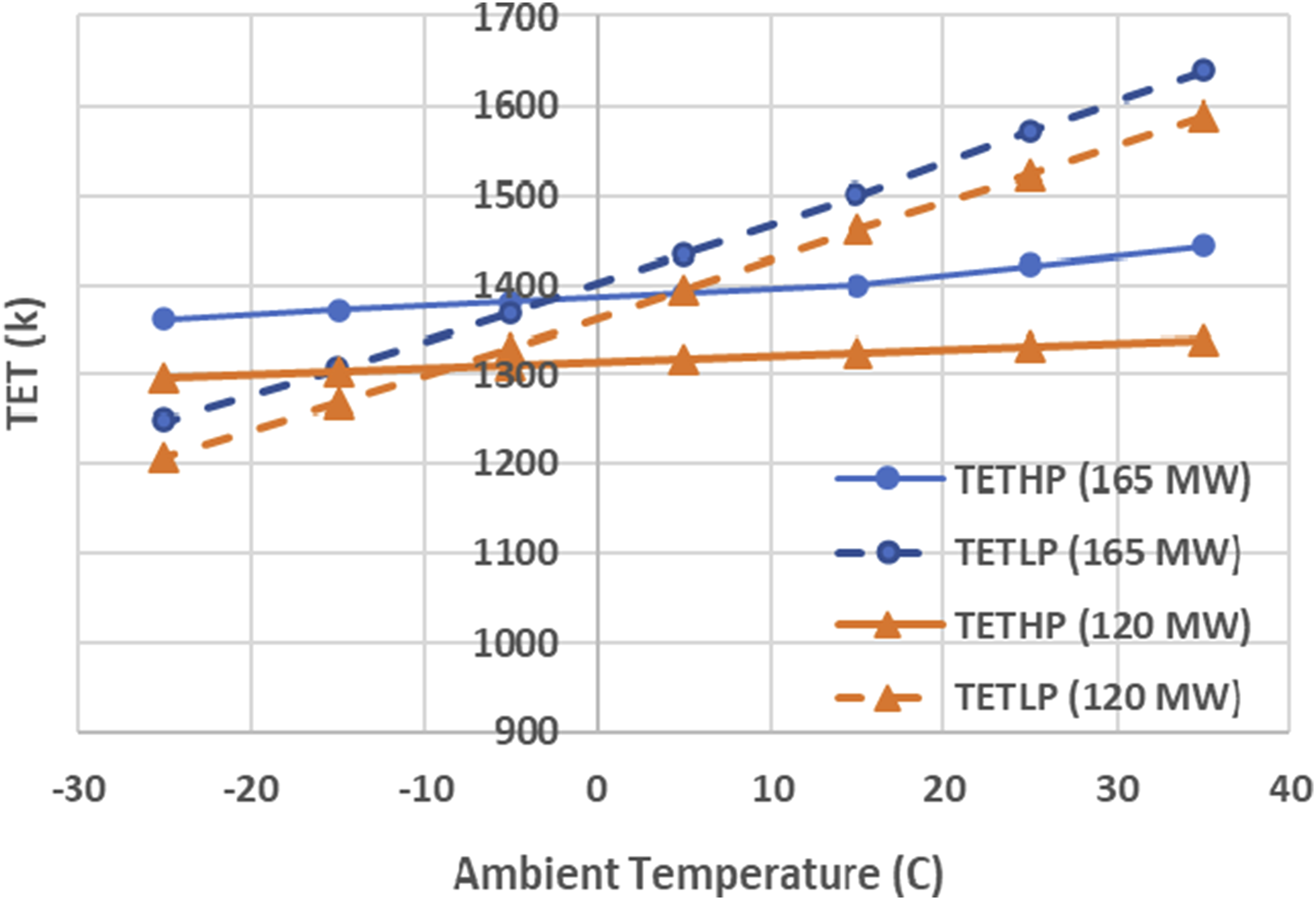
As shown in Figure 18, at high power output of 165 MW the IGV angle is kept 0° at ambient temperature below 15°C and start to decrease when the ambient temperature is above 15°C. At low power output of 120 MW, the IGV angle is kept decreasing when the ambient temperature increases. IGV angle versus ambient temperature (Pamb = 1 atm).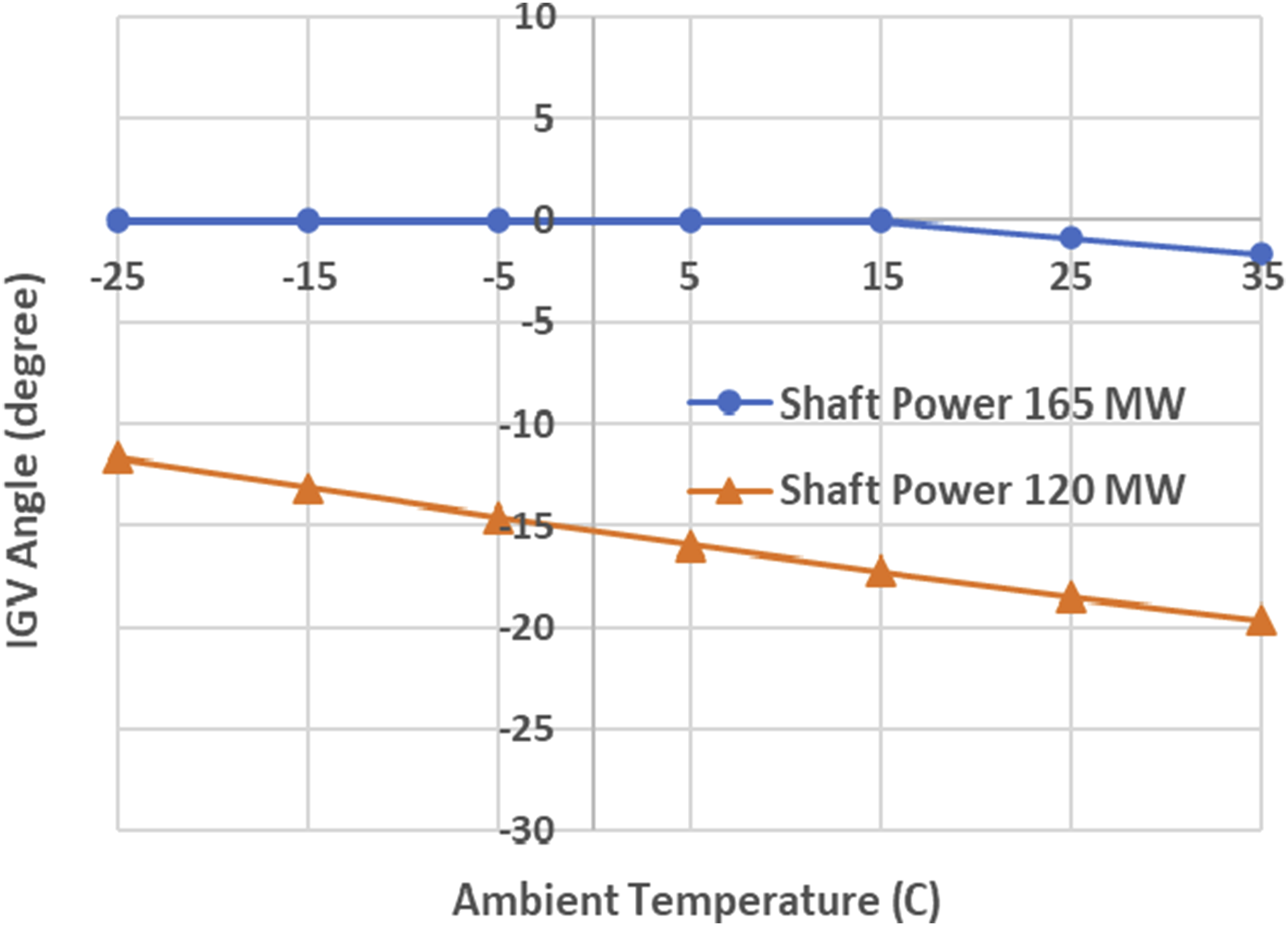
The turbine load coefficients Load coefficients varying with ambient temperature (Pamb = 1 atm).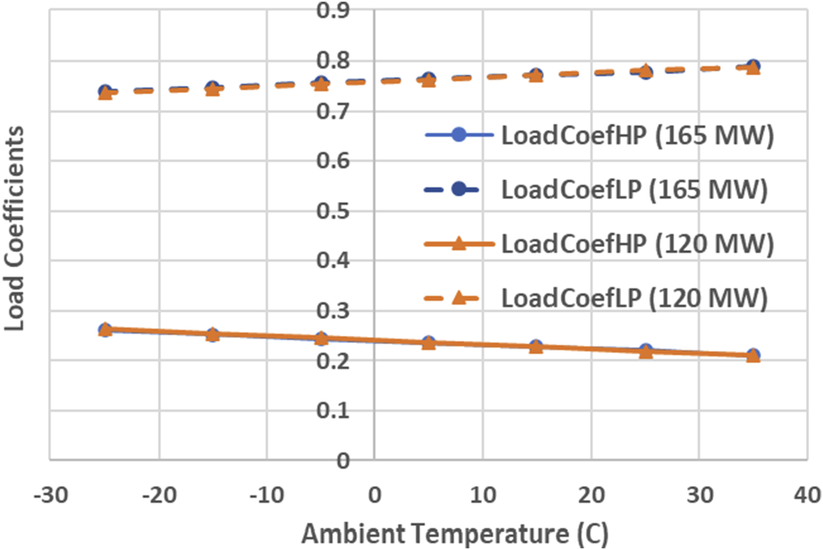
As the result of the chosen TET and IGV angle controls, the thermal efficiency of the engine has modest drops from 42.8% to 38.5% at 165 MW and from 38.7% to 35.9% at 120 MW when ambient temperature increases from −25°C to 35°C as shown in Figure 20.
Test case 3: Impact of ambient pressure
This test case is used to assess the impact of changing ambient pressure on the performance of the model gas turbine at different power levels while keeping the ambient temperature constant at 288.15 K. Two levels of power output are considered, one at the full load of 165 MW and the other at a part load of 120 MW.
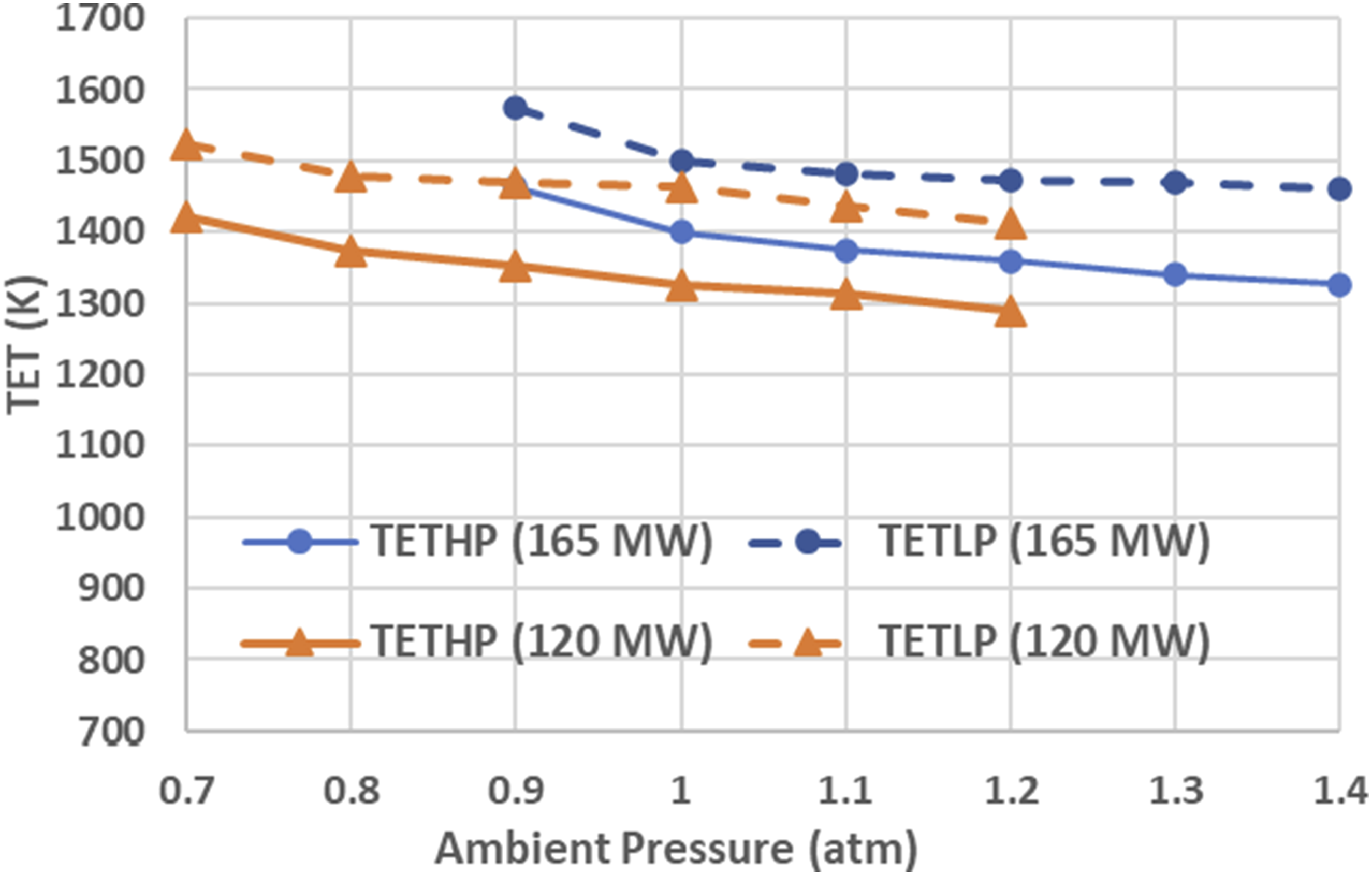
To keep the power output constant, TETHP and TETLP have to increase when ambient pressure drops, and vice versa. Figure 21 shows the variation of TETHP and TETLP corresponding to the ambient pressure variation between 0.7 and 1.4 atm where TETHP and TETLP changes almost in parallel. At the part load of 120 MW, TETHP and TETLP become lower than those at the design power and they vary with ambient pressure in a similar way as those at design power of 165 MW. It can also be seen in the figure that the gaps between TETHP and TETLP becomes slightly smaller when ambient pressure drops, changing from 136K at ambient pressure of 1.2 atm to 100K at ambient pressure of 0.9 atm at the design power of 165 MW, and from 120K at ambient pressure of 1.2 atm to 100K at ambient pressure of 0.7 atm at the part load of 120 MW. Thermal efficiency versus ambient temperature. TET varying with ambient pressure (Tamb = 288.15 K).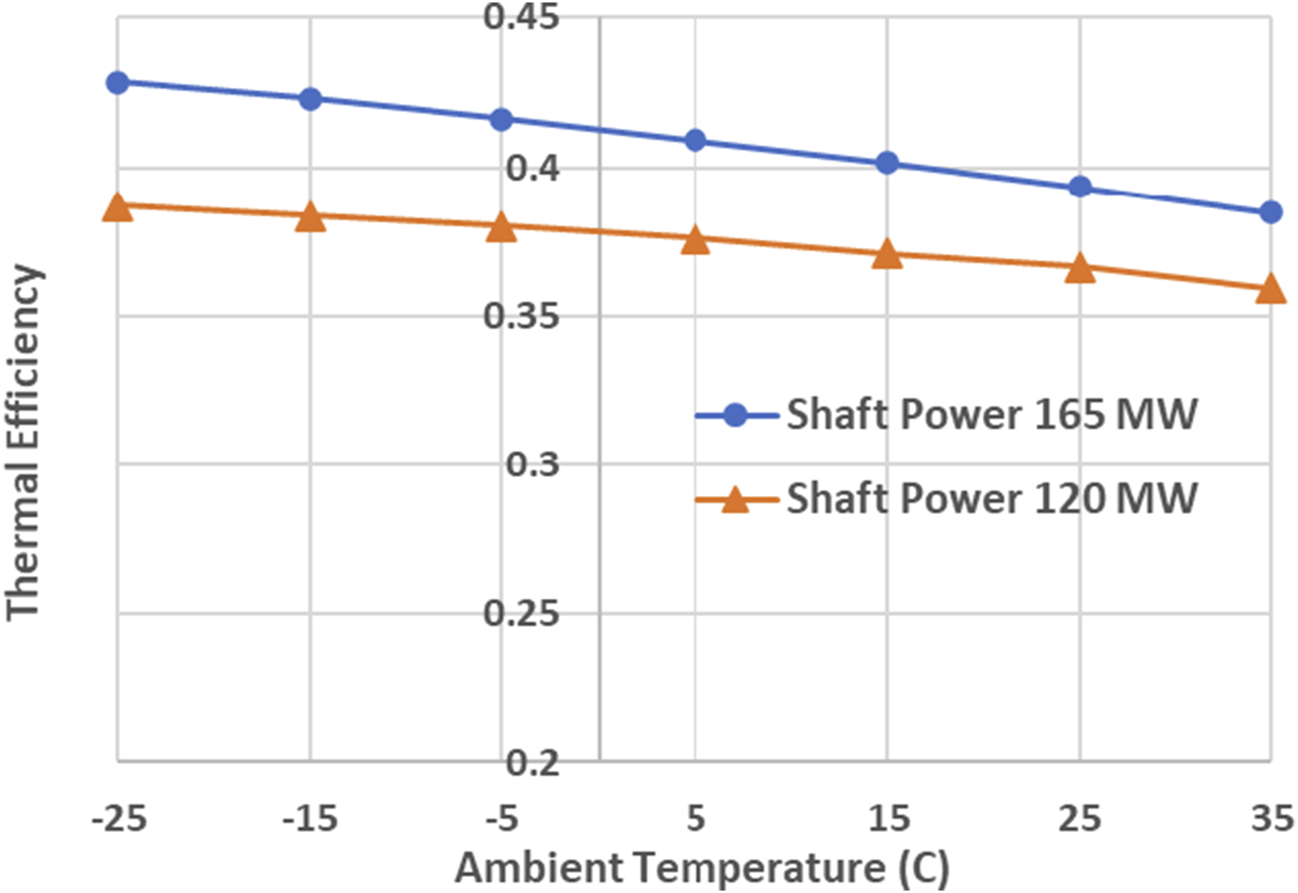
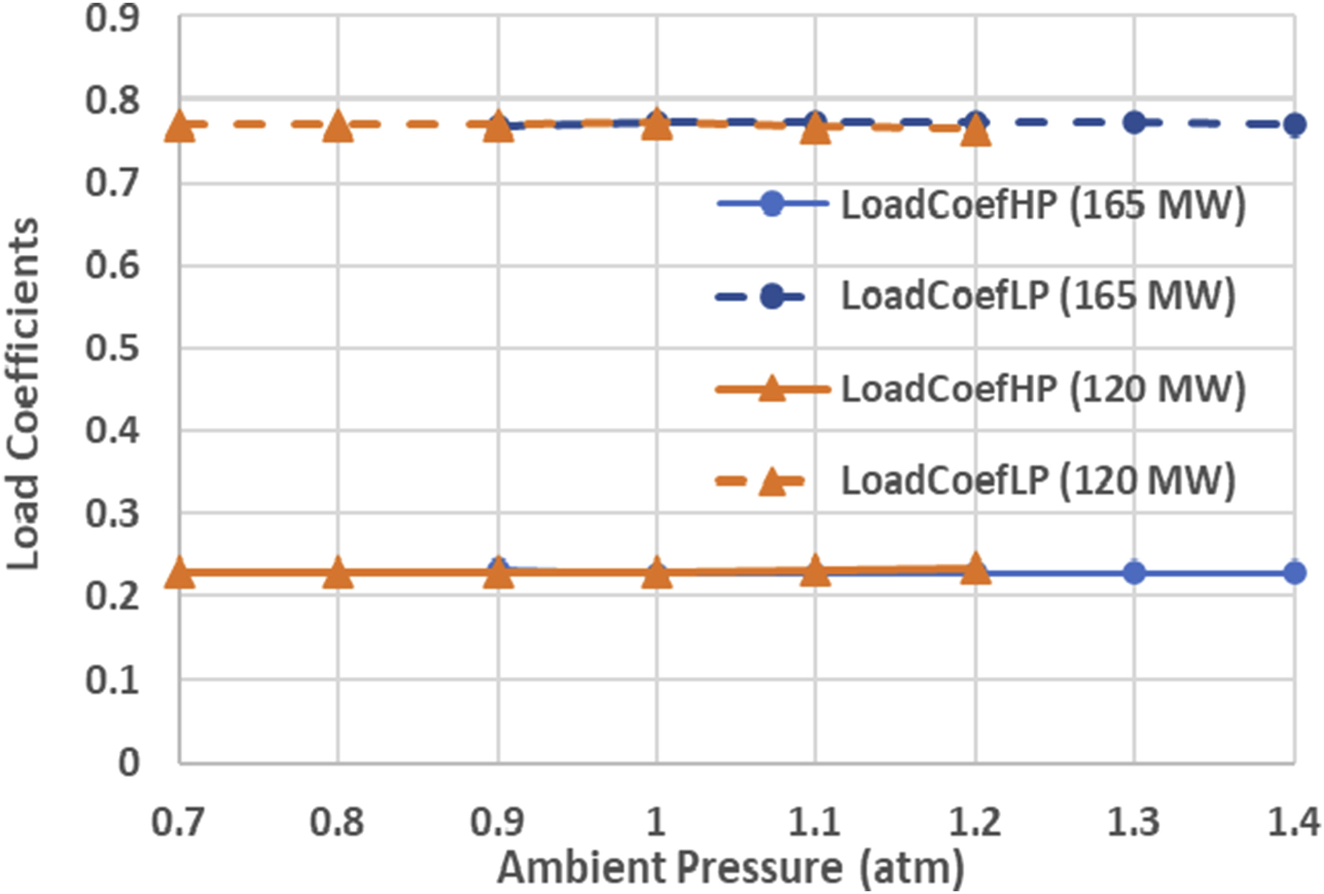
The IGV angle decreases when the ambient pressure increases as shown in Figure 22 except in the situation where the IGV is kept 0° when the ambient pressure is below 1 atm at 165 MW. Consequently, the turbine load coefficients α1 and α2 are kept almost constant, with α1 at around 0.23 and with α2 at around 0.77, with an absolute variation of around 0.004 as shown in Figure 23. Due to the significant difference in the absolute values of the baseline load coefficients between the two turbine sections, the relative variation of the load coefficient is 1.8% for the turbine HP section and is 0.5% for the turbine LP section. IGV angle versus ambient pressure. Load coefficient varying with ambient pressure (Tamb = 288.15 K).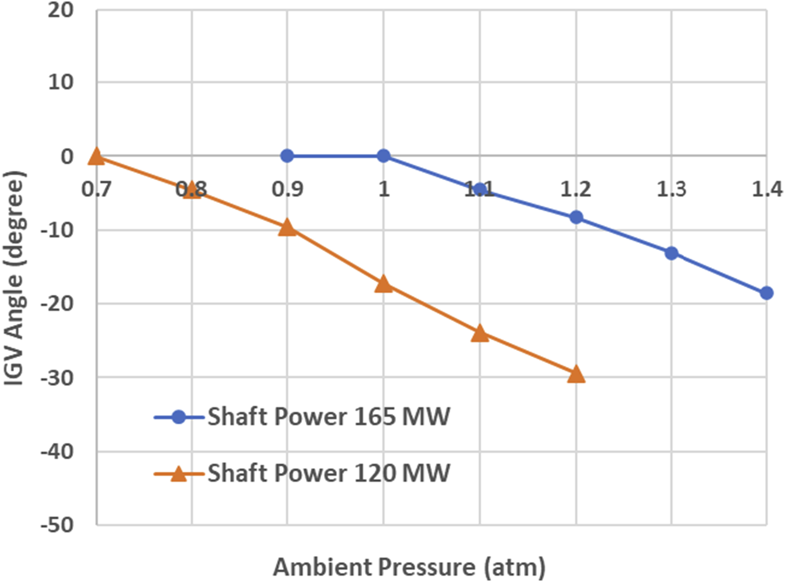
The thermal efficiency of the engine is kept at high level as shown in Figure 24, with a modest drop from 40.7% to 36.9% at 165 MW when the ambient pressure increases from 0.9 to 1.4 atm, and from 40.4% to 34.9% at 120 MW when the ambient pressure increases from 0.7 to 1.2 atm. Thermal efficiency versus ambient pressure.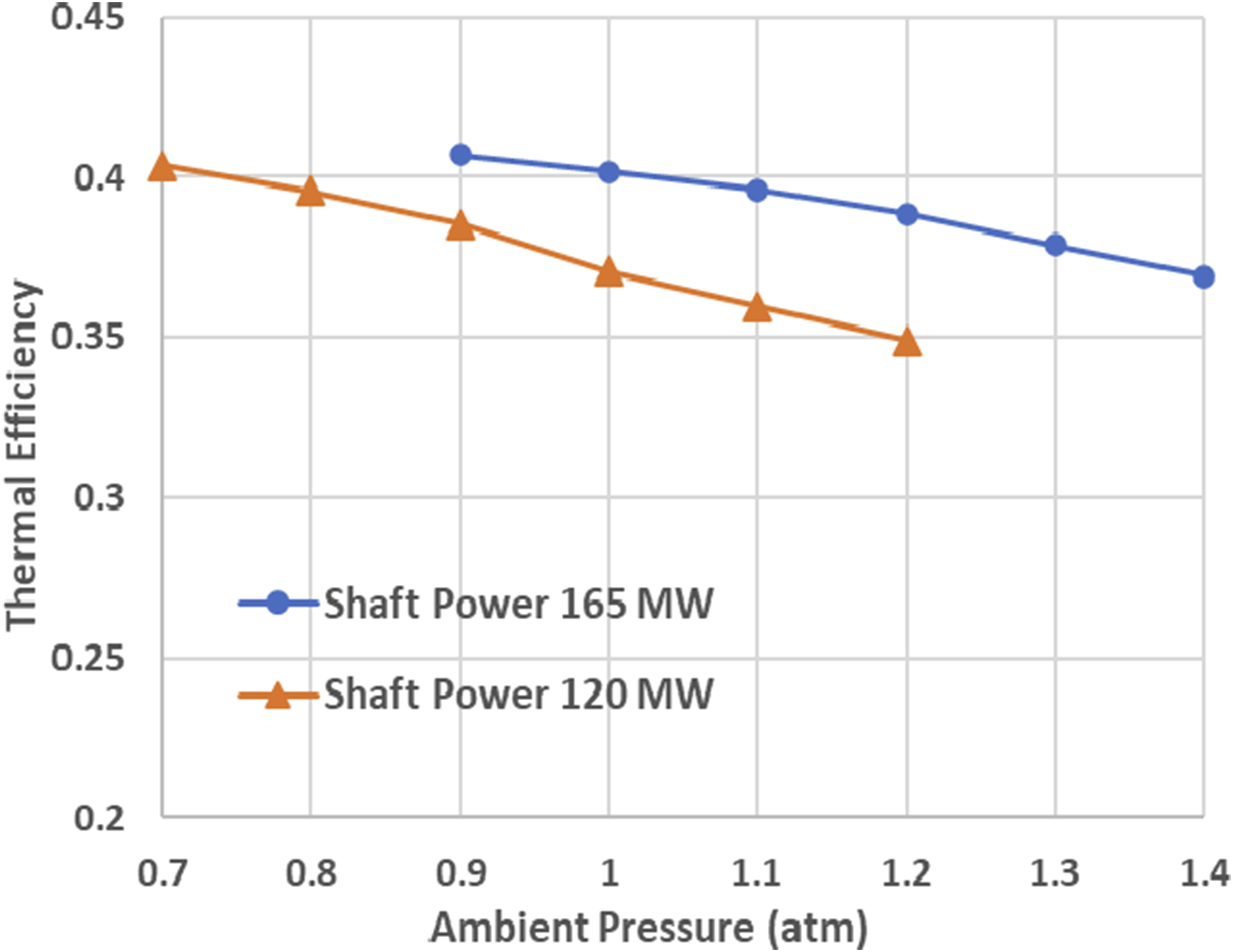
Test case 4: Impact of both ambient pressure and temperature
Depending on geographical locations and seasons, ambient pressure and temperature may vary significantly. To demonstrate that the proposed control schedule works for industrial gas turbine engines working at extreme ambient conditions, the ambient condition at La Paz, the capital city of Bolivia is chosen for the analysis. It is the highest city in the world located at the altitude of 3650 m above sea level and the average yearly temperature changes between −3°C and 17°C and the average ambient pressure is around 0.7 atm.
In this case study, it is assumed that the ambient temperature is 5°C and the ambient pressure is 0.7 atm. Due to the high altitude where the ambient pressure and air density are low, the model engine may deliver much lower shaft power than at sea level static ISA condition. Therefore, it is assumed that the model engine is run from 125 MW to 75 MW (75.8% to 45.5% of power at design condition) and TETHP is controlled following the control schedule shown in Figure 10.
Figure 25 shows how TETHP vary with the shaft power output and how TETLP responds accordingly. It can be seen in the figure that TETHP changes almost linearly with the shaft power while TETLP changes almost in parallel with TETHP. In other words, the gap between TETHP and TETLP increases from about 30K to about 80K when the shaft power changes from 125 MW to 75 MW (75.8% to 45.5% of design power). IGV angle is kept 0° from 125 to 115 MW (75.8% to 69.7% of design power) and then gradually decreases to −24° when the shaft power drops to 75 MW (45.5% of design power), as shown in Figure 26. TETs varying with relative shaft power (Tamb = 5°C & Pamb = 0.7 atm). IGV angle versus relative shaft power.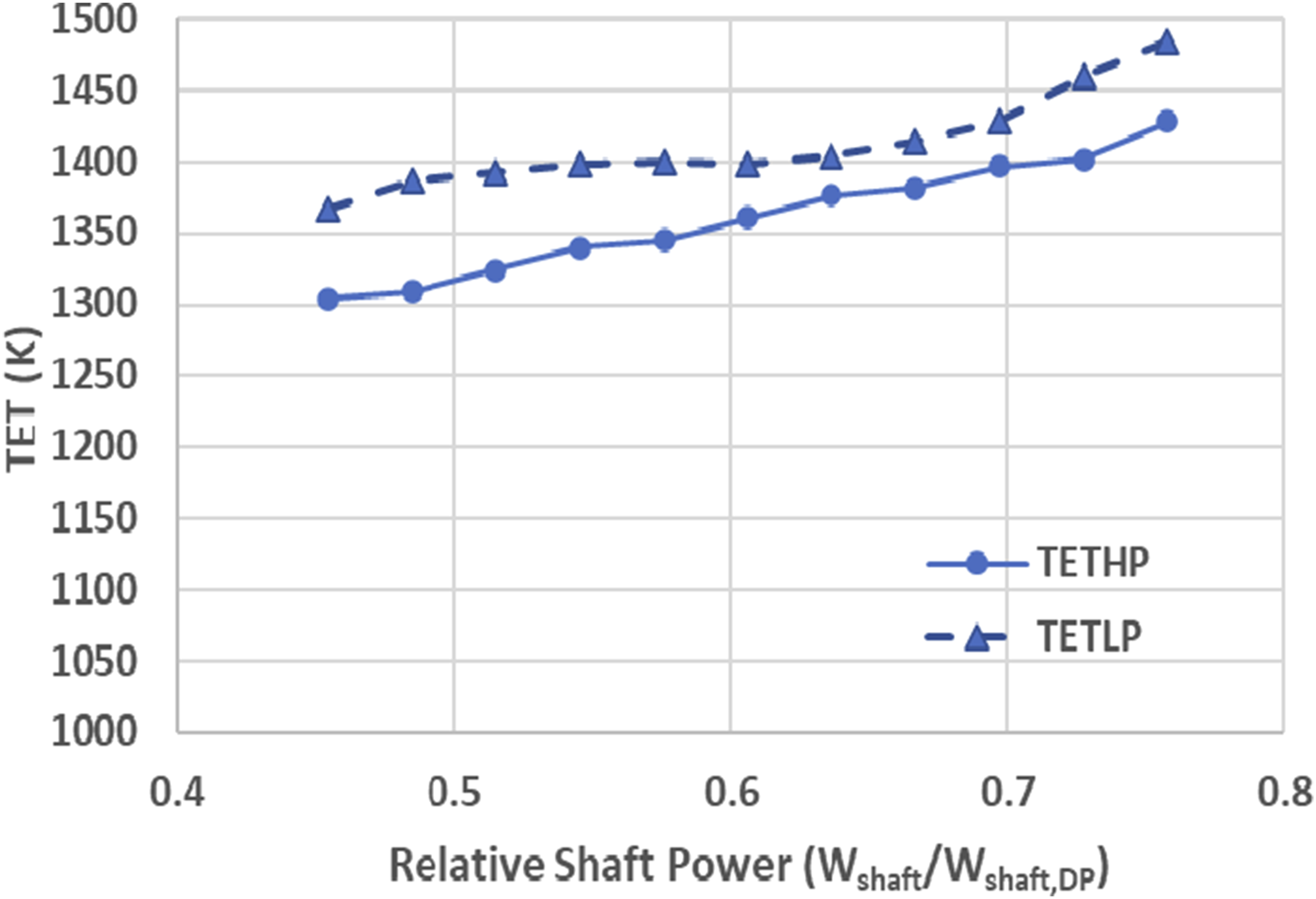
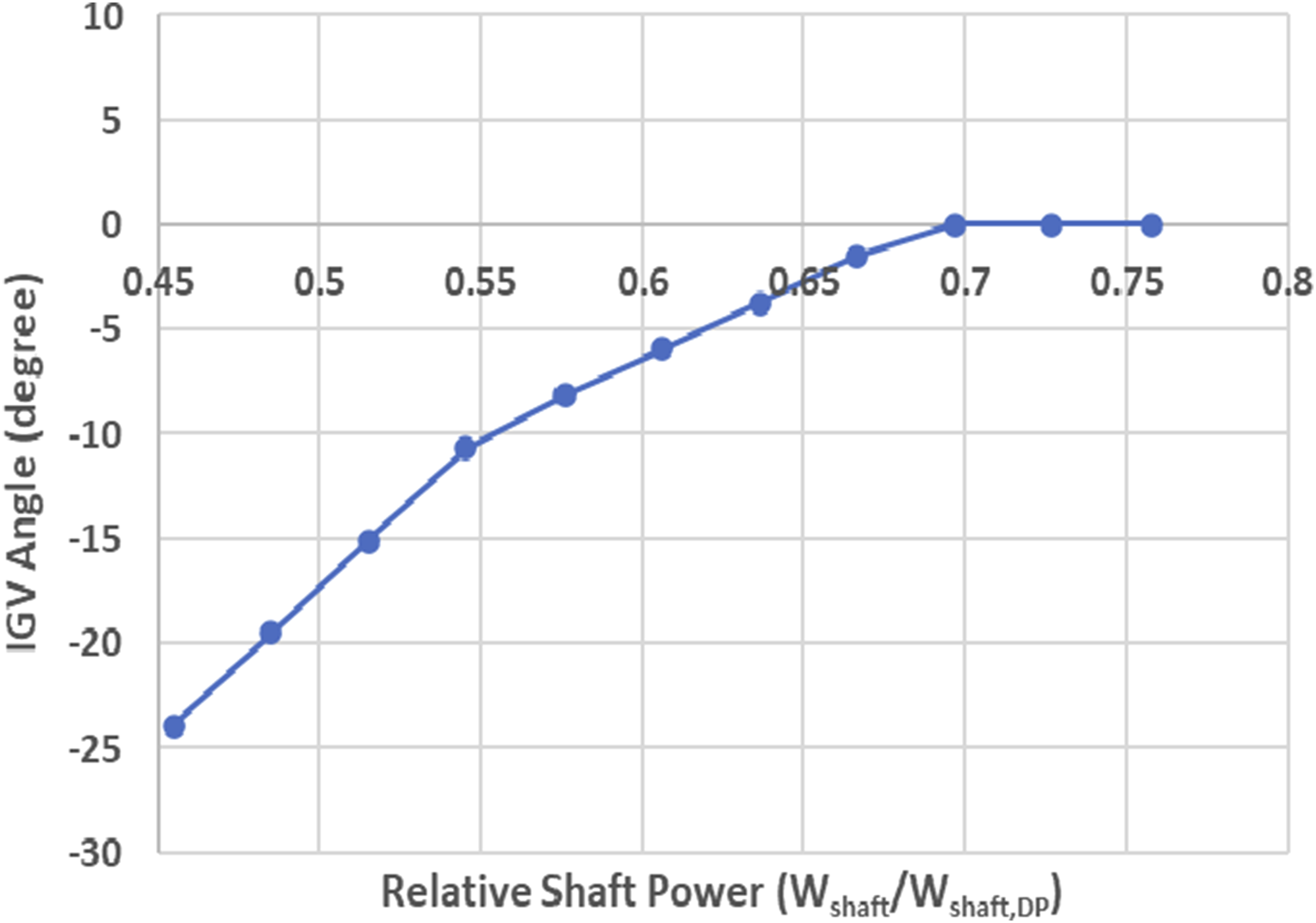
Figure 27 shows the load coefficients Load coefficients varying with relative shaft power (Tamb = 5°C & Pamb = 0.7 atm).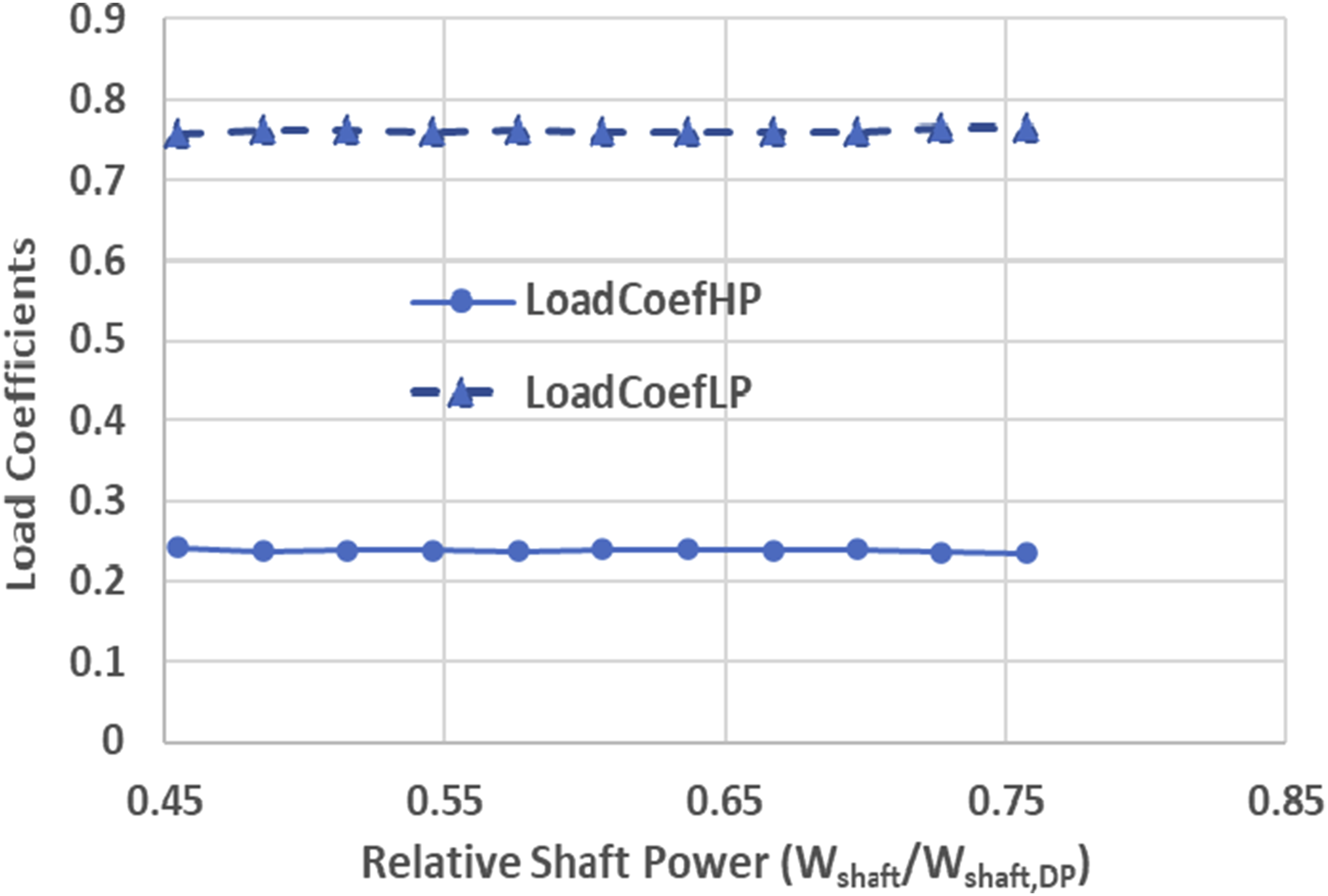
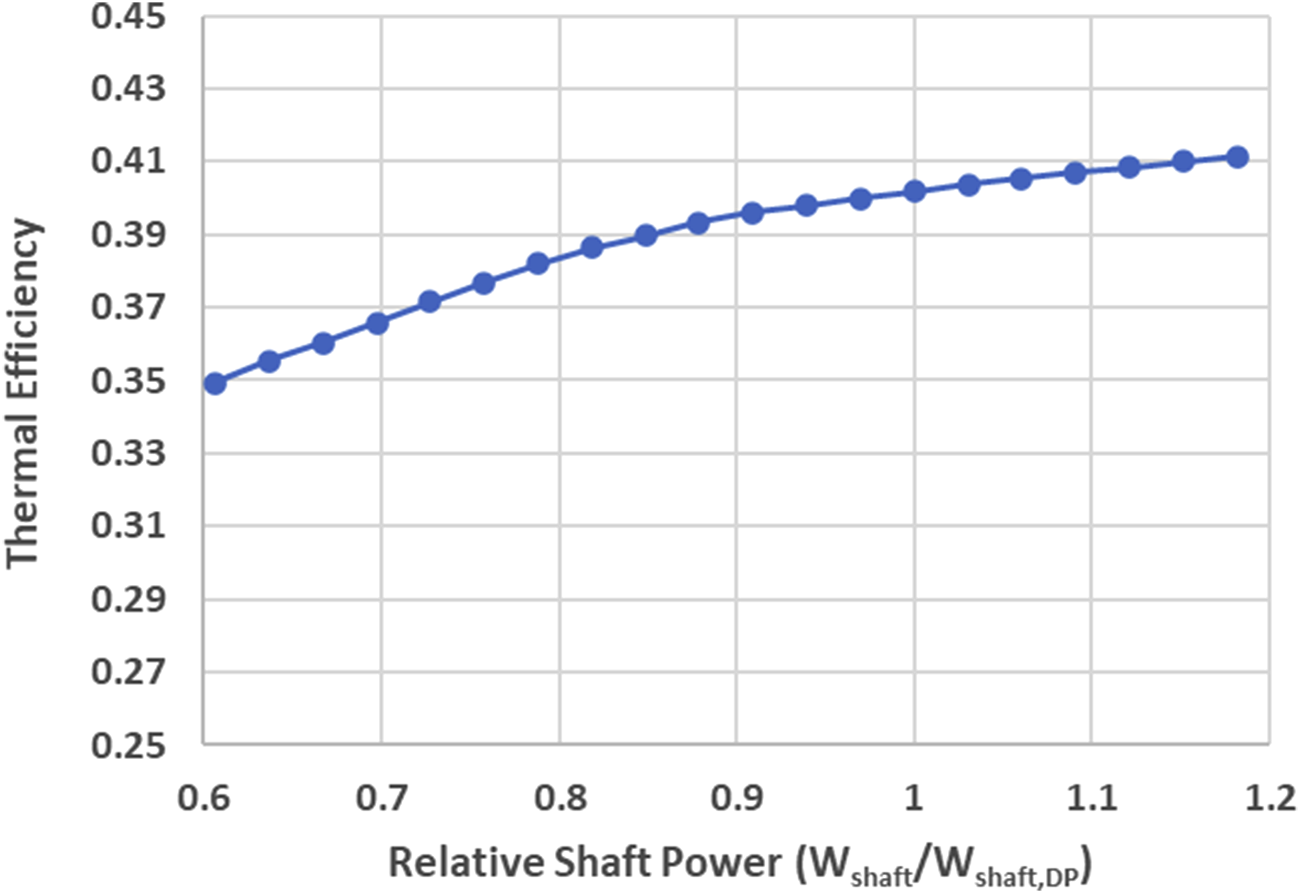
The thermal efficiency of the engine is kept at high level with a modest decrease from 41.3% at the shaft power of 125 MW (75.8% of design power) to 36.2% at the shaft power of 75 MW (45.5% of design power) as shown in Figure 28. Thermal efficiency versus relative shaft power.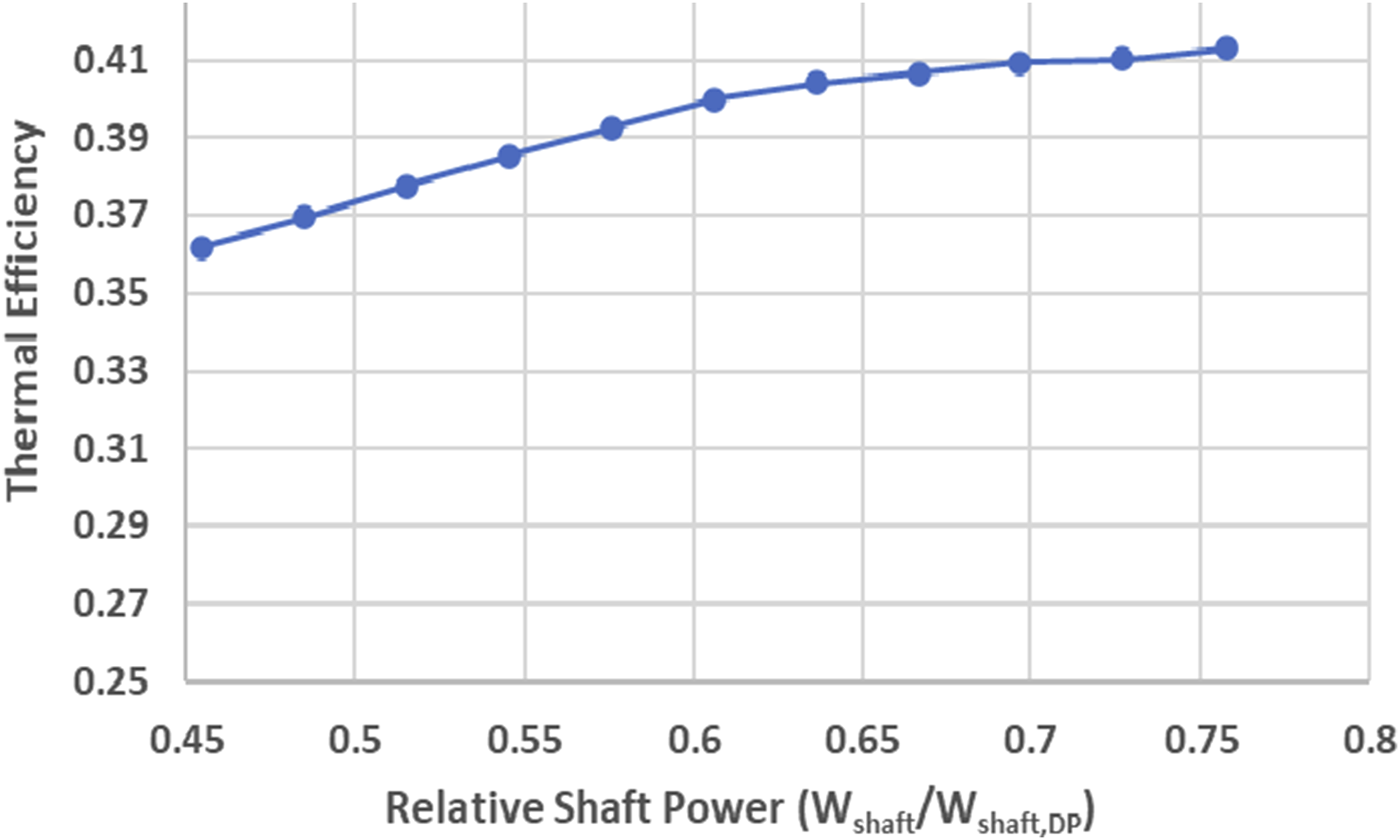
Conclusions
The paper introduces a novel off-design performance simulation method for single-shaft industrial gas turbine engines with sequential combustors where two power setting parameters are considered, one is the shaft power output and the other is the turbine entry temperature of the turbine HP section. Correspondingly, a novel off-design performance control schedule is proposed where the entry temperature of the turbine HP section is set as a linear function of the corrected shaft power output aiming to keep the load distribution between the two turbine sections reasonably constant. A compressor IGV control schedule where the IGV angle is a function of referred relative shaft power is also introduced to reduce compressor air flow rate and keep engine thermal efficiency high at part load operating conditions. Such an off-design performance control schedule is simple, easy for implementation and is able to ensure that the gas turbine engines can meet external power demands, control the engine off-design performance effectively, keep the workload distribution between the two turbine sections reasonably constant and maintain high thermal efficiency at all off-design operating conditions.
The introduced performance simulation method and the off-design control schedule have been applied to a model industrial gas turbine engine with sequential combustors operating at different ambient and off-design operation conditions to demonstrate the effectiveness of the methods. The simulation results in the four test cases show that the workload distribution between the two turbine sections can be kept reasonably constant at different part-load and ambient conditions. The ambient temperature has more impact on the workload distribution between the two turbine sections than the ambient pressure within the scope of discussions. In other words, the variation of around 0.052 of the load coefficient would happen due to ambient temperature variation between −25°C and 35°C, compared to the variation of around 0.004 of the load coefficient due to ambient pressure variation between 0.7 atm and 1.2 atm. Consequently, the variation of ambient temperature could result in 23.6% relative variation of the load coefficient in the turbine HP section and 7.0% in the turbine LP section as the baseline value of the load coefficient of the turbine HP section (0.2278) is much lower than that of the turbine LP section (0.7722).
Footnotes
Declaration of conflicting interests
The author(s) declared no potential conflicts of interest with respect to the research, authorship, and/or publication of this article.
Funding
The author(s) disclosed receipt of the following financial support for the research, authorship, and/or publication of this article: The work was self-funded by Cranfield University.