
Abstract
Taylor Spatial Frame (TSF) is a type of hexapod external ring fixation system. TSF rings are supplied as half rings, whole full rings and two third rings in different sizes. In this work, these components as well as bolted full rings made of two half rings were tested in compression in two or three directions. Tests were simulated by Finite Element (FE) method using 3D solid elements, which were validated against the experimental results. Load-deflection curves and values for stiffness and ultimate loads are presented for each case from both tests and FE analyses. Load-stiffness curves are also presented for each test. The followings were demonstrated by the results: (1) a significant difference between bolted and whole full rings in their respective stiffness behaviour, the clear advantage being with the whole full rings, (2) a variation in stiffness of bolted rings when loaded across their different diameters, (3) a potential problem in the TSF rings: having the same cross section and thickness, smaller rings are stronger than larger ones, whereas in fact the larger ones ought to be stronger due to patient’s weight and that (4) the lowest stiffness was exhibited when a 2/3 ring was loaded parallel to the line joining its open ends.
Keywords
Introduction
Introduced in 2002, Taylor Spatial Frame (TSF) was the first of hexapod ring fixation systems. 1 External fixators are frames to which bone or bone fragments are fixated using transosseous elements such as pins or wires, 2 as in Figure 1. Circular or ring external fixation devices were originally created in 1950s by G. A. Ilizarov. In such fixators, the frame consists of circular elements (such as rings, half rings or the like) which support the transosseous elements and are connected via a number of interconnecting elements such as rods, struts and hinges. Ring fixation systems are truly modular and there exists a variety of elements to connect the rings with. The chosen elements should permit the dynamics necessary for the specific treatment process – for example, angular correction, lengthening, etc. – as well as provide adequate stiffness and stability to the frame. In a classic Ilizarov device, this is achieved by building bespoke frames per application, using hinges, universal joints, etc. Based on the hexapod design, a TSF however, is capable of providing the necessary kinematics in all six degrees of freedom by simply adjusting the length of the six struts which connect the two rings,3,4 as seen in Figure 1.
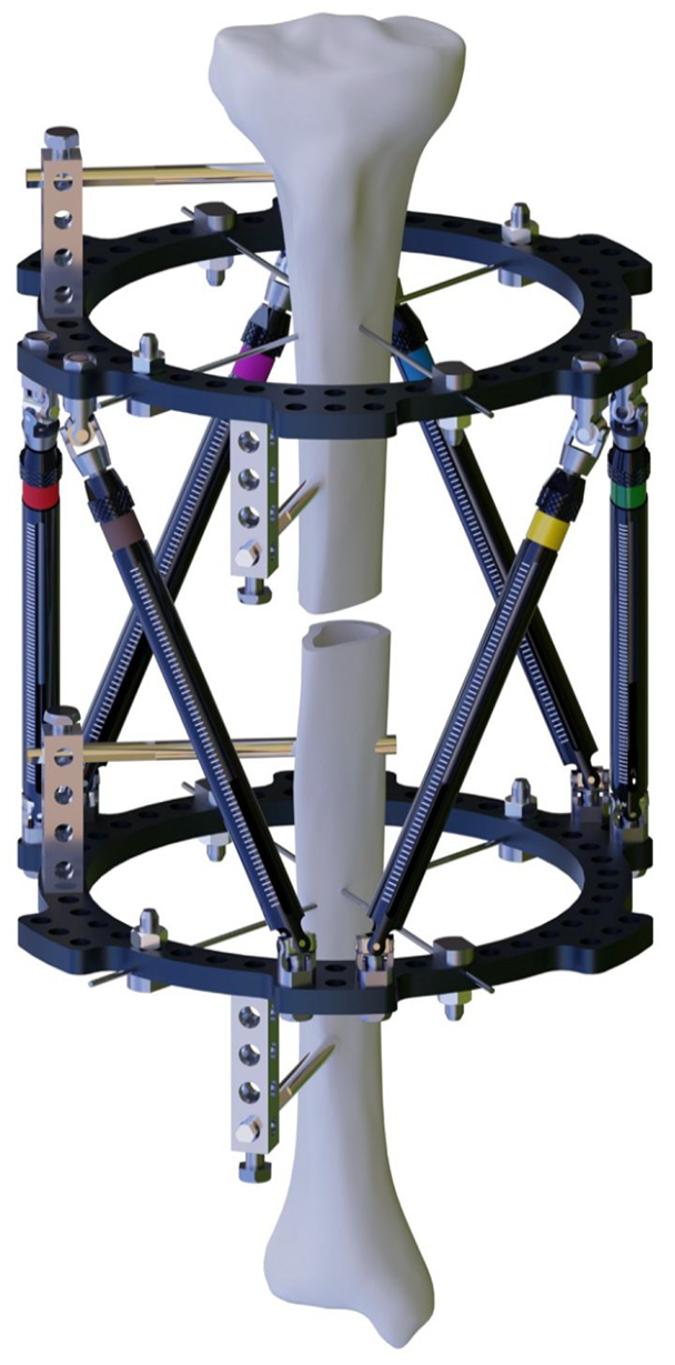
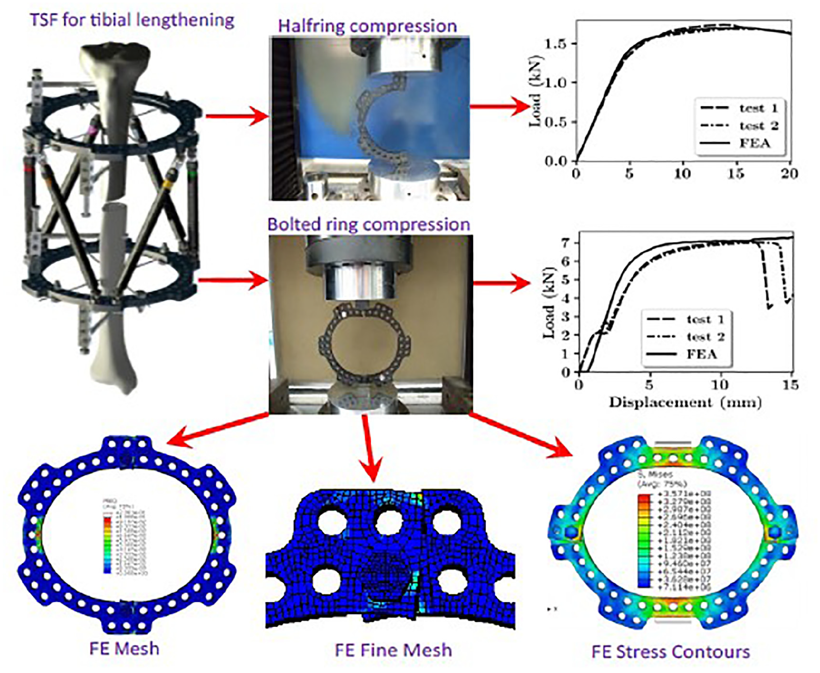
Application of a TSF for tibial lengthening.
Despite being named ‘ring fixators’, 5 the role of the rings in the circular fixation devices is not fully investigated. Rings are also the elements which make the application of tensioned wires as transosseous element possible. As the wire is tensioned, the ring is compresses, with the radial stiffness of the ring and tensile stiffness of the wire act in series. Transosseous elements are fixed to the rings. Thus, the deformation of ring can affect their behaviour, and therefore the overall performance of the fixators. 6 The mechanics of the rings is also important in predicting the mechanical behaviour of the fixator as a whole, for example, via Finite Element (FE) modelling, 7 or mathematical models.
Traditionally, stainless steel has been the material of choice for making rings in external fixators. They were also made of aluminium alloys, which were tested mechanically and reported as: ‘strong enough and well tolerated for clinical usage’. 8 Composites have also been used for making rings, including composites with woven or knitted fabric reinforcements like carbon fibre reinforced epoxy.9,10 The advantage of non-metallic ring materials is their radiolucency and lightness. Their stiffness characteristics were reported as ‘only marginally less stiff than the steel rings’. 9 Rings made of steel, aluminium alloys and carbon composites, were used in a multivariable study of the Ilizarov fixators in different modes of loading (i.e. compression, anterior-posterior and medial-lateral bending and torsion) and it was reported that: ‘materials did not affect any mode of testing’. 11 TSF rings are made of aluminium and have extra holes for attachment of the struts (as seen in Figures 1–4). It has been used in a variety of clinical cases, particularly for the reconstruction of the lower limbs.12,13,14,15,16,17,18 Research works on accuracy of the outcomes of such reconstructions have reported favourable results.19,20
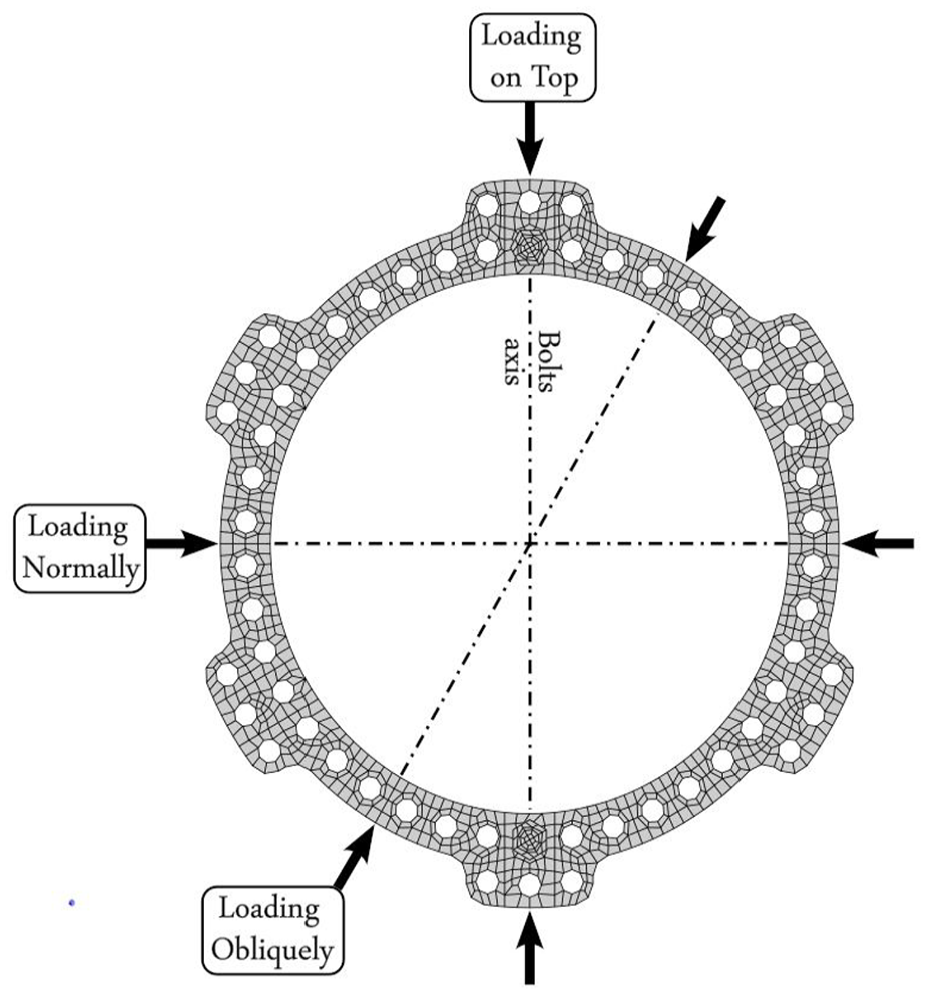
Loading directions in mechanical testing of a TSF bolted rings.
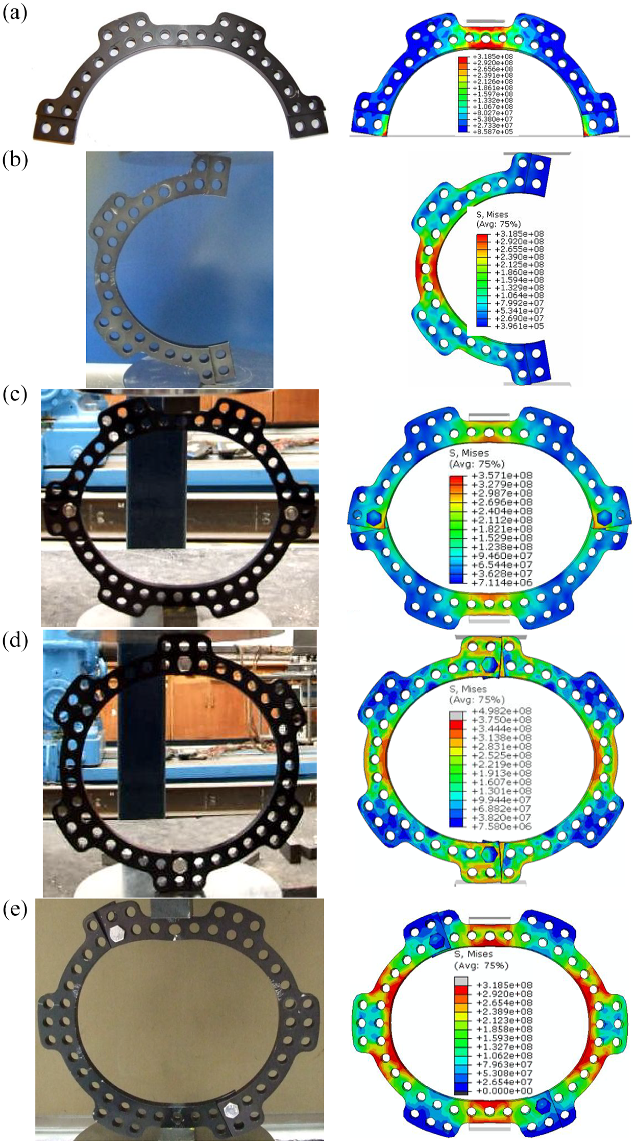
Deformed shapes of size 130 mm TSF half rings of and bolted rings from experiments and FE simulation: (a) half ring, loaded normally, (b) half ring, loaded upright, (c) bolted ring, loaded normally, (d) bolted ring, loaded on top and (e) bolted ring, loaded obliquely.
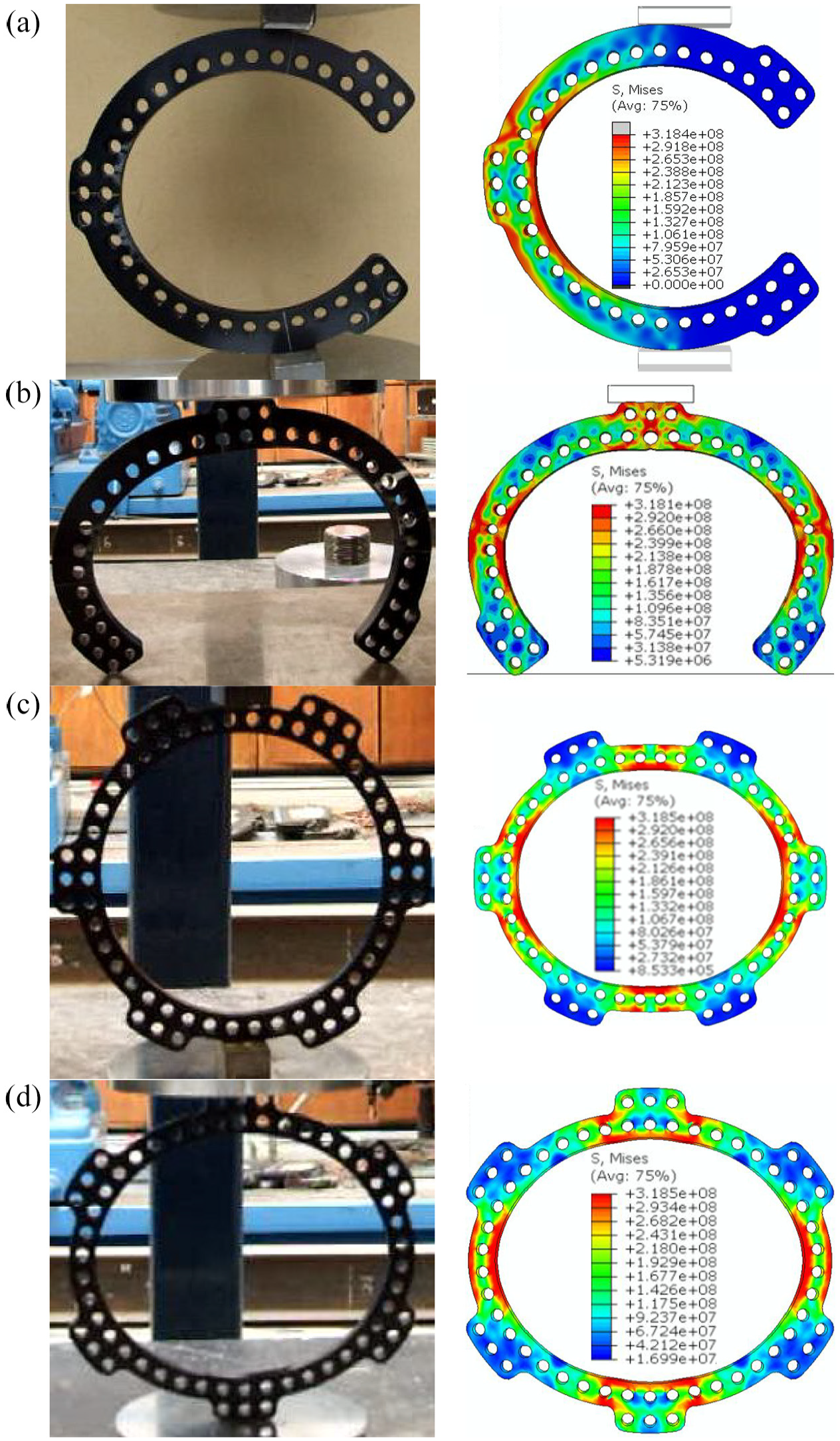
Deformed shapes of 2/3 and full rings in compression from mechanical tests and FEA: (a) 2/3 ring-loaded normally, (b) 2/3 ring-loaded on top, (c) full ring-loaded normally and d) full ring-loaded on top.
Beside material, the other determinant of the mechanical behaviour of a ring (in normal conditions) is of course its geometry. Since the shape is circular, the geometry could be reduced to the diameter. The size of a ring is indicated by its inner diameter, which is established as the most significant factor affecting fixator stiffness. 11 This is the case simply because the stiffness of the transosseous elements depends on their effective length which covers the bone-ring distance. 6
The current study was aimed at: (1) study the mechanics of the rings in the TSF with emphasis on their stiffness characteristics, deformed shapes and modes of failure under compressive loading and (2) building realistic fully three-dimensional (3D) FE models of the rings to simulate the tests and be validated against them. Such FE models of the rings could serve as the followings: (a) a virtual testing environment to fully investigate the mechanics of TSF rings, free from costs and constraints of physical tests, such as the need for special designs for a full range of loading conditions etc., (b) parts of any FE model of the full fixator and (c) a benchmark to verify simplified, hence much less computationally expensive numerical models, for example, using shell or beam element in the full range of loading and boundary conditions.
Materials and methods
Mechanical testing
Rings in ring fixation sets such as TSF, can be categorised into two main groups: (a) assembled rings, in which two half rings (also called C-rings 10 ) are bolted together to make a ring and (b) single-part rings, namely full rings and 2/3 rings, which are used as single parts. Half rings can also be used on their own. For the rest of this article, rings made of two half rings will be called bolted rings, with the imaginary line connecting the bolts named bolts axis, as shown in Figure 2.
As a curved structural element, the study of mechanics of the TSF rings should start with analysis of their behaviour under in-plane loading. In-plane compression is the loading condition which the rings are subjected to as a result of wire tensioning. The tension in the wire is increased with the transverse loading of the wires due to axial loading of the frame. 6 Therefore, rings were tested in compression as shown in Figure 2. Figure 2 illustrates the three loading conditions applied in this study: normal to the bolts axis, along the bolts axis, and at a 30° angle to the bolts axis. These conditions are named: loading normally, loading on top or upright, and loading obliquely, respectively. The ring sizes were 130 and 155 mm for these tests. Individual half rings of the said sizes were also tested in compression in two axes: along the diameter connecting their open ends as well as normal to those axes. These loading conditions are called upright (on top) and normally respectively.
In the case of single-part rings; 2/3 rings and full rings of 155 mm were tested in two axes, that is, 2/3 rings were compressed along the diameter parallel to the axis connecting their open ends, and also along the perpendicular bisector to it. The former case is called loading normally and the latter on top. Full rings were tested along their two distinct axes of symmetry: one does not pass through any of the extra holes, whereas the other does. The former is referred to as loading normally and the latter as on top.
All the components used and tested in this study were manufactured by the trademark holder of the Taylor Spatial Frame, that is, Smith & Nephew Inc. Memphis, Tennessee, USA.21,22 All tested rings were TSF ‘Aluminum Rings’ of 8 mm thickness. 22 An Instron 4507 machine was used for all the tests, in which rings were subjected to compressive loading in directions described above. Compression was applied in increments of 0.025 mm at 5 increments per second. Experimental data was acquired from the computer connected to the Instron 4507 testing machine. Data was recorded as ASCII text files containing three columns of comma separated values for: (1) increment number, (2) and displacement of the crosshead in mm (3) the load in kN. All tests were done with minimal intervention; only metal cubes of roughly 25 × 15 mm in cross section were placed between the rings and surfaces of the testing machine, when necessary, i.e. in loading conditions other than loading on top, where the row of three extra holes got in the way of aligning the sample along the desired loading axis. Each mechanical test was repeated, except for the whole full rings, whereas 155 mm bolted rings were repeated twice in loading normally and on top. Also, 155 mm bolted rings were assembled using an extra pair of bolts, which is not standard practice. They were tested to failure in loading normally and on top and the values for their stiffness and ultimate load reported. The number of the trials for each ring type and loading condition can be found in tables and figures of the results section as well.
Finite element analysis (FEA)
FE modelling and analyses were carried out using ABAQUS/CAE software package to simulate the mechanical tests. A module using Python language was developed for parametric generation of FE model for the rings, half ring and 2/3 ring. The module would take inputs such as ring diameter, thickness, depth, number of holes, diameter of holes and create the solid geometry for the ring according to those inputs. In this way, parametric study of those parameters and their effects in ring performance can be conducted. In the presented work, FE models included the following parts: 130 mm half ring, 155 mm half ring, 155 mm full ring, 155 mm 2/3 ring and also connection bolt with nuts. The depth, that is, the difference of their outer and inner radii was 20.5 mm for the 2/3 ring and 15 mm for all other rings. The thickness (normal to the plane of the ring) was 8 mm for all rings. The holes on the rings were 7 mm in diameter. The surfaces of the testing machine or the metal cubes placed between the machine surface and the rings were modelled as rigid parts. Geometrically intricacies such as fillets on the rings were reflected, to the level justified in an FE model.
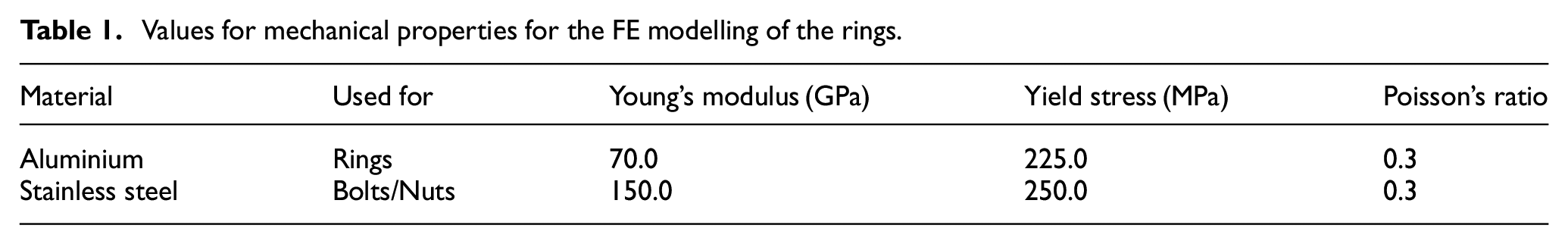
All parts, except the rigid ones, were meshed into linear hexahedral elements with reduced integration, namely the C3D8R elements from Abaqus element library. 23 The mesh quality is illustrated in Figure 2, in which two 155 mm half rings are bolted together. The thickness of the rings was divided into 4 elements, that is, each element was 2 mm thick. Elasto-plastic material behaviour was assumed for the rings, half-rings and connection bolts. Material properties in Table 1 were used in FE analyses. They are based on results from mechanical testing of sample pieces of the tested rings: pieces were machined out of the rings and tested in tension using an extensometer. Also, a connection bolt was tested in compression, with a strain gauge attached to the surface of its shaft, after removing the threads.
Values for mechanical properties for the FE modelling of the rings.
The analyses simulated the compression of the ring parts in the testing machine. One rigid body represented the moving surface forcing the ring down, and another one the surface under the ring. The latter rigid body was fully constrained, while no other boundary condition was present in the models. Contacts between all interacting surfaces were defined to avoid any interpenetration of contacting surfaces. The value of 0.2 was used for the coefficient of friction.
Results
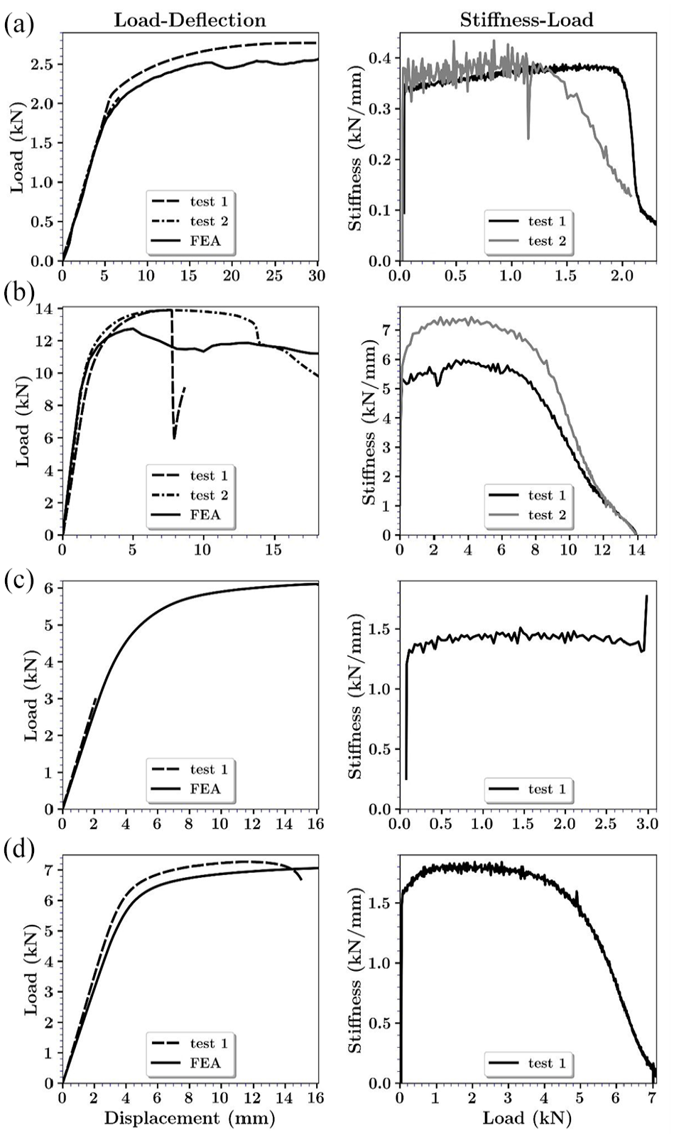
The results are presented based on the types of rings as defined above. Deformed shapes from mechanical testing and corresponding FE simulation are demonstrated in Figure 3 for the half rings and bolted rings, and for the 2/3 rings and full rings (i.e. single-part C-rings) in Figure 4. In both figures, stress contours are plotted on the deformed shapes from FE analyses, and the load directions are vertical. Ring sizes are 130 mm in Figure 3 and 155 mm in Figure 4. Figure 5 shows load-deflection curves for half rings and bolted rings from the tests and the corresponding FE analyses. From each load-displacement curve obtained from mechanical tests, stiffness was calculated as the derivative of the applied load, with respect to displacement. Stiffness-load curves were preferred to stiffness-displacement curves. The fact is that in practice the displacements are unknown, while loads can be estimated, for example, during the tensioning of the wires, which would make stiffness-load graphs more relevant. Stiffness-load curves obtained from the data used in Figure 5 are plotted in Figure 6. For 2/3 rings and full rings, load-deflection and stiffness-load curves are plotted in Figure 7.
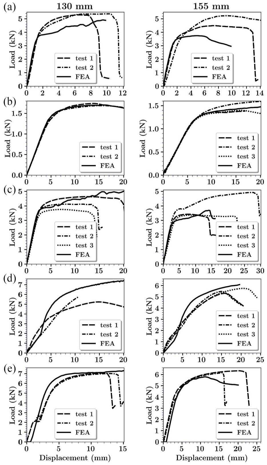
Load-deflection graphs from mechanical tests and FE analyses of the TSF Half rings and bolted full rings: (a) half ring, loaded normally, (b) half ring, loaded upright, (c) bolted ring, loaded normally, (d) bolted ring, loaded on top and (e) bolted ring, loaded obliquely.
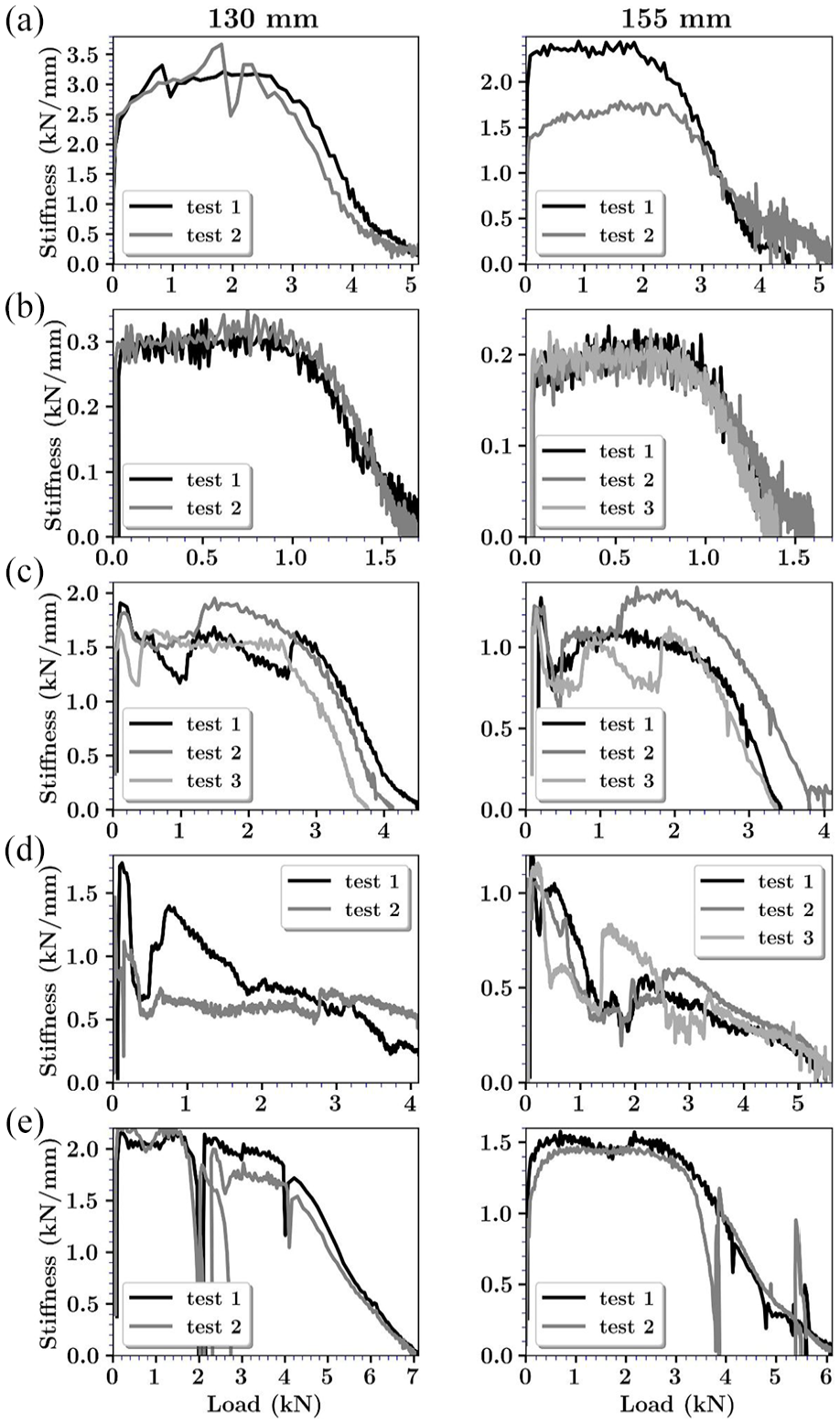
Stiffness-load graphs from mechanical testing of TSF half rings and bolted full rings: (a) half ring, loaded normally, (b) half ring, loaded upright, (c) bolted ring, loaded normally, (d) bolted ring, loaded on top and (e) bolted ring, loaded obliquely.
Load-deflection graphs from experiments and FEA on 155 mm 2/3 and full rings (left column) alongside the corresponding stiffness graphs from the experiments (right column): (a) 2/3 ring-loaded normally, (b) 2/3 ring-loaded on top, (c) full ring, loaded normally and (d) full ring-loaded on top.
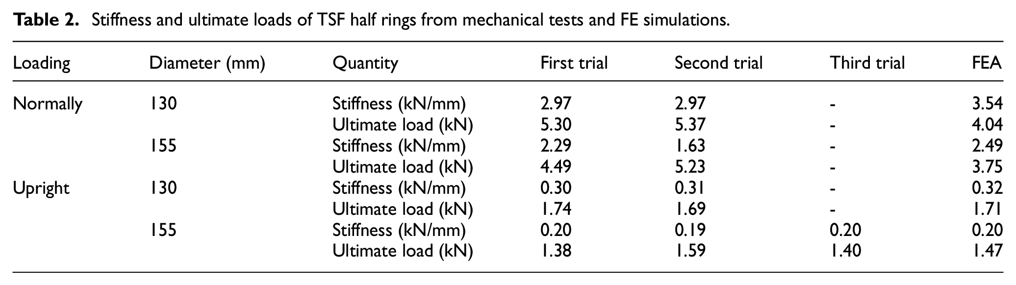
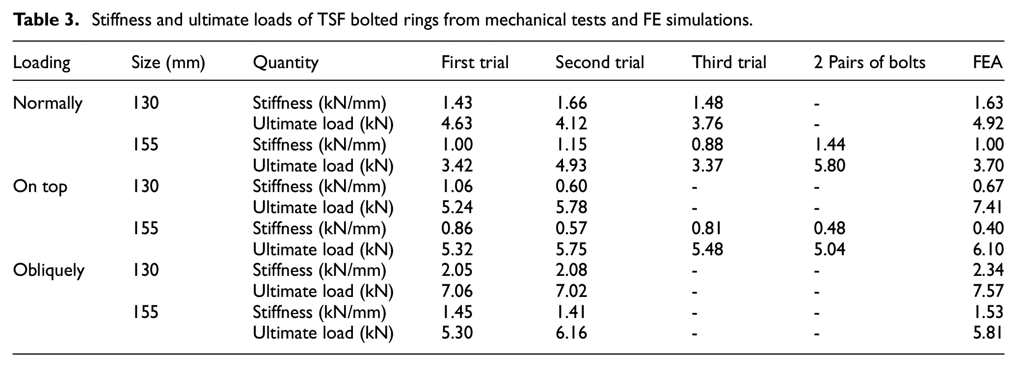
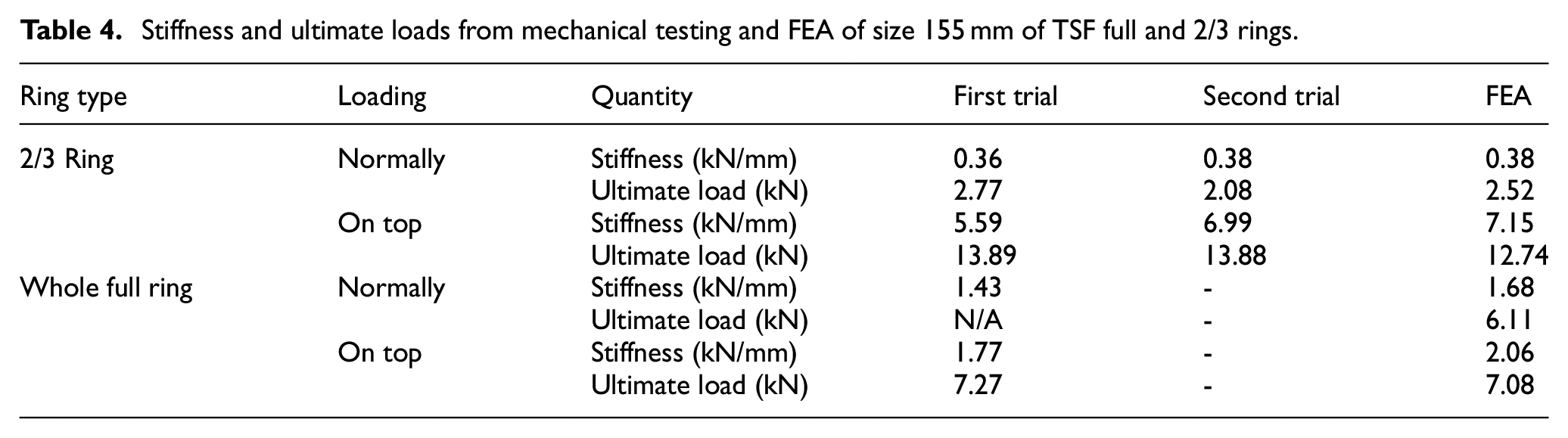
Values for stiffness were estimated as the slope of the linear parts of the load-displacement curves in Figures 5 and 7 for tests and FEA, and are presented in Tables 2 and 3 for half rings and bolted rings respectively and in Table 4 for 2/3 and full rings.
Stiffness and ultimate loads of TSF half rings from mechanical tests and FE simulations.
Stiffness and ultimate loads of TSF bolted rings from mechanical tests and FE simulations.
Stiffness and ultimate loads from mechanical testing and FEA of size 155 mm of TSF full and 2/3 rings.
Half rings loaded normally
In these tests half rings were compressed normal to the axis connecting their ends. The deformed shapes are demonstrated in Figure 3(a). The results for load-deflection are plotted in Figure 5(a), where the FEA results are shown to have over-predicted the experimental results in the elastic region. For the plastic region, FEA results are not reliable in this case, due to ensuing large displacements of the ends of the half-ring on the underneath surface, which makes the results dependent on the friction. This has also made its effect shown in Figure 6, as sudden changes in the stiffness in the elastic region (load < 3 kN) for both trials which could as well be due to sliding of the ends of the half ring on the surface underneath. As the friction or sliding (between the half ring and the surface) could only affect this particular test, the effect of friction was not further investigated. It should be noted that the effect of the friction and sliding between the ends of the half-rings and the testing surface was not a primary objective. The primary objectives were to examine the modes of deformation and stiffness characteristics of a single half-ring when subjected to a load along the direction orthogonal to the line joining its two ends. Of great interest was to observe whether there was an out-of-plane deformation, but none was observed.
Half rings loaded on top (upright)
In Figure 3(b) damage to the ring is visible in the form of the marks on both sides of the middle hole in the half rings. Figure 5(b) demonstrates very close agreement between test and FEA results. Table 2 shows that the stiffness given by FEA is very close to those from experiment. Stiffness curves in Figure 6(b) demonstrate an orderly pattern. Figure 3(b) shows that stresses occur overwhelmingly at middle of the half rings, leaving its ends virtually stress-free except for the local stresses at the contact points with the machine surfaces. This means that the ends of the half rings have mainly rotated (inward) rather than being deformed.
Bolted rings loaded normally
Figure 3(c), when compared to the deformed shapes of individual half rings in Figure 3(a), shows that the individual half rings in the bolted ring have deformed and failed similarly to a half ring when loaded normally. Figure 5(c) shows that for the linear elastic portion of the curves, the FEA results follow those from the tests very closely and underestimate them in plastic region. Figure 8(a) shows an orthogonal top view of the deformed shape in Figure 3(c), as well as the deformed shape of a connection bolt with contours of plastic strain plotted on it. It shows no sign of out of plane deformation or twist or torsion in the ring. Only limited plastic damage in the connection bolt is observed in the middle of the body of the bolts, which is fitted inside the ring hole. In terms of stiffness-load behaviour, Figure 6(c) shows irregularity in stiffness-load curves for this case.
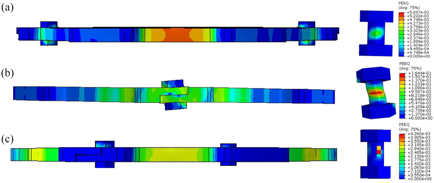
Stress levels on deformed shapes of 130 mm bolted rings with plastic strain levels on their bolts: (a) loaded normally, (b) on top loaded, and (c) obliquel loaded.
Bolted rings loaded on top
As mentioned before, when an individual half ring was compressed along the axis connecting its ends, both its top and bottom ends tend to turn inwards (see Figure 3(b)). In the case of a bolted ring compressed along its bolts axis, this rotation in precluded by the connection bolts. The fact that the bolts were fitted in the inner common hole of the two half rings, results in the outermost edges of the half rings being pressed against their opposite surfaces, which causes excessive stresses and local failure there as seen in Figure 3(d). The opposite is the case for the inner part of the ends of the half ring, that is, they are being pushed apart from one another. Because the inner holes are fitted with the connection bolts, the body of the bolts were subjected to two opposing forces which therefore causes a couple as well as a shearing load. The couple made the bolts twist, and its reaction was applied to the half rings making the ring twist slightly around the bolts axis. These effects are noticeable in Figure 8(b), which illustrates the top view of the deformed shape in Figure 3(d) alongside the plastic strain levels on one of its connecting bolts. In Figure 3(d), stress levels on the deformed shape from FEA show that highest levels of stresses have developed in the middle of the half rings. Figure 5(d) shows the nonlinear nature of load-deflection behaviour in this test. This interaction of the bolts and the half rings makes the load-deflection behaviour deviate from a linear relation, and even in low levels of the applied load, it is not easy to assume linearity for the load-deflection relation. In the FEA results shown in Figure 5(d), there is a clear linear part at the start, that is, before the bolts get engaged in the deformation and then the nonlinearity begins when the bolts start to be deformed and twisted as shown in Figure 8(b). In the curves from the test trials however, there is no clear starting point for the nonlinearity and therefore no clear starting point for the involvement of the bolts is assumed. This should be born in mind when considering the estimated values for stiffness in Table 3. Figure 5(d) shows that FEA prediction is reasonably close to experimental results in its linear part and will diverge from experimental results beyond its linear range. Figure 6(d) hardly shows any regularity for stiffness behaviour.
Bolted rings loaded obliquely
Figure 3(e) shows that the ring has fractured at the loading site after undergoing considerable plastic deformation. Figure 3(e) also shows that in the deformed shapes, the upper half ring has slid downwards along the bolts axis (see Figure 2) over the lower half ring. In Figure 8(c), orthogonal top view of the deformed shape in Figure 3(e) is illustrated together with results for plastic strains plotted on the deformed shape of a connection bolt, where of the ring shows no out-of-plane deflection, twist or torsion. The plastic strain levels on the deformed shape of the connection bolt show that the damage to the bolts has been insignificant. This is important, because had the bolts undergone considerable plastic deformations (like the case with the rings loaded on top), the overall stiffness of the ring could have been affected. In Figure 6(e), for both trials on the 130 mm ring, an irregularity appears right above the 2 kN marks, as if the curve has been broken and shifted to the right by a certain amount (roughly 1 mm), like a deflection with little increase in the load. This happened when the upper half ring suddenly slid over the bottom half ring and is visible in the deformed shapes in Figure 3(e). For the case of FEA, this sliding phenomenon occurred at the onset of the loading, which is also observed in Figure 5(e), as if the load curve has started with a delay (lag). This can be explained as follows:
As the bolts are tightened, the level of static friction develops between the contacting surfaces of the pair of half ring and between bolt heads and nuts and the half rings. This will prevent any sliding up to the static friction threshold, which ostensibly has been almost 2 kN for the case of 130 mm rings here. As the load surpasses this threshold, contacting surfaces start to slide. The sliding occurs because the bolts do not fully fill the holes. In fact, they have a diameter of 6 mm (they are M6), while the ring holes have a diameter of 7 mm. The sliding then stops when the body of the bolts comes into contact with the inner surfaces of the holes. After that, the load-deflection curves appear to have been resumed virtually with the same slope. Figure 6(e) shows an orderly stiffness pattern prior to the sliding, then stiffness suddenly dropped to zero and picked up again afterwards. Figure 5(e) shows that the sliding has occurred at the onset of the FEA load-deflection curve, having a smaller size than those in the tests. The FEA results show the same for the 155 mm ring as well. However, results from tests show a similar effect for the 155 mm size, only in the second trial and towards the end of elastic region.
Table 3 shows that the stiffness is over-predicted by FEA by an average of over just 10%. Yet from Figure 5(e), it can be argued that the apart from the initial lag in the FEA results, they follow the same trend as the test results.
Bolted ring with two pairs of bolts loaded normally
To test the effect of an additional pair of bolts on the behaviour of the bolted rings when loaded normally, two 155 mm TSF half-rings were bolted together using two pairs of bolts. Results for stiffness and ultimate load for this test are listed in Table 3, under ‘2 pairs of bolts’.
Bolted ring with two pairs of bolts loaded on top
In a test similar to the above, a TSF bolted ring was assembled with two pairs of bolts and was loaded on top. Stiffness and ultimate load from this test are also included in Table 3.
2/3 ring loaded normally
Figure 7(a) shows that the second test covered the elastic region but does not show the full plastic region leading to failure. However, for the first trial, it is seen that the ring continued to deform plastically even beyond 30 mm of displacement. This excessive plastic deformation prior to failure is due to the open section of the two-third rings. A similar behaviour was observed for the half rings loaded on top shown in Figure 5(b) for the 155 mm half ring. In Figure 7(a) the stiffness-load graph shows orderly stiffness behaviour over the elastic range, and the load-deflection curves from the test and FEA coincide for the elastic region. In the plastic region however, the FEA curve fell under that of the second trial of the test.
Table 4 has the stiffness and ultimate load values. Results show that although 2/3 rings are made thicker, still not strong enough, and probably need strengthening in their middle as deformed shapes in Figure 4(a) suggest it as the location where plastic deformation initiated and was mostly limited to the region around the middle five holes of the ring.
Full ring loaded normally
Figure 7(c) shows the load-displacement curve from the test, which stopped before getting into the plastic region, and thus no maximum load as recorded. It shows that the FEA overestimate the physical test results. The difference can be obtained from Table 4 as 17%.
2/3 ring loaded on top
Figure 7(b) shows very good agreement between the FEA results and those from the tests within the linear elastic domain. Nonetheless, for the pastic region it underestimates the test results. The stiffness-load curves in Figure 7(b) show an orderly stiffness behaviours. Table 4 presents the calculated values for stiffness and the ultimate loads. This case may lack practical relevance; however, it helps validate the FE model.
Full ring loaded on top
Figure 7(d) shows regular and orderly stiffness behaviour and also that the general trend of the curve corresponding to FEA is similar to that from the test. Table 4 has the values for stiffness and maximum load from the test and the FEA. It shows that FEA yielded an overestimation of 17% for the stiffness and underestimation of 10% for the ultimate load.
Material behaviour and failure
The observed material behaviour was as of a typical ductile metal: large plastic deformations in form of barrel-like bulging in compression and necking in tension, before rupture. Figure 9 shows a close view of such deformations in the middle of a 130 mm half rings loaded normally – as shown in Figure 3(a)– from both physical test and FEA. In Figure 9, the inner rim of the half ring is shown to have necked under tension, while the outer rim shows a barrel-like swelling in compression. The reverse was the case for the half rings loaded upright. In Figure 9 the marks on the ring, resemble the plastic strain contours in the FEA results shown, both of which visually illustrate the damage to the material.
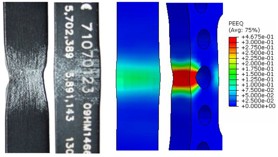
Necking and barrel-like deformation on a 130 mm half ring loaded normally.
Discussion
Based on the results, the following points can be made regarding the stiffness of the rings:
Stiffness in bolted rings and half rings
When two half rings are bolted and compressed in the same direction, the load is divided between them, and they deform simultaneously and by the same amount. This is the definition of two stiffness in parallel, that is, k eq = k 1 + k 2 , where k eq is the equivalent stiffness (of the parallel configuration) and k 1 and k 2 are the individual stiffness values. Comparing stiffness values in Table 2 to those in Table 3, shows that the stiffness of a bolted ring loaded on top is slightly higher than double the stiffness of an individual half ring loaded the same way. The excessive deformation and damage undergone by the bolts in loading a bolted ring on top (see Figure 8), obviously contributes to the stiffness of the ring, elevating the stiffness of the bolted ring above the sum of the individual half rings.
In a similar fashion, it can be argued that when a bolted ring is loaded normally, its two half rings behave as two stiffness in series, that is
It should be emphasised that the tests on individual half rings (subsections 3.1 and 3.2) have no relevance except that they reveal the behaviour of individual half rings in a similar loading condition to the tests on bolted rings (subsections 3.3 and 3.4).
Effect of different loading conditions on stiffness
From the stiffness values given in Tables 2 to 4, it is clear that the stiffness varied significantly with the direction of load in the following ascending order: loaded on top, loaded normally and loaded obliquely. The reason is; as described just above as well as in the Results section, the behaviour of bolted rings in any loading condition depends on the behaviour of individual half rings under that loading condition. The half rings are weakest when loaded on their top (upright), because they are loaded along their open section. A half ring not loaded parallel to its open section, is at its weakest, when loaded normally. The reason is when loaded in obliquely, the arc lengths on one side of the point of application of the load will be smaller, and therefore stiffer. Comparing the curves on stiffness-load graphs for three different loading conditions showed similar trends for both ring sizes under the same loading condition. For bolted rings, the stiffness-load graphs showed more orderly stiffness patterns for the oblique loading condition and the most erratic behaviour when load was applied on the top.
Effect of an extra pair of bolts on stiffness
Thanks to the extra holes in the TSF which are devised for attaching the struts, to assemble the half-rings together, there are two holes on each side for placing the bolts. Two tests were conducted with two pairs of bolts joining two half rings to check the effect of an additional pair of bolts in mechanical behaviour of the TSF rings. The first test, as described above, was a case of a ring being loaded normally and in the second one, the load was applied on top. The results for stiffness and ultimate load are listed in Table 3.
The results for loading on top showed no improvement for stiffness with the introduction of the extra pair of bolts. The stiffness in fact has decreased, which can also be due to the absence of a clear linear region in load-deflection curves from the tests in loading on top, as can be noted from Figure 5(d). For the case of loading normally, Table 3 shows a significant increase in stiffness in this type of loading with two pairs of bolts.
The difference in the effect of an extra pair of bolts for the two loading conditions can be attributed to their respective mode of deformation. In Figure 3(d) it is clear that when using only one pair of bolts, no deformation occurs at or around free holes, therefore filling those holes would not affect the behaviour of the ring. In Figure 3(c), however, it is clear that when the bolts are placed on the inner holes, its adjacent outer hole is free and will allow the outer tip of the half ring to tilt. The additional bolts prevented this from happening which led to higher value for stiffness. Using hole fillers around the bolt shafts, which fully fit and fill the holes, may also improve the stiffness of the bolted rings.
Effect of ring sizes on stiffness
Comparing the stiffness values given in Tables 2 and 3 for 130 and 155 mm rings reveal that the stiffness for the 130 mm ring is more than 40% higher than that of a 155 mm ring. This is of course due to the fact that the deflections in curved beams are roughly proportional to the inverse of the second power of their radii. Here (155/130) 2 = 1.41 as the cross section and second moment of area remain the same (constant EI). It is though counter-intuitive to have the smaller rings stronger than the larger ones, as the smaller rings are used for patient with smaller limbs and thus the rings which undergo larger loads are weaker and the rings which are under small loads are stronger. This would certainly be magnified for larger ring sizes, that is, 180 mm rings and larger. This means that having the same thickness and cross section for all ring sizes is not justified given the large variation in ring sizes (from 130 to 220 mm). They will either be too large for smaller patients or too weak for larger ones or possibly both.
Effect of geometry of the rings on stiffness
Comparing the results from bolted 155 mm rings to those from a full ring of the same size, points to an essential difference. Stiffness values in Tables 3 and 4 show that in loading on top, the stiffness drops from 1.77 for a full ring, to an average of 0.75 (with a maximum of 0.86) for a bolted ring, and in loading normally from 1.43 to an average of 1.01 (with a maximum of 1.15). Due to its symmetry, the full ring lacks an equivalent for loading obliquely. However, the average stiffness from all tests for bolted rings is 1.06 compared to 1.60 for the full ring. The picture becomes clearer when stiffness-loads curves are also compared. However, the fact that having two half rings instead, has the advantage of flexibility of application, for example, they are easier to adjust or remove temporarily if need be.
Results on the 2/3 rings show that although they are made thicker than full rings and half rings, they still exhibit the inherent weakness due to their open section. The stiffness pattern in load-stiffness curves also is an indicator of well-behaved stiffness of the specific ring geometry. Scope here is limited to in-plane deformations of the rings. 2/3 rings would obviously be stronger in out of plane deformations due to their larger thickness.
The scope of this research was not extended to environmental factors like temperature or humidity or mechanical phenomena such as wear, micro-damaging or fatigue. Nonetheless, these are not likely to affect the performance of the rings in a significant manner, given the relevant properties of the materials and the high quality of manufacturing (individually numbered and marked parts, as seen in Figure 9). The reuse of the rings is not recommended by the manufacturer, which further minimises effects such as wear, micro-damage buildup and fatigue.
Conclusions
In this study, mechanical tests were carried out on TSF rings to determine their stiffness characteristics as well as modes of deformation and failure. Half rings, whole full rings, 2/3 rings and full bolted rings were subjected to in-plane compression along two or three different directions. FE models of the parts were made and used to simulate the experimental tests. The FE results showed good agreement with those from the tests, especially for the elastic range, which is supposed to covers the clinically applied load range. The results revealed that the in-plane stiffness of TSF bolted rings depend on the direction in which they are loaded. It was observed that whole full rings exhibited higher stiffness, and that their stiffness-load curves were also more orderly. Thus, whole full rings should be recommended where clinically applicable. A potential problem in the rings germane to their constant thickness and cross section for all ring diameters was also noted. Modes of deformation and failure as well as load-deflection curves for each case were presented and discussed. The FE models, verified by experiments, can be used to predict mechanical behaviour of the rings under more complex loading conditions. They can also be integrated into FE models of the full TSF fixators.
Footnotes
Acknowledgements
The award of a part scholarship from the School of Mechanical, Aerospace and Civil Engineering to Ahmad Zamani is gratefully acknowledged. Furthermore, the authors wish to express their gratitude to Mr David Mortimer for his help, support and advice in all aspects of the mechanical tests in this study.
Declaration of conflicting interests
The author(s) declared no potential conflicts of interest with respect to the research, authorship, and/or publication of this article.
Funding
The author(s) disclosed receipt of the following financial support for the research, authorship, and/or publication of this article: The award of a scholarship from the School of Mechanical, Aerospace and Civil Engineering to Ahmad Zamani is gratefully acknowledged.