
Abstract
In winter, some freight trains with composite brake blocks experience unexpected long braking distances, which seriously jeopardizes running safety. The reasons for the long braking distances are still not completely understood, and therefore it is difficult to suggest preventive measures. Up to now, it has not really been studied how a layer of ice that is often found between the brake block and the wheel influences the braking process. To investigate whether ice influences the braking distance, a numerical model is built. Ice thickness, ambient temperature, initial speed, and axle load/brake pressure are parameters that can be varied in the model. Results are checked against available on-track tests. The simulation results show that ice significantly influences the braking distance. The impact of ice on the braking distance increases when the ambient temperature, initial speed, and brake pressure are low, which is consistent with available field test reports. The results also show that a conditioning brake, a high brake pressure and a small clearance between the wheel and brake block can efficiently reduce the impact of ice on the braking distance of freight trains with composite brake blocks in winter.
Introduction
Railway freight transport has a high transport capacity and is environmentally friendly. In 2020, in the EU, 366 billion ton-kilometres of goods transport were achieved by freight trains. The brake system of freight trains is important because it is safety-related. Most freight trains are equipped with block brakes because they are cheap and have a good braking performance. The structure of the block brake is shown in Figure 1(a). The blue arrows show the spinning velocity of the wheel and the direction of the compressive force, and the brake block is in yellow. When the braking starts, the brake block is pressed against the wheel, so the kinetic energy is transformed into friction heat at the wheel-block interface. (a) Sketch of block brake system for a wheel; (b) Brake block covered with ice.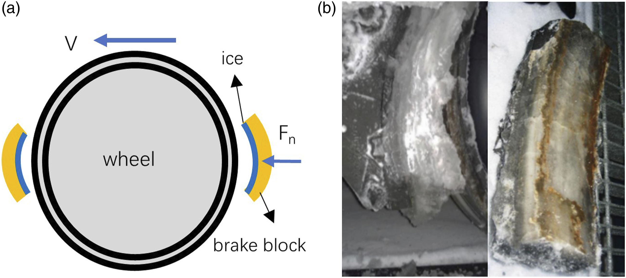
Cast iron is one of the main materials used for brake blocks, which has a high thermal conductivity. However, cast iron brake blocks are prone to generating significant noise because they result in fairly high roughness on the wheel tread, partly owing to material transfer from brake block to wheel tread. 1 Instead, composite material which is made of resin, fibre and metal, is widely replacing cast iron today because of its low brake noise and high wear resistance. 2 The International Union of Railways (UIC) wants the European freight wagons to use composite brake blocks to reduce braking noise, 3 but some Nordic railway operators reported that the wagons equipped with composite brake blocks experienced unexpectedly long braking distances in winter. 4 The problem is more significant at temperatures below −15°C, with empty wagons,5,6 and at low speeds. 7 To prevent severe accidents, some freight trains have to lower their operational speed, which decreases line capacity and increases running times. 6 According to Trafikverket (the Swedish transport administration), about 15% of the railway freight transport would shift to the road or sea in Sweden if the operational speed of freight trains is reduced from 100 km/h to 80 km/h. 7
In order to address the reason for the long braking distance of composite brake blocks in winter, many studies have been performed. Tribology research shows that the coefficient of friction (COF) of composite material is sensitive to water. 8 A laboratory test 9 shows that composite material has a much smoother surface and a lower COF under snowy conditions than cast iron. Tribological research concludes that the reason for the long braking distance of composite brake blocks is the material properties, but composite brake blocks can still maintain acceptable braking performance with a conditioning brake applied (slight braking every 10 minutes or 15 km). The conditioning brake does not change the brake block material properties, which means that removing snow and ice between the wheels and brake blocks is essential to maintaining a good braking performance. In field tests, 10 it was observed that the brake lags change with the condition of bedded-in of brake blocks (the term ‘bedded-in’ means that the geometry of the brake block at the friction surface becomes the same as the geometry of the wheel so that maximum contact is achieved. Through reference 10 , the well bedded-in condition is related to significant wear of the brake block). The slightly bedded-in blocks have nearly no wear on the blocks while the heavily bedded-in blocks are worn blocks. The slightly bedded-in blocks maintain a small clearance between the brake block and wheel because the thickness of these blocks is still high.
Existing research cannot explain the relationship between braking distance and ambient temperature, initial vehicle speed and axle load/brake pressure very well. One phenomenon that is often neglected is a layer of ice between the brake block and wheel, which may influence the braking performance. As shown in Figure 1(b), the friction surface of the brake block is covered entirely by ice. In reference 5, this layer of ice is considered, and it is assumed that ice melts to water immediately when braking starts. How ice is removed and for how long time ice stays on the block surface during the braking process needs to be studied. The COF between ice and steel is low, i.e. about 0.03, 11 which limits the utilized brake force, while the COF for brake block and wheel is nearly 0.2.8,9 Whether there is ice on the block friction interface or not seems to have an important impact on the braking distance.
In this work, a numerical model to investigate the relationship between braking distance and ice thickness, ambient temperature, initial speed and axle load/brake pressure is developed. Based on the model, a parametric study is performed, and measures to improve the braking performance of composite brake blocks are suggested.
Modelling
On-track tests are usually costly and may be risky since they could result in serious accidents or even casualties. Therefore, a numerical study is an economical and efficient way to study rail vehicles' braking performance. The braking process involves mechanics and heat, which is a multiphysics process and is difficult to couple with a finite element method model, therefore a mathematical model is built and solved using Matlab.
Configuration of braking system
As shown in Figure 2(a), a standard two-axle freight wagon with a 20 t axle load is modelled. The block brake and vehicle parameter details are from UIC-code 544-1.
12
Figure 1(a) shows a diagram of the block brake system for a single wheel. (a) Configuration of a standard two-axle wagon; (b) COF of the whee-block interface with/without ice.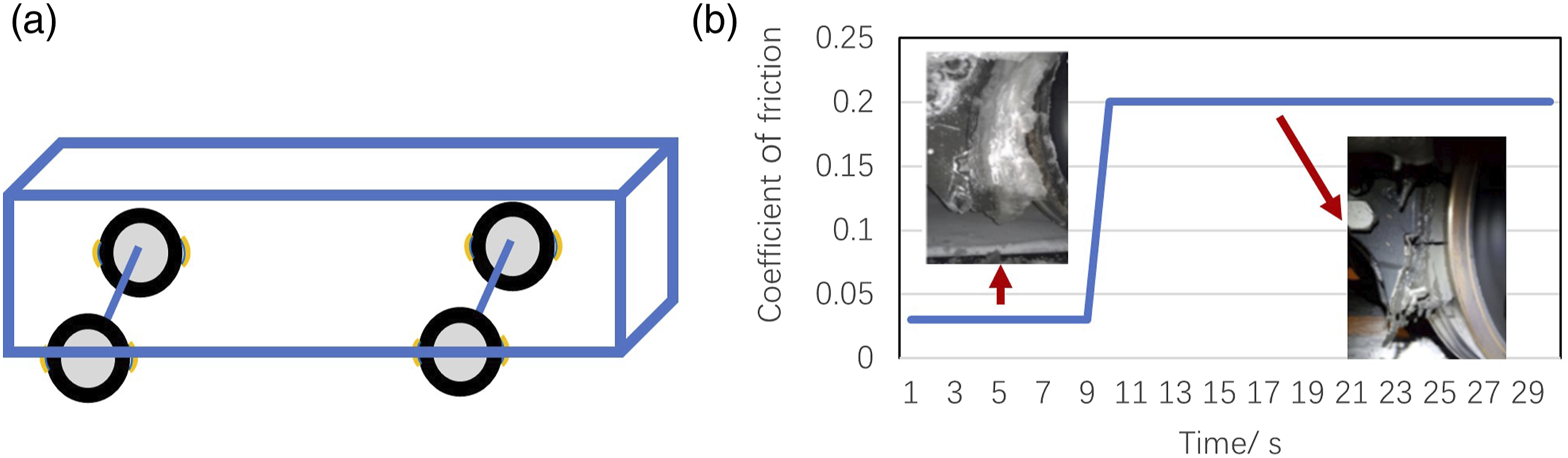
Coefficient of friction
There are many observations of a layer of ice between the wheel and brake block. 5 In our model, we assume that ice exists at the wheel-brake interface before braking starts. As shown in Figure 2(b), when there is a layer of ice on the interface, the COF between the brake block and wheel is low. 11 After the ice is removed, the COF increases.8,9
Strength of ice
During breaking, ice on the brake block is mainly crushed by the compressive forces exerted on it by the wheel. However, ice cannot be removed from the brake block when its compressive strength σ ice, shear strength τ ice , and adhesion strength δ ice are larger than the compressive stress σ brake and shear stress τ brake exerted by the brake.
As shown in Figure 3, ice grows on the interface of the brake block. When the train starts braking, the brake block and ice are pushed against the wheel. Ice is subjected to compressive stress Compressive, shear, and adhesion strengths of ice.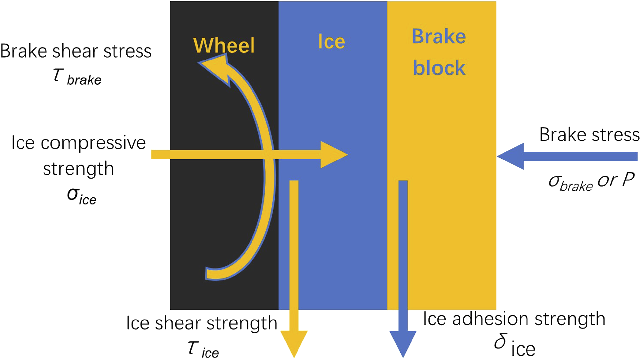


The brake pressure of freight trains changes with axle load.
5
In most studies, the brake pressure is taken as 0.8 MPa.8,13–15 Ice compressive strength
16


How ice is removed from block brakes also depends on the adhesion strength of ice, δ ice . Adhesion is the attraction between two surfaces. Composite materials have higher adhesion strength δ ice than cast iron. The ice adhesion strength of cast iron is nearly 0.5 MPa. 18 The adhesion strength between composite materials and ice is almost the same as the ice shear strength τ ice . Composite materials have good wettability and good water absorption ability,5,8,16 which allows water to permeate deeper into them.
Friction between the wheel and ice generates heat at the interface, so the compressive strength σ ice and shear strength τ ice of the thin layer of ice on the friction interface decrease when the temperature rises. Friction heat has little influence on the ice adhesion strength δ ice because the ice layer has poor thermal conductivity. The ice layer which sticks to the surface of the brake block has almost the same temperature as the ambient temperature.
Friction heat
The block brake transforms kinetic energy into heat at the wheel-block interface by friction

Since there is a layer of ice on the brake blocks, friction heat is generated and transferred to the wheel. The friction heat flow rate of the wheel is
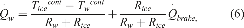
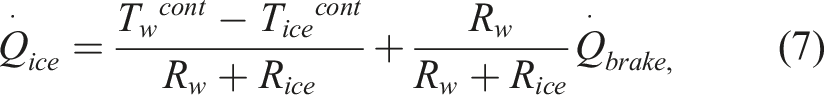
Assuming the temperatures of the wheel T w cont and ice T ice cont are the same and constant before braking, only thermal resistance influences the heat distribution. Thermal resistance is the inverse of thermal conductivity. The thermal conductivity of the wheel is nearly 59.17 W/mK, 19 and that of ice is 2.35 W/mK. 20
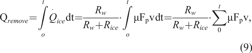
Determining how much heat is generated and how long time it takes to remove all the ice at the wheel-block interface is crucial to determine the braking distance. The needed amount of heat used to remove ice is


The ice crush temperature is calculated by the brake pressure

Calculation of braking distance
The method used to calculate the braking distance for freight wagons is specified in UIC 544-1. 12 The main difference between the UIC code and this model is the COF between the wheel and brake block. When ice exists on the wheel-block interface, the COF is low. Once there is enough friction heat to remove the ice, the COF increases because the brake block is directly in contact with the wheel. Determination of the time needed to remove the ice layer is the key feature of this model.
Figure 4 is the algorithm of the model. First, we input the initial speed V(i),i = 0, and the aim speed V(aim). I is the time step. The aim speed for a train that should come to a stop is 0 km/h. Second, we calculate the brake force F(i) between the brake block and wheel. μ is the COF, and Fb(i) is the applied force from the brake block to the wheel. Third, we compare whether the brake force F(i) is larger than the maximum available brake force(mgα+W(i)). α is the rail and wheel adhesion. mgα is the available adhesion force. W(i) is the running resistance.
21
If the brake force F(i) is larger than the available adhesion force, the wheel will slide. Wheel slide is defined as the wheel’s angular speed being different from the train’s speed, and this phenomenon should be avoided to protect the wheel and track from severe wear. Fourth, according to the available brake force, the train’s deceleration a(i+1) and speed V(i+1) are updated. The relationship between brake force and resistance force to deceleration is Calculation for braking distance with brake blocks covered with ice.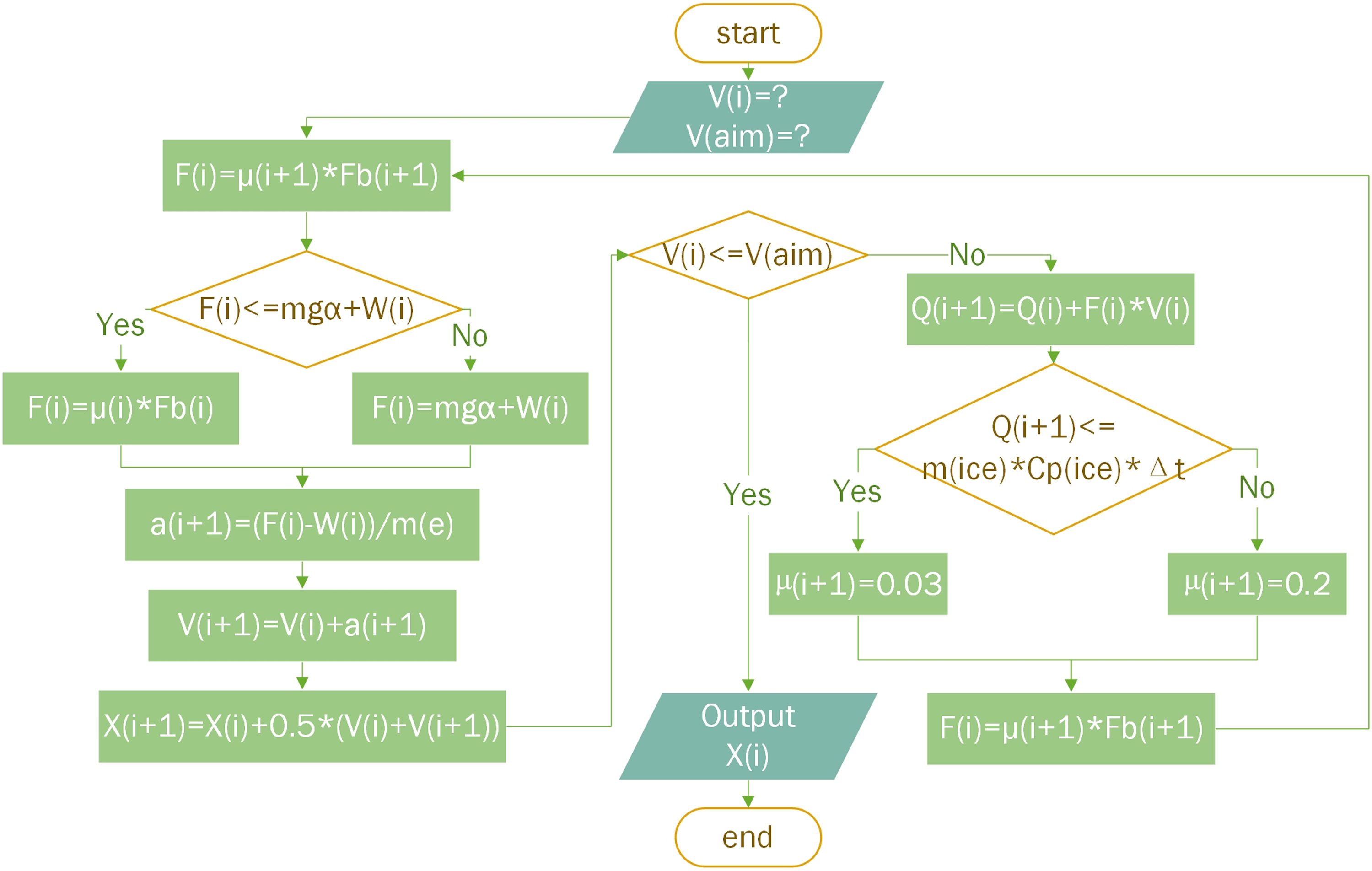

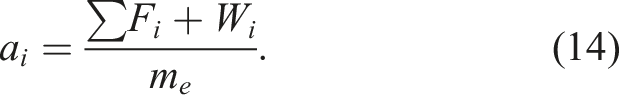
Once the deceleration is known, the instantaneous speed of the train is

To calculate the braking distance during time interval Δt, the mean speed is
Then the braking distance covered during the time interval Δt is

The sum of the braking distance of each time interval is the total stopping distance

Then, we compare the current speed V(i) with the aim speed V(aim). if the train is still running, we compare whether the friction heat is high enough to move the ice. If there is still ice on the surface of the brake block, the COF is low; if there is no ice, the COF increases. Finally, we update the brake force according to the COF. The loop will continue until it reaches the aim speed.
Scenario description
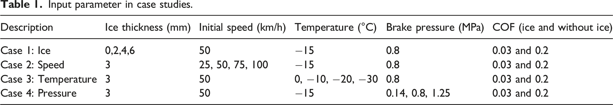
Based on the above model, the following cases are studied to understand the effect of an ice layer on the braking performance of freight wagons. The modeled wagon is a standard two-axle wagon with a 20-tonne axle load. For case 1, the ice thickness is assumed to be 0, 2, 4, and 6 mm. The maximum clearance from the wheel to the brake block is 7 mm. 22 Case 2 investigates four initial speed conditions ranging from 25 to 100 km/h. 5 shows that most of the accidents with long braking distances happened at ambient temperatures below −15°C. Therefore, the studied ambient temperature varies between 0 and −30°C. For case 4, the three brake pressure conditions range from 0.14 MPa (for an empty wagon with 13 t total mass) to 1.25 MPa (for a fully loaded wagon with 40 t total mass). 15 For most other conditions, the standard brake pressure is 0.8 MPa. The brake lag is the time lag between brake command and the start of brake force increase. In all cases, the brake lag is 5.6 s. 10
Results and discussion
Input parameter in case studies.
Ice thickness
In this section, the impact of ice thickness on braking distance is investigated. Braking distance is the travelling distance from one speed to a lower speed, while stopping distance is the travelling distance from the start of braking until the train stops. The stopping distance increases with ice thickness, because the thicker the ice, the more friction heat is needed to remove it.
As shown in Figure 5(a), V is the velocity in km/h. S is the braking distance in m. When the ice thickness is 0 mm (i.e. no ice), the stopping distance is 195.7 m. For an ice thickness of 2 mm, 4 mm and 6 mm, the stopping distance is 243.9 m, 292.3 m and 340.6 m, respectively. One extra millimeter of ice increases the braking distance by 50 m. The case with 6 mm-thick ice has nearly two times longer stopping distance than the case without ice. When the ice is thicker, more friction heat is needed to remove the ice because of the mass of the ice increases. This means the wheel and brake block need more time to get into contact with each other. With the same brake lag for all cases, ice removal times for the 2 mm, 4 mm and 6 mm cases are 10.2 s, 14.4 s and 18.9 s, respectively. Almost 2.2 s are needed to remove every mm of ice. When the ice is removed, the COF of the brake system significantly increases, as shown in Figure 3. The sooner the ice is removed, the shorter the stopping distance. As shown in Figure 5(b), the stopping distance increases with ice thickness. (a) Braking distance and ice thickness; (b) Relationship between ice thickness and stopping distance.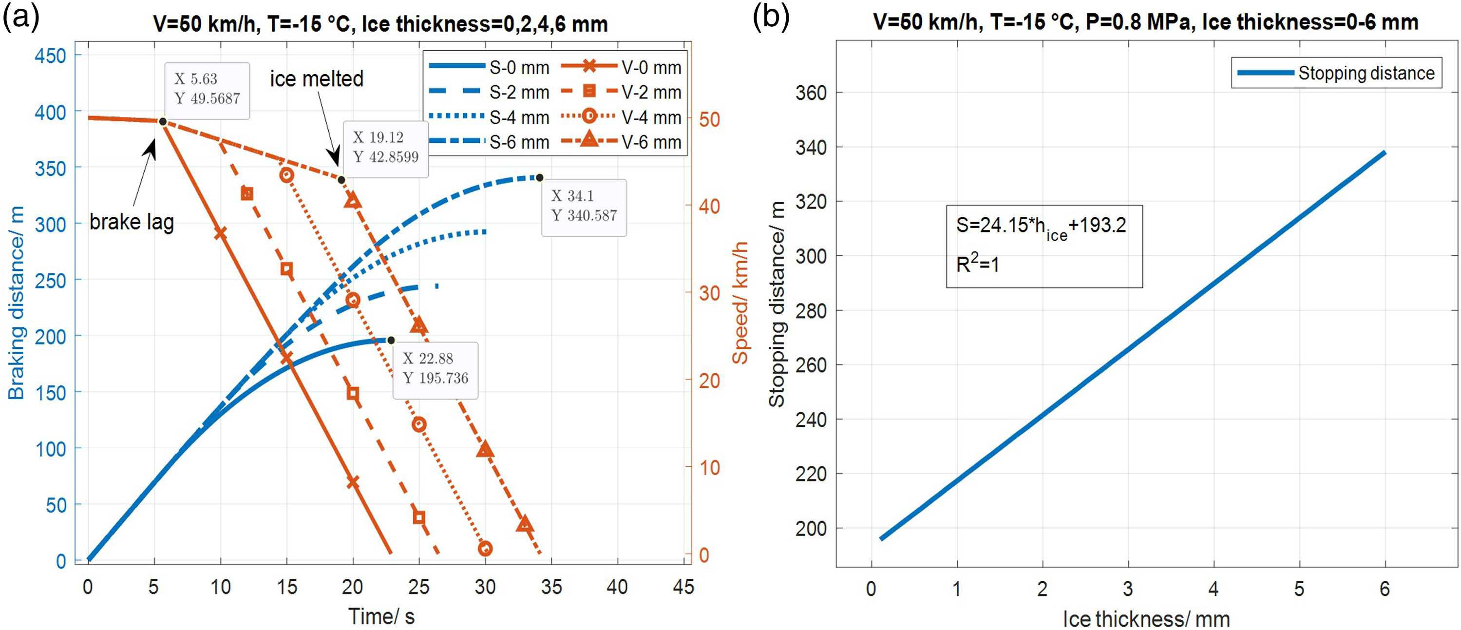
Two field test findings in the literature are in line with the results in this section. One test observed that a low degree of bedded-in blocks seems to help the brake blocks maintain a large friction force. 10 Based on the simulation results, the reason is that slightly bedded-in blocks, i.e. recently fitted brake blocks, do not have much wear and have a small clearance to the wheel. The small clearance limits the maximum thickness of the ice, so the thin ice has little effect on the braking distance. A slack adjuster helps to keep constant clearance but this clearance has a large acceptable tolerance, ±2 mm, 23 and it mainly works for well bedded-in blocks. Mof the time, slightly bedded-in blocks have a small clearance than well bedded-in blocks. An explanation for poor composite braking performance, the second finding from the test 10 is the time delay to fully activate the brake force. The time delay can partly be affected by the time to remove ice, which is also in line with the simulation.
According to this section’s simulation results, two possible measures to keep good braking performance for composite brake blocks are proposed, which are cheap and effective in enhancing the braking performance of composite brake blocks in winter
7
: 1. Reducing the clearance of the wheel and block, which would reduce the maximum possible thickness of the ice. The standard clearance is 5–7 mm and it is mainly due to curve radii. A small curve radius causes flange contact, and the wheel may contact the brake block without braking when negotiating a curve. If the freight trains mainly run on tracks with large radius curves, the clearance should be reduced as much as possible. 2. Activating the brake system to remove ice and snow before arriving at the station. If the train is to keep an acceptable brake ability all the time, the conditioning braking, e.g., practicing braking slightly needs to be applied every 10 min or 15 km.
22
This method, however, consumes a lot of energy. The frequency of the conditioning brake needs further investigation.
The model developed here focuses on how the ice affects the braking performance, however, it is also essential to determine how the ice is built up since it affects the thickness of the ice. Determining how ice is built up needs further studies where ambient temperature, moisture, wind speed, etc., play important roles.
Initial speed
The initial speed is the train speed when braking is activated. Ice on the surface of the block has more impact on low-speed trains because the train generates lower friction heat flux at low speeds than that at high speeds.
As shown in Figure 6(a), for an initial speed of 100 km/h, the stopping distance without ice on the brake block is 627.9 m, while it is 699.1 m with 3 mm ice. The stopping distance thus increases by 11.3%. For the 25 km/h case, the stopping distance increases by 107.4%, from 67.8 m to 140.7 m. With the decrease in initial speed, the relative stopping distance difference is more significant, but for both the 25 and 100 km/h cases, the stopping distances increase by 72 m. The above results prove that a thickness of ice corresponds to a fixed brake distance delay which is invariant to initial speeds. This conclusion is correct when the ice can be totally removed, or in other words, the kinetic energy of the train is larger than the needed thermal energy to remove the ice. The reason for this phenomenon is that the same amount of kinetic energy is required to melt the ice, and this kinetic energy could move the train at the same distance. (a) Braking distance for different initial speeds and ice thicknesses; (b) Instantaneous speeds for different initial speeds.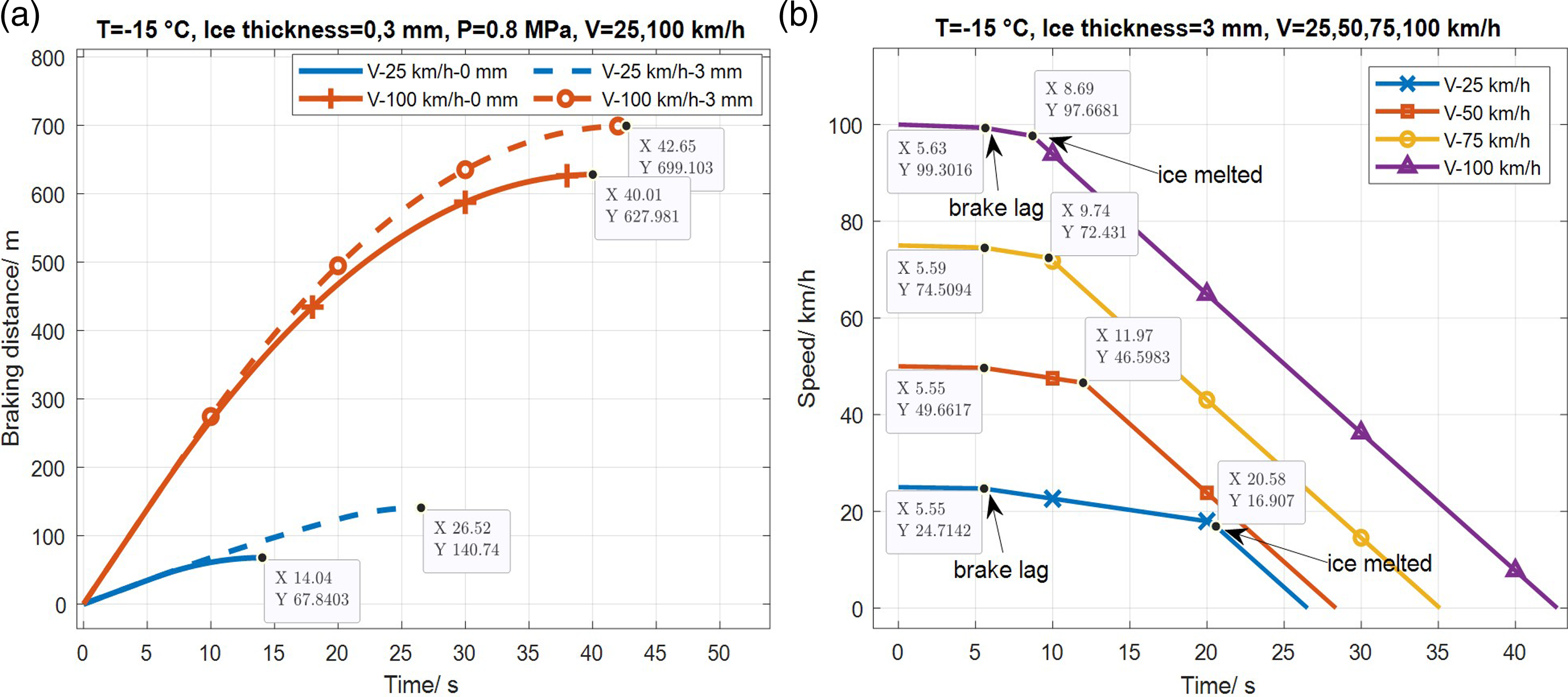
The time to remove the ice for different initial speeds is different because the heat flux depends on the train speed. As shown in Figure 6(b), for the 100 km/h case, the ice removal and COF recovery time is 8.7 s. For the speed of 75 km/h, the ice removal time is 9.8 s. For the initial speeds of 50 km/h and 25 km/h, ice removal times are 11.9 s and 20.3 s, respectively. Compared with the case of 100 km/h, the time to remove the ice for the 75 km/h, 50 km/h and 25 km/h cases increases by 13.3%, 37.0%, and 133.6%, respectively.
The wheel’s high rotational speed contributes to the friction heat. As shown in equation (1), the friction heat flow rate is equal to μFpV. When the speed is high, the friction heat flow rate is large, so more heat transfers to the ice at high train speeds per unit of time. As shown in Figure 7, ice results in differences in the stopping distance with different initial speeds. For 3 mm ice thickness, the ice is removed when the initial speed is higher than 17 km/h, so the wheel is in contact with the brake block before the train stops. In contrast, ice cannot be removed if the initial speed is lower than 17 km/h. The simulation results are consistent with a finding stated in the accident report
7
: accidents mainly happen at low speeds, like 10 km/h, 15 km/h, or during shunting work. The result of this section shows that the train needs more time to remove ice at low speeds. Sometimes, it is even impossible to remove the ice totally before the train stops. Stopping distance for different initial speeds.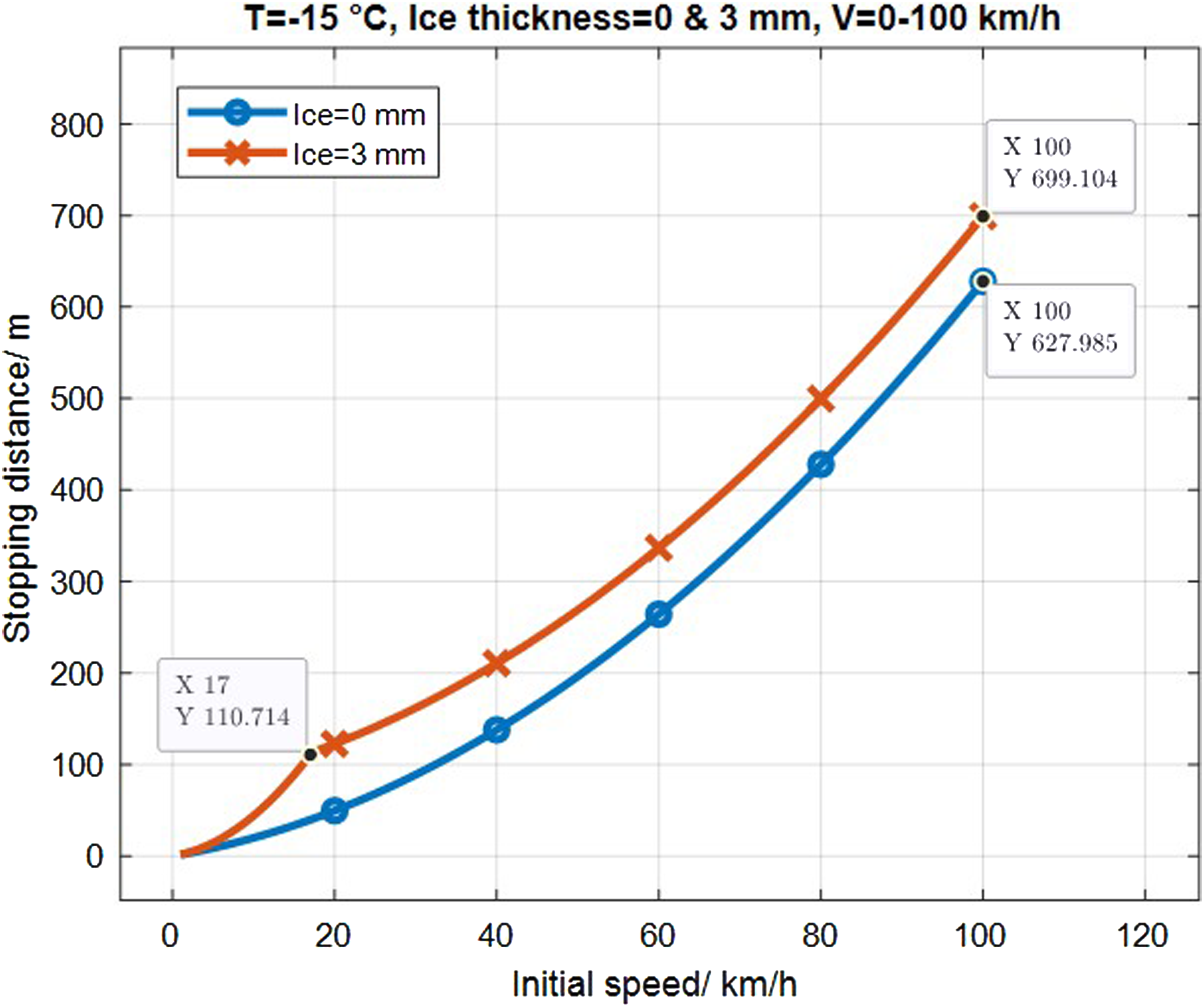
Ambient temperature
Ambient temperature refers to the average temperature of the environment where the train runs. At low ambient temperatures, the compressive strength of ice is high, 16 which implies that much heat is needed to remove the ice from the brake block and the braking distance is long.
As shown in Figure 8(a), the stopping distances vary from 624.6 m to 786.0 m, with ambient temperatures ranging from 0°C to −30°C. Compared with the case at 0°C, the relative stopping distance differences increase by 7.9%, 16.9% and 25.9%. The stopping distance increases because the time to remove ice increases. When the ambient temperature is 0°C, the train has constant retardation after the brake lag because ice is directly removed because of its low compressive strength. Ice does not influence the stopping distance at 0°C. (a) Braking distance and speed for different ambient temperatures; (b) Stopping distance and ambient temperature.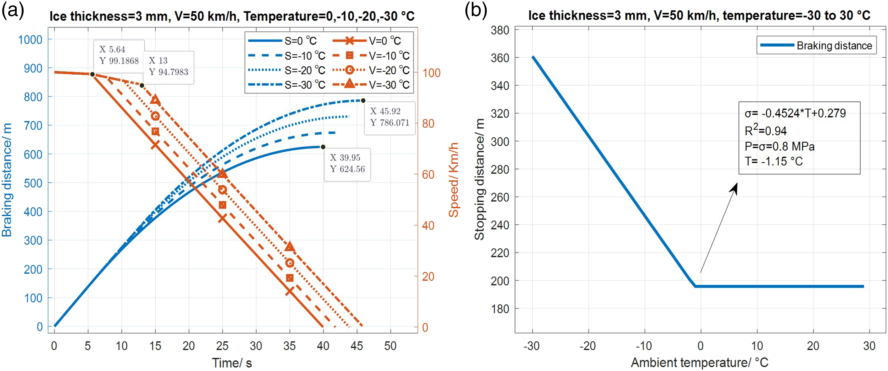
According to reference 16, ice compressive characteristics can be described by equation (3). Once the ambient temperature decreases from 0°C to −10°C and −20°C, ice compressive strength increases from 0.279 MPa to 4.8 MPa and 9.3 MPa, i.e. more friction heat is required to remove the ice. For a two-axle wagon with 3 mm thick ice on each brake block, the mass of ice on the eight brake blocks is 0.64 kg. For ambient temperatures of 0°C, −10°C, −20°C, and −30°C, the needed friction heat is 0 kJ, 11.4 kJ, 22.4 kJ and 37.3 kJ, respectively. High heat demand results in a long time required to remove ice, and a long time with a low COF for braking, so the stopping distance increases. Figure 8(b) shows that the stopping distances increase when the ambient temperature decreases. The ice crush temperature depends on compressive stress from the brake block and ice compressive strength. As shown in Figure 8(b) text, when the ice temperature is −1.15°C, the compressive strength is reduced to the same as the brake compressive stress. So the ice is removed at −1.15°C and does not melt to water. If the applied brake force is larger than 0.8 MPa, the ice falling temperature could be lower than −1.15°C.
Another reported feature 5 is that accidents mainly happen at low ambient temperatures, mostly below −15°C, coinciding with this section’s findings.
Brake pressure
In this section, the relationship between axle load/brake pressure and braking distance is investigated. Brake pressure changes with axle load to provide proper braking force to avoid sliding. The braking distance decreases with the increase of axle load/brake pressure because a large axle load results in a large normal force. Also, large brake pressure generates considerable friction heat.
For the different axle loads, the contact pressures range from 0.14 MPa to 1.25 MPa. In most cases, the contact pressure between the brake block and wheel is 0.8 MPa.5,14 In this section, the brake pressure changes with axle load. The empty wagon’s total mass is 13 tons with a brake pressure of 0.14 MPa. The fully-loaded wagon of case 1 has a total mass of 40 t with 0.8 MPa brake pressure. The fully loaded wagon of case 2 has a 40 t total mass with 1.25 MPa brake pressure.
As shown in Figure 9, the stopping distance is 199.1 m,267.8 m, and 856.9 m for 1.25 MPa, 0.8 MPa and 0.14 MPa, respectively. Compared with the case of 1.25 MPa, the stopping distances for 0.8 MPa and 0.14 MPa are prolonged by 34.3% and 329.7%, respectively. The empty case’s stopping distance is extremely long because of low normal force and low brake pressure. Firstly, the empty wagon’s total mass is 13 t, which results in a lower normal force than for a fully loaded wagon with 40 t. The normal force is equal to mg. The available adhesion force is mgα, where α is the adhesion factor. The larger the mass of the train, the larger the available adhesion force. Secondly, insufficient pressure results in a relatively low force on the contact surface between the wheel and ice, which produces limited friction heat flux. Low friction heat flux requires much time to remove ice. After ice removal, the COF between the wheel and brake block increases, but for the case of 0.14 MPa, the ice is not removed after the train has stopped, which causes the longest stopping distance. The accident report shows that long braking distance accidents often occur with empty freight wagons. The simulation results of this section are in line with this feature. Braking distance and speed with respect to axle load/brake pressure.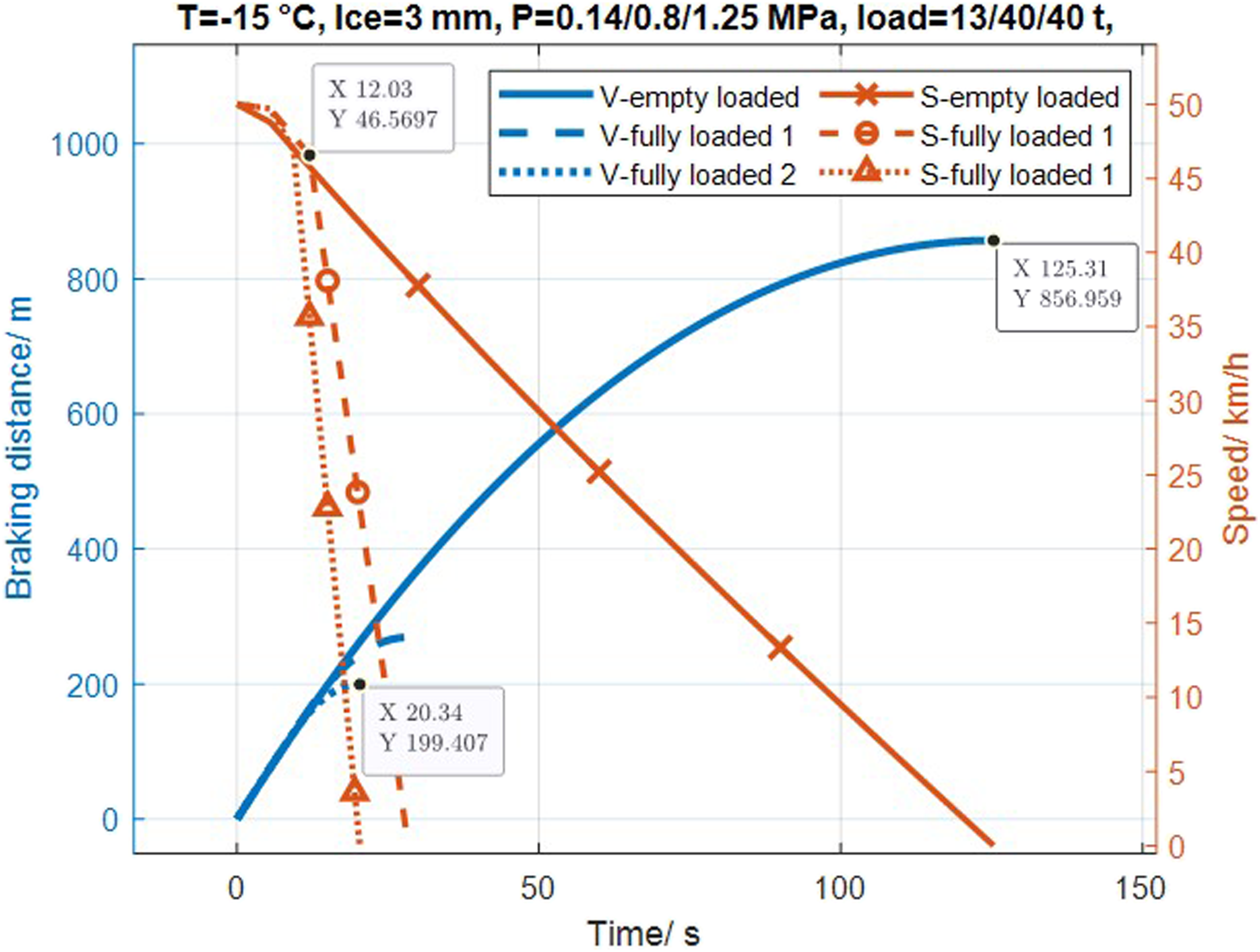
Different ice thicknesses result in longer braking distances for composite brake blocks than for cast iron. Firstly, in Results and Discussion section, it has been shown that ice has a significant influence on the braking distance. The modelled brake blocks are composite material blocks with an average COF equal to 0.2, while cast iron’s average COF is 0.19 according to UIC 544-1. We can conclude that the ice thickness is more important regardless of the materials of the brake block. Secondly, cast iron brake blocks are less prone to build up ice because of poor wettability and water absorptivity than composite materials do.5,8,18 The cast iron brake blocks are made by casting with high density. For the composite material brake blocks (mainly sinter and organic), sinter brake blocks are made by pressing metal powder and other materials, e.g., resin, at high temperatures and high pressure. Organic brake blocks are made by mixing filler materials with a phenolic binder, e.g., resin. Composite brake blocks (both sinter and organic) have good wettability and water absorptivity 5 and therefore are prone to build up ice. 24 In winter, at the same ambient temperature and humidity, the composite material is covered by thicker ice layers and causes longer braking distances. In reference 5, no ice was found on the surface of cast iron blocks, while a layer of ice is often found on the surface of composite brake blocks.
Conclusions
This work studies the influence of composite brake blocks covered with ice on the braking performance of freight wagons in winter. With this model, the relationship between braking distance and the influencing factors, e.g., ice thickness, ambient temperature, initial speed, and brake pressure/axle load, can be studied. The experimental validation of the model is difficult because it is hard to measure some parameters like ice thickness and COF. The results, however, are compared with general findings from test results reported in the literature as much as possible. The following conclusions can be drawn from the presented study: 1. Ice on the brake block’s friction surface significantly influences the braking distance of freight trains. Thick ice, low ambient temperature, low initial speed, empty wagons, or low brake pressure increase the braking distance because more time is needed to remove ice in all these cases. 2. Reducing the clearance between the wheel and brake block helps to enhance the braking performance because the ice thickness is limited by clearance. Conditioning brake also helps to keep good braking performance because ice cannot grow continuously. High brake pressure helps to remove ice fast because it generates high friction heat flux during braking. 3. Cast iron has better braking performance than composite brake blocks in winter because composite materials have higher wettability than cast iron. Ice grows easier on composite brake blocks than on cast iron, which makes a significant difference in ice thickness.
Thus, the presented model provides a method to calculate braking distances of freight trains with ice on brake blocks in winter, and concludes that the wettability of composite material block is the main reason for poor braking performance. Investigating how ice is built up on the surface of brake blocks is important and should be studied in the future. Also, using a dynamometric test rig and modelling more brake pad properties25,26 are necessary to further validate and develop the model.
Footnotes
Declaration of conflicting interests
The author(s) declared no potential conflicts of interest with respect to the research, authorship, and/or publication of this article.
Funding
The author(s) disclosed receipt of the following financial support for the research, authorship, and/or publication of this article: This work is sponsored by the KTH Railway Group, China Scholarship Council and CRRC Zhuzhou. The help of Tore V Vernersson, Chalmers University of Technology, and Yezhe Lyu, Lund University, Aldo Teran Espinoza and Sacha Baclet, KTH Royal Institute of Technology are acknowledged.