
Abstract
Subtle differences in aerodynamic drag, ice friction and sprint start, all influenced by the skill and physique of athletes, determine the descent time and hence competitive success in the sport of Skeleton. A trajectory based simulation was created by parameterising the geometry of the Altenberg Ice Track in Saxony, Germany to find the physically realistic descent time that captures the physics of the aerodynamic drag, ice friction and sprint start. A sensitivity study was used to analyse the influence of each factor on the overall performance down a fixed mid-line trajectory. Comparisons are made to the actual descent times to confirm applicability for a set of male and female sliders. It was found that the combined mass of the athlete and sled should be maximised within the rules, the initial velocity from the push should be as fast as possible, the aerodynamic drag should be optimised for each athlete and the ice friction of the runners reduced to their lowest limit. If each variable is optimum, then the final race standings will depend solely on the skill of the athlete traversing the ice track by finding the ‘best’ trajectory.
Keywords
Introduction
The origins of the winter sport of Skeleton are from down-hill tobogganing in the Swiss Alps in the late 1800s. Originally wooden, the sleds have developed over time to become fully metal structures; it is from here that the sport acquires its name. After a brief appearance at the 1928 and 1948 Winter Olympic Games, the sport was added to the Winter Olympic programme in 2002. 1 The modern sport, with the exception of St. Moritz, is held on artificial ice sliding tracks that adhere to the International Bobsleigh & Skeleton Federation (IBSF) design regulations. With an Olympic medal being won or lost in time margins as small as 0.01 s, marginal gains are of significant importance. 2 The aim of this work is to use a physically realistic descent simulation that captures the physics of the aerodynamic drag, ice friction and sprint start to analyse the influence of each factor on the overall performance down a fixed trajectory. The first two sections give an in-depth consideration of the sport of Skeleton and relevant physics required for the development of a calibrated descent simulation.
The length of the IBSF regulated tracks are between 1200 and 1650 m. As shown in Figure 1, a typical corner will have a track wall, a flat base that runs into an elliptical running section with an overhand upper region to keep the sled in-track should it travel too high. A straight section should be no more than 1.4 m wide with a wall no higher than 1 m. 3 The sled must be designed with two runners with no moving parts, and it must be propelled forward by the force due to the athlete and gravity alone. 2 The competition consists of two heats (four in World Championship and Olympic races) and the final position is determined by the aggregate time. A run comprises two sections: the push-phase, or sprint phase, and the descent-phase. During the push-phase the athlete sprints in a bent-over position before loading their body onto the sled. After the load, the athlete drives down the remainder of the ice track in a prone position: this is the descent-phase. 4
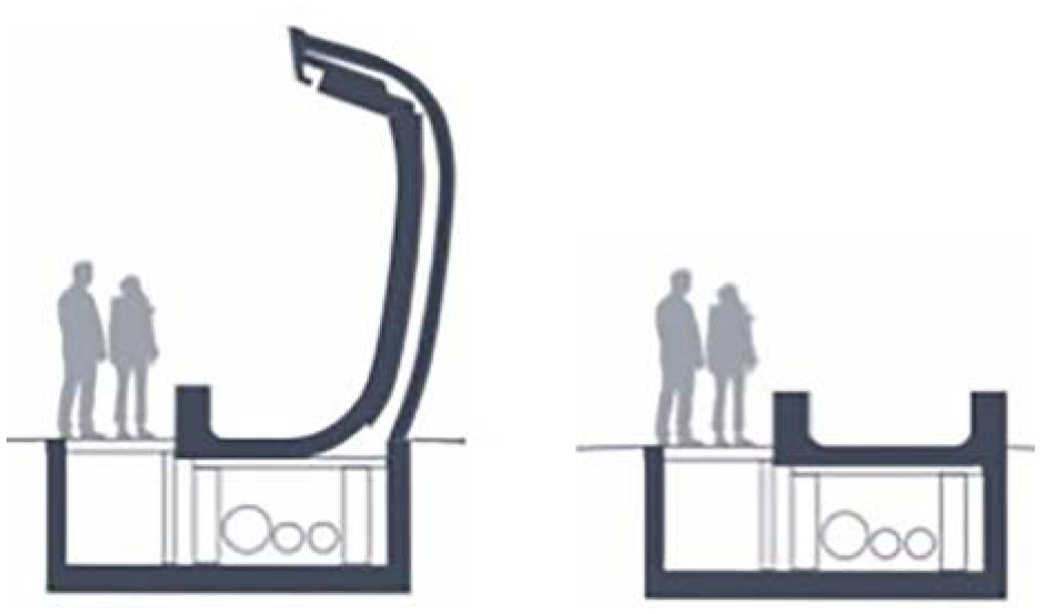
A schematic of a generic ice sliding track design for a corner (left) and straight (right).
Larman et al. 6 investigated data from the 2007 World Championships in St. Moritz and suggested that, isolated from the skill of the athlete, the descent time is influenced by a combination of mass, start velocity, ice friction and aerodynamic drag. Braghin et al. 7 looked at the dynamics of both Bobsleigh and Skeleton. In an ideal scenario and in accordance with the conservation of energy, the potential energy at the top of the track is entirely converted into kinetic energy at the bottom of the track. However, the conversion is not 100% efficient and energy is lost through factors such as drag, friction and driver error (e.g. wall hits). The propulsion force is the force that causes forward motion. In applications such as motorsport, this would be generated by the engine. In both Bobsleigh and Skeleton, the propulsion force is due to gravity. Unlike the ideal case, in the real-world Skeleton system, the influence of mass is not linear and cannot be cancelled from the equations of motion. Braghin demonstrates that a heavier system results in larger gravitational force and faster descent time.
Braghin et al. 7 and Roche et al. 8 developed a simple simulation tool for Skeleton and Bobsleigh respectively. Roche et al. 8 found that while there was a weight advantage in the downhill sections, it was a disadvantage in the uphill sections resulting in a slower overall descent time. Braghin et al. 7 found that reducing the total mass by 10% increased the descent time by 0.311 s.
The effect of start velocity and aerodynamic drag has had a limited study.5,9,10 In contrast, ice friction is an area of much research across many applications. The low friction property of ice is due to the presence of a quasi-liquid layer (QLL).11–14 This acts like a hydrodynamic lubrication and reduces the friction coefficient to below that of a solid–solid contact. 11 As demonstrated by Penny et al., 15 de Koning et al., 16 Poirier 17 and Colbeck, 18 the friction coefficient increases with increasing velocity.15–18 An increase in mass increases the friction force, 19 which will favour a lighter system. Lastly contact patch 20 and surface roughness effect the friction.21–24 Contact patch between the runner and the ice can be altered through geometry optimisation. Reducing the lateral radius is not possible as the IBSF Rules for Skeleton state that the diameter of the runner must be 16 mm. 2 Alternatively, the contact patch can be changed by increasing the bend of the runner through an applied load at one end or by changing the knife design. Surface roughness can be reduced through polishing of the runners ahead of a competition albeit there are specific rules around the polishing process.
Consolidating the research available in the areas that effect Skeleton, this study investigates if it is possible to create a realistic trajectory based simulation model that allows for a sensitivity analysis of the parameters that influence the performance independent of the athlete skill and with available data of a specific track.
Skeleton physics
Equations of motion
For a Skeleton system in one dimensional real space,
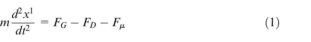
where FG is the gravitational force, FG =mg0sin

In this instance, the curve is analogous to the trajectory, s, of the Altenberg Ice Track in Saxony, Germany. A schematic comparison of these two coordinate systems is shown in Figure 2.
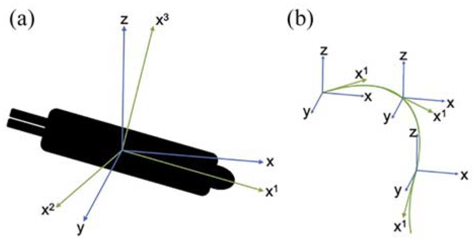
A schematic of the global coordinate system (blue) and the trajectory coordinate system (green) are shown in panel a. The change in relative orientation depends on the curvature of the trajectory with time progression, examples of which are shown in panel b.
The ice friction force, Fµ , for both runners is given by Fµ = µFR, where µ is the friction coefficient and FR is the load. In straight sections FR = FN − FL where FN is the perpendicular component of force due to gravity and given by FN = mgcosθ (see Figure 3), and FL is the force due to aerodynamic lift. However, in banked corners (Figure 4) the centripetal force will also contribute to the normal force. In one dimension, the bank angle is not known, and assuming lift is negligible, this can be estimated via: 25
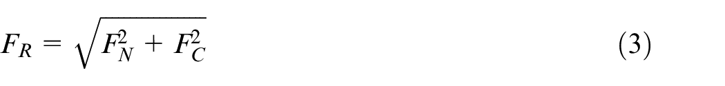
where FC is the centripetal force and given by
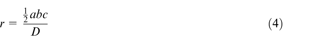
where D = |(
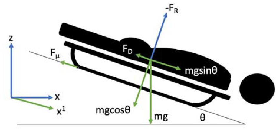
The forces acting upon the Skeleton system in the straight sections of the ice track.
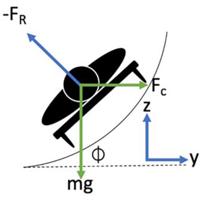
The forces acting upon the Skeleton system in the banked sections of the ice track.
Force due to gravity
The force propelling the athlete forward is that due to gravity. According to Newton’s Second Law, the combined mass of the athlete and sled is the only contributing factor that can be altered in the system.
The optimum physique for a Skeleton athlete has been previously investigated by Roche et al. 8 He looked at the relationship between the height and weight of a Skeleton athlete and their associated descent time. In his simulation, he assumed that a simple scaling rule controlled the relationship between surface area, height and volume. However, the relationship between these two factors for an individual is a complex system of nature and nurture. Inherited genomes and environmental factors (such as diet, exercise and living conditions) will alter the final height and weight of a person. 27 Although en masse a taller person will weigh more (Figure 5), two persons of the same stature but of different body fat percentage and muscle mass will also result in different weights. The effect of the physiology of an athlete is dominant in the sprint start. According to Newton’s Second Law, acceleration is directly proportional to force but inversely proportional to mass hence it would be inferred that there is an inverse relationship between height and sprint performance.28,29 However, a taller stature has shown advantages in both step frequency and length. Therefore, while a tall individual may appear to be heavier and perform better, this may simply be due to more muscle mass from their larger size.10,28 Without a full investigation into the anthropometric data of Skeleton athletes, it is difficult to create a hypothesis relating these factors and their total performance. This paper looks at the total mass (athlete and sled) traversing the track to understand the effect of force due to gravity rather than the body mass of the athlete alone. Therefore, only the variable of mass will be utilised.
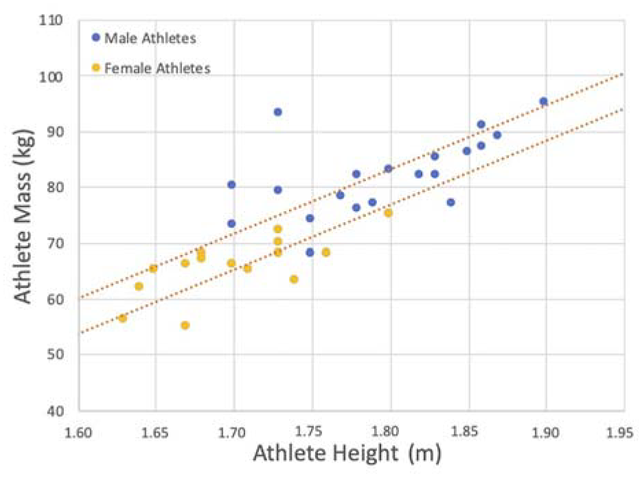
The weight of both male (blue) and female (yellow) Skeleton athletes with respect to their height. 30 The data is overlaid with a 95% confidence interval.
Ice friction
Reviewing equation (1), one of the retarding forces is due to friction and therefore the coefficient of ice friction needs to be known. This has been the topic of considerable research and is difficult to measure for ice. Lozowski et al. 20 and Itagaki et al. 21 created a computational model for a Skeleton runner, which predicts an ice friction coefficient of µ = 0.01. This is the same as the value used by Bromley Technologies as part of the Whistler Sliding Centre Sled Trajectory and Track Construction Study. 31 Therefore, it was decided this constant value would also be used within this model. Further research shows the percentage change in friction coefficient from an unpolished runner to a competition ready runner is approximately 20%. 21 An athlete would never traverse the ice with completely unpolished runners, but Jansons et al.23,24 predicts a 2% difference in friction coefficient between polished and highly polished runners.
The friction force can also be reduced by reducing the mass. This will be inspected but it is not recommended. A 5 kg reduction in mass gives approximately a 4% reduction in friction force.
Aerodynamics
The other retarding force is due to aerodynamic drag. This is calculated via:
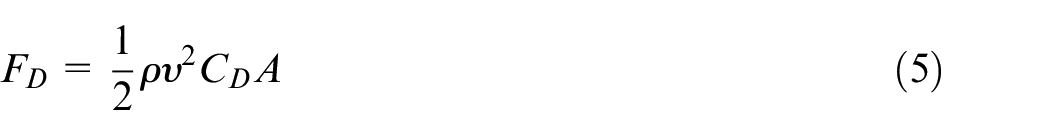
where ρ is the air density, v is the speed of the athlete, CD is the drag coefficient and A is the frontal area. The measurement of aerodynamic drag is sometimes described by the drag-area, or CDA, which is velocity dependent. A study by Brownlie 9 gave an average CDA = (0.056 ± 0.002) m2 for a Skeleton athlete from wind tunnel measurements with a test velocity of 27.78 ms−1 (100 kph). From a BMW test on behalf of the German Bobsleigh, Luge and Skeleton team, a reasonable relationship of CDA with respect to velocity can be determined. 32 The percentage change of CDA relative to the mean value during the simulation is shown in Figure 6. Equation (5) requires the air density to be known to calculate the drag force. The Altenberg track is at a maximum altitude of 760 m, this gives an air density ρ = 1.2 kgm−3 at −2°C. It is assumed there are no cross winds.
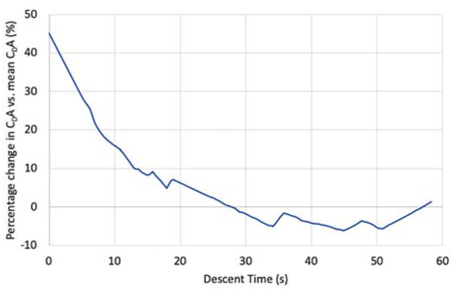
The percentage difference in CDA with respect to the mean CDA to demonstrate the velocity dependence during the simulation descent.
From Brownlie, 9 it is demonstrated that an unoptimised system to a fully optimised system gives a 10% aerodynamic drag benefit. This includes the optimisation of equipment such as the use of a speed suit. If it is assumed that the equipment is already enhanced, then the remaining reduction comes from body position and equates to approximately 5%. 9
Push start
The ‘start’ is measured along a 50 m distance between two timing gates at 15 m and 65 m. However, this is not a measure of only the athlete sprinting on ice. The athlete starts sprinting at 0 m and loads the sled at approximately 30 m. Therefore, the ‘start’ is a measure of part sprint, part load and part slide. Colyer et al. 33 investigated the velocity profile of the Skeleton push-start and the results can be seen in Figure 7. There is an initial acceleration phase before the loading phase, where there is a decrease in velocity. After this velocity drop has occurred the system recovers and continues to accelerate down the ice track. The push-start phase is not modelled; instead, the model begins with a pre-determined velocity at 15 m. To account for the velocity drop, the starting velocity within the model is modified to match the correct velocities measured on ice at the 65 m mark (end of the start). Figure 7 demonstrates the effect of starting the model with the velocity that matches the pre-load or post-load velocity. The former results in a velocity at the 65 m mark that is too slow compared to real world data. Therefore, the starting velocity at 15 m should be modified to match the post-load, and hence 65 m, velocity. In the model, this is checked by having a read-out at the 65 m point and when modifications are made to the start velocity, the change occurs at that point. Looking at the start velocities from the 2020 World Championship held in Altenberg, 2 there is a 3% range. The largest change between two starts for any one athlete is 1.89% and the average is 0.23%.
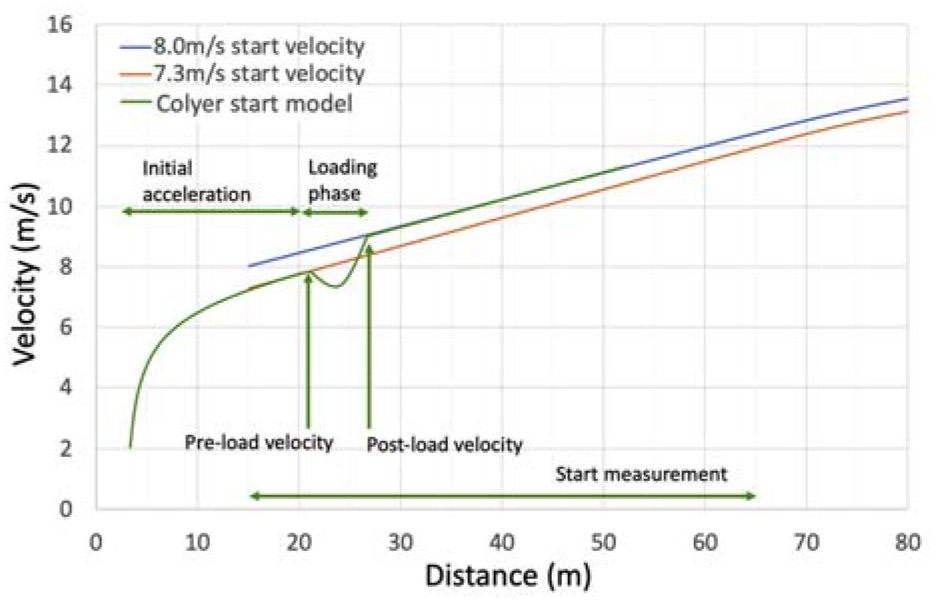
A typical sled velocity profile of a Skeleton push-start (green) as developed by Colyer et al. 33 A comparison of the simulation model with start velocities that match the pre-load (orange), and post-load (blue) velocities are compared to the Colyer model. The former results in a velocity at the 65 m mark that is too slow compared to ice data. Therefore, the starting velocity is modified ahead of the load phase.
Multipliers such as a ‘0.1 s improvement in the start time results in a 0.2 s improvement in the finish time’ are often used as a performance indicator. However, in accordance with Newton’s Second Law (equation (1)), the acceleration has no starting velocity dependence. Therefore, a poor descent can undo any benefit from a fast start. This can be seen in the 2020 Altenberg World Championship results. While in general a faster start results in a faster finish, only 62% of male athletes and 54% of female athletes with a top 10 start resulted in a top 10 finish; of which 27% of male and 28% of female athletes improved on their final position.
A concern of the increase in the weight of the sled is the detriment that it could have on the start time. From Roche, 34 a weight increase of 5 kg could give a maximum 0.5% detriment in start time. It must be noted that the effect of sled weight varies significantly depending on the physical ability of the athlete during the push-start.
Trajectory
The trajectory traversed by a Skeleton athlete is unique not only to each individual but also each run. The optimum path through a corner will even vary depending upon the previous one. For this reason, it becomes a highly complex system. Within the simulation model, a single trajectory is assumed to be traversed. The trajectory was created using video footage from the Altenberg track. 30 The analysis was carried out with three types of trajectories: a high-line, a mid-line and a low-line. Named as such depending upon how high the athlete travels in the corners. Each trajectory has different properties, such as distance travelled and centripetal force. While the absolute values were different, no difference was found in the percentage changes in the sensitivity analysis. Only the mid-line trajectory will be discussed in detail in Section ‘Simulation’.
When the data is analysed against competition data, the different trajectories are accounted for within the uncertainty band. This uncertainty band is the variance in descent time for each athlete from real-world data.
Simulation
Altenberg Track
The Altenberg Track was chosen due to it being the location of the 2020 World Championships. The track has a length of 1413 m, a vertical drop of 122 m and 17 corners (7 left and 10 right).
30
Using satellite imagery and geographic information, it is possible to determine the track size, radius and elevation,
35
as seen in Figure 8. According to Wirth et al.,
36
measurements taken using this method are within 1% (or root-mean-squared error (RMSE)
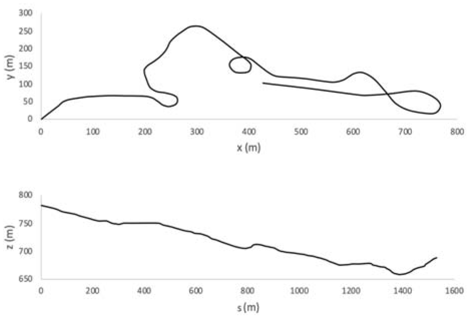
A top-down view of the Altenberg Track (top) and the elevation change during a descent (bottom). The track dimensions were determined using satellite imagery and geographic information.
Simulation code overview
The simulation was developed using MATLAB and a flow diagram of the code used is shown in Figure 9. The constant variables (mass, air density, ice friction coefficient and temperature) are input into the code along with the initial start velocity. The forces due to gravity, ice friction and aerodynamic drag are calculated to solve Newton’s Second Law. Using the parametrisation of the trajectory into x 1 , the equations of motion can be solved to determine the output velocity. If the iteration step number is less than the loop length, the output velocity is returned to the start to repeat the loop again. If the iteration step number is equal to the loop length, the simulation is terminated. The loop length is determined by the number of points used in the track trajectory parameterisation. To validate the data a comparison is made between the simulation results and the real-world ice time deltas as shown in Figure 10. The real-world data is taken from the 2020 World Championship 30 held in Altenberg, Germany and the uncertainty error is the variance in descent time for each athlete in an attempt to account for the effect of trajectory. The line of equality is included in Figure 10 to allow for a correlation comparison. The model is within 2% of the real-world data. The largest variance between runs for any one athlete is 2% and the difference between the fastest and slowest descent time is 5%. As the predictions are independent of precise data such as variance in ice and air temperature during the event, the error of 5% was deemed acceptable.
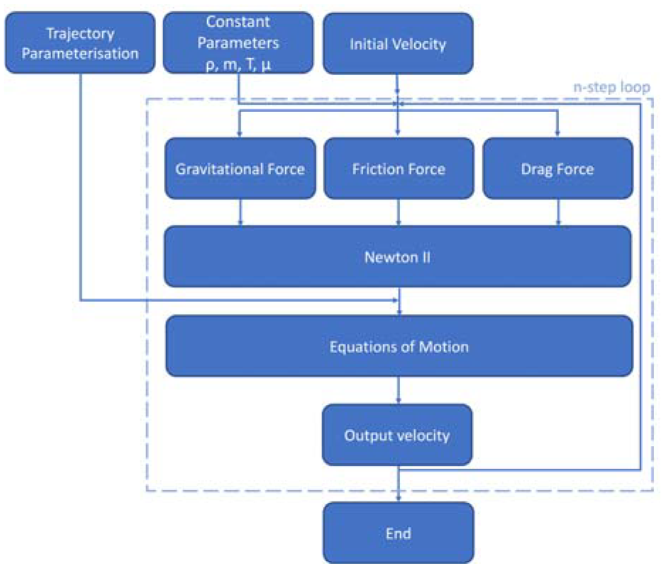
A flow diagram of the code used in the trajectory based simulation.
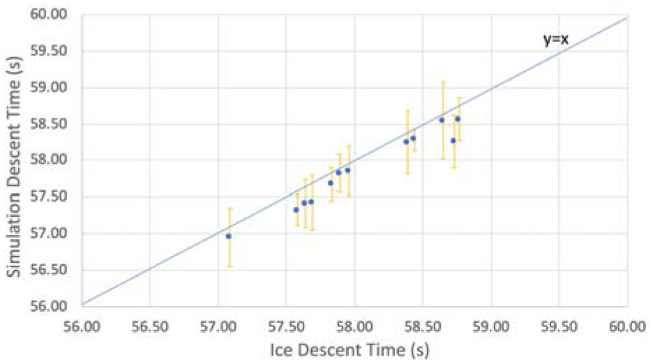
A comparison of the simulation data against the real-world ice data. The error bars are the variance in descent time for each athlete. The line of equality is included in to allow for a correlation comparison.
Sensitivity study
To understand how a variance in each component affects the performance of the athlete, it is necessary to carry out a sensitivity study. As previously stated, these components are friction, mass, aerodynamic drag, starting velocity and trajectory. The effect of different trajectories is outside the scope of this study.
A sensitivity sweep is conducted reducing each component by 5%, 10%, 15% and 20% from a starting condition of combined mass m = 120 kg, starting velocity of 12.5 ms−1 (45 kph) at 50 m, poor aerodynamic form and a runner friction coefficient of µ = 0.01. The results are shown in Figure 11. From the results, both a mass and a start velocity reduction results in an increase in descent time. A reduction in friction coefficient and aerodynamic drag results in a decrease in descent time. The largest changes are seen from a change in start velocity, then ice friction coefficient, then mass and lastly aerodynamic drag. However, a 20% difference in these components may not be possible in reality. Therefore, each component is inspected using the literature to understand the possible improvements and the impact on performance.
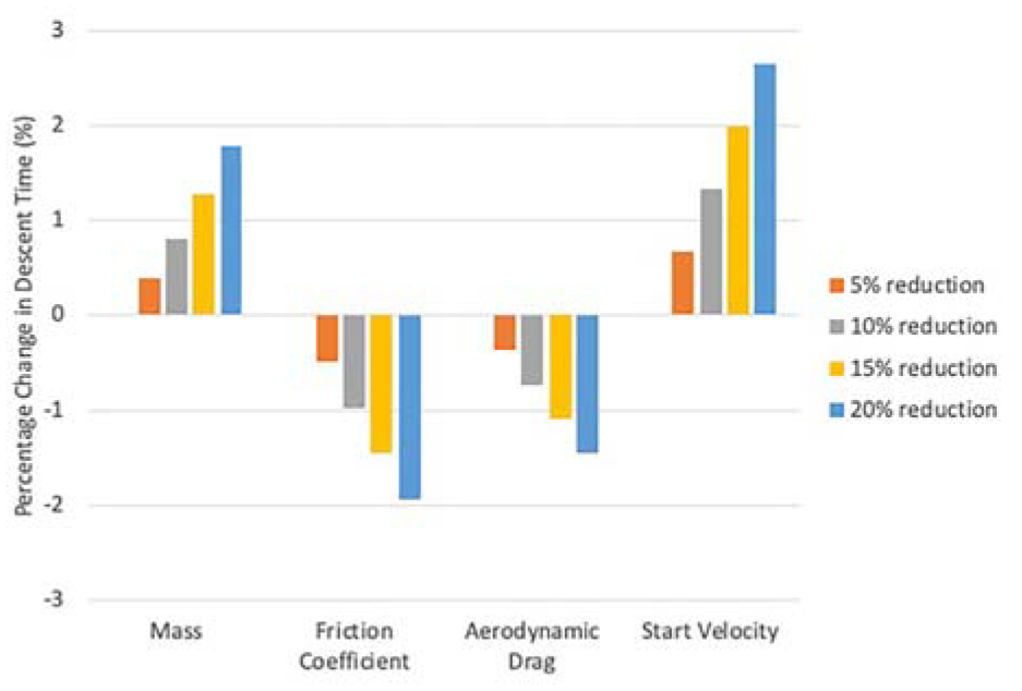
The percentage change in descent time for a 5%, 10%, 15% and 20% reduction in each of the components that affect the descent time. These are the total mass, the runner friction coefficient, the aerodynamic drag and the starting velocity.
Initially considering a male athlete with combined sled and athlete mass m = 115 kg, a starting velocity of 13.3 ms−1(48 kph) at 50 m but with poor aerodynamic form and mediocre polished runners, we can inspect how changing each of the parameters will affect his descent time. The results are shown in Figure 12. By polishing the runners to the highest possible standard, the friction coefficient improves by 2%23,24 and his descent time reduces by 0.01 s. Optimising the best aerodynamic position, the drag component reduces by 5% 9 and his descent time reduces by 0.22 s. Increasing the total mass from 115 kg to the new max limit of 120 kg decreases his descent time by 0.18 s. As mentioned before, it is thought that increasing the sled mass will reduce the start velocity. This increases the descent time by 0.04 s. Lastly, if the athlete does the fastest possible start velocity from the sprint portion of the push, the descent time decreases by 0.15 s. In this example, the largest improvement is seen from optimising the aerodynamic drag, then increasing the mass, followed by increasing the start velocity and lastly reducing the ice friction.
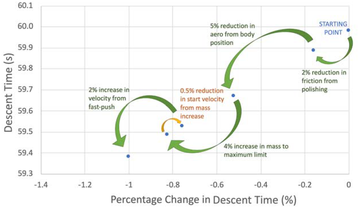
The sensitivity of the Skeleton descent time with respect to a 2% reduction in friction, a 5% reduction in CDA, a 4% increase in mass and a 2% increase in push-start performance. In this scenario, the variable that gives the largest improvement is the aerodynamics, followed by mass increase, push-start and then friction. The percentage improvements are taken from the possible enhancements in each area between two competition runs.
Previously it was stated that the friction force can be reduced by a weight reduction. However, the results in Figure 12 shown that a 5 kg weight increase reduces the descent time by 0.18 s despite the approximately 4% increase in friction force. Therefore, the friction force should be optimised through geometry and adequate polishing and should not be done through mass reduction.
In conclusion, the combined mass of the athlete and sled as well as the start velocity should be the maximum possible. The aerodynamic drag of the athlete and sled should be uniquely optimised and the ice friction of the runner should be reduced to the lowest limit. The priority of these factors will depend on the starting point of each athlete and the available scope for improvement.
Discussion
This sensitivity analysis aligns with the findings of Braghin et al. 7 but not those of Roche et al. 8 Roche finds that an increase in mass is only beneficial when the sled weight is constant and is a disadvantage in the uphill sections. In this paper, in all instances the descent time decreases with an increase in mass. This discrepancy is thought to arise from the methodology used by Roche to approximate the aerodynamic drag. Aerodynamic drag is made up of two factors: skin friction from shear stress at the surface of a body and pressure drag (or form drag) from the pressure distribution around the shape. 37 A Skeleton system is a bluff body and so the dominant contribution is from pressure drag. Therefore, it is more beneficial to control the frontal area rather than the wetted area. 38 In some applications, such as automotive design, it can be advantageous to extend surfaces ahead or aft of the wheels to better control the pressure distribution as well as to delay on-set of flow separation. 39 Conversely extending the surface without changing the form results in an increase in drag from an increase in skin friction. The form drag of an athlete will depend on their shape. For example, rounder shoulders can promote flow reattachment, while large lordosis can encourage flow separation over the gluteal region. The return surface of the sled can aid in controlling the wake, but the exact length and angle will be determined by the over body flow characteristics. Roche notes that increasing the athlete height will increase the skin friction, but he also suggests it will result in a decrease in frontal area for an athlete of constant mass and uniform density. While generalised anthropometric data suggests that an increase in height would result in larger shoulder circumference/buttock circumference and therefore an increase in frontal area, 40 anthropometrics varies with different genetics so without a full study of all Skeleton athletes it is difficult to draw these conclusions. Roche assumes the drag effect related to frontal area only and calculates the drag area with a set CD = 0.38. Investigation in the aerodynamic performance of Canadian Skeleton athletes by Brownlie 9 suggested that, while no conclusions can be drawn for A or CD, a taller, larger athlete tends to have a higher drag area (CDA).
For these reasons, it is preferable to understand sensitivities in isolation of the influence of the athlete. Furthermore, an increase in weight can occur from the sled and be entirely independent of the athlete. When Roche varies only the weight of the athlete, he has the same findings as Braghin and this study. When he includes height, he combines the effect of both mass and aerodynamic drag. He states that with a fixed sled mass, heavier and taller athletes have optimum descent times due to increased mass and reduced frontal area. When the total mass is constant (sled mass varies) Roche states that the lighter, taller athletes have the optimum descent time. Now the mass of the athlete will have no influence on the system as the total is maintained by compensating with the weight of the sled and Roche is observing the effect of a reduction in aerodynamic drag. Interpreting the results from Roche with an understanding of these assumptions, they do match those of this study.
Using this model, it is possible to analyse certain sections of the track, including a downhill into an uphill section. The simulation model was run with a starting velocity of 30 ms−1 (108 kph) into the final corner before the finishing straight for both an 120 kg and 100 kg total mass system. The percentage difference in velocity can be seen in Figure 13(a). The percentage difference at time interval, t, is calculated via:
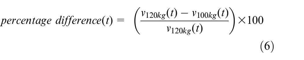
It is possible to carry out the analysis this way as the sled never reaches terminal velocity, which would be approximately 200 kph. As the simulations start with the same velocity, there is initially no difference. However, the percentage change increases throughout the descent with the heavier system finishing with an approximately 1.8% faster final velocity. The relative balance of forces arises from the effective normal force which determined the magnitude of the friction force, the aerodynamic resistance (drag) force and the resolved gravitational acceleration in the direction of travel. The effective normal force arises from a combination of the resolved gravitational and centripetal accelerations. These balances will be fundamentally different in the uphill sections where all forces are acting to slow the sled compared to the downhill sections where only friction and drag act to slow the sled. As the forces depend on mass and speed, the uphill sections cannot be analysed in isolation to the downhill sections. The uphill entry conditions will depend on the behaviour in the previous corners and/or straights of the track.
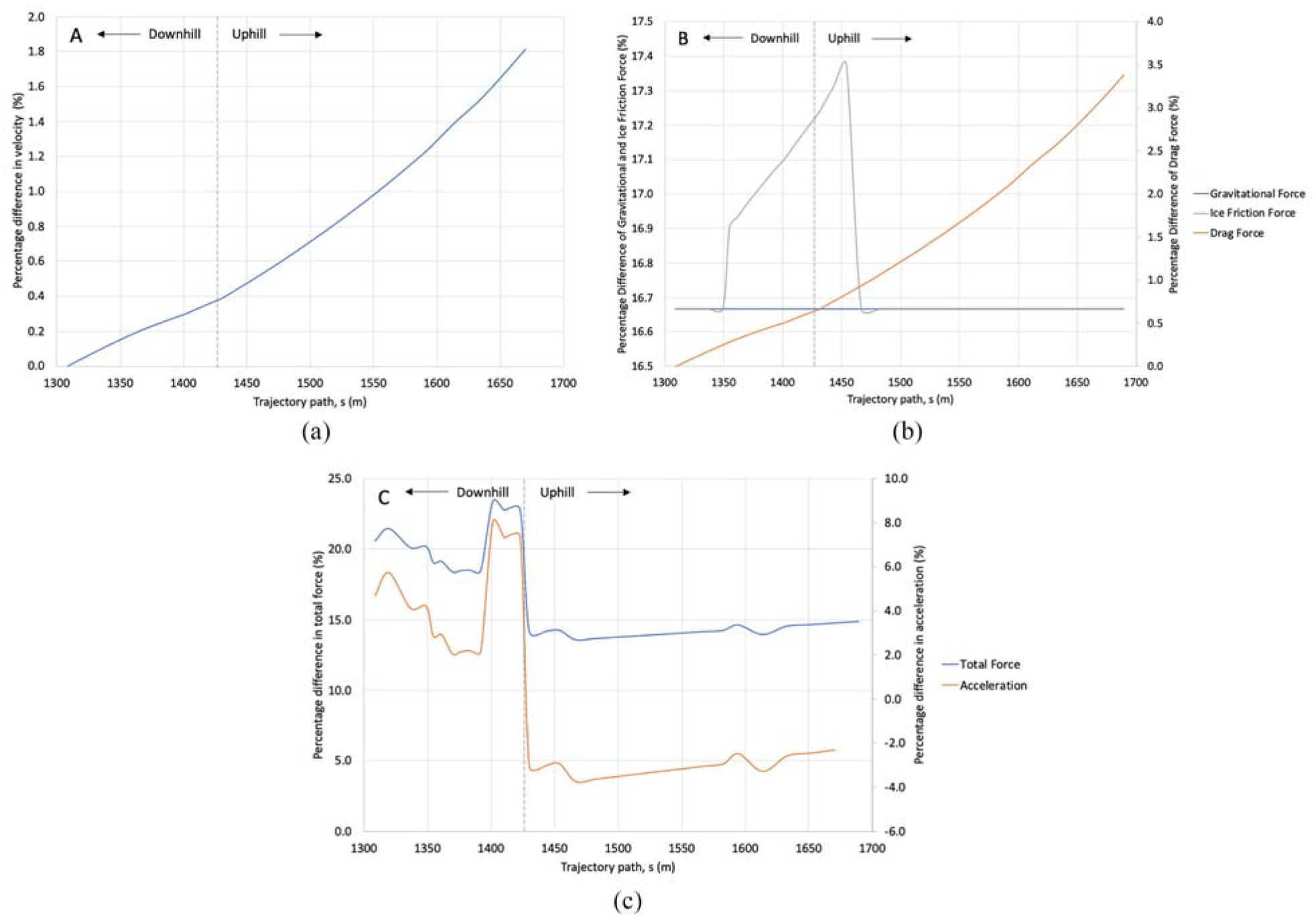
The percentage change in velocity (a), gravitational force, ice friction force and aerodynamic drag force (b), the total force and acceleration (c) between an 120 kg and 100 kg system during a descent of the downhill section into the final corner before the uphill finishing straight.
The results for percentage difference between the gravitational force, the aerodynamic drag force and the ice friction force are shown in Figure 13(b). These are calculated using the same method as shown in equation (6) for velocity. There is a 16.67% increase in total mass between the two simulations. As the gravitational force is linearly dependent upon mass, there is a 16.67% increase throughout the descent. The ice friction force is dependent upon both the normal force and the centripetal force. In the straight section of track, only the normal force component exists resulting in the same 16.67% increase. In the corner, the centripetal component becomes active which has a linear dependency upon mass and a quadratic dependency upon velocity. For this reason, the ice friction force increases to 16.9%, then further increases to a peak of 17.4% with quadratic-like dependency due to the increasing velocity difference with the heavier mass. The aerodynamic drag force has no dependency upon mass, but it does have a quadratic dependency upon velocity. As both simulations start with the same velocity, the percentage difference is zero, but it increases to 3.4% during the descent aligning with the increasing velocity difference.
If the percentage difference in total force is inspected (Figure 13(c)), for a heavier system the force is approximately 20% larger in the downhill sections but approximately 15% larger in the uphill sections where the force is now resisting the motion. This aligns with the hypothesis that being heavier is a benefit in the downhill section but not the uphill sections. Having said that, if this were true then the percentage difference in velocity should not continue to increase throughout the uphill section. When the acceleration is calculated, in accordance with Newton’s Second Law, the total force is divided by the total mass. This results in a larger downhill acceleration but a smaller uphill deceleration. This explains why the percentage difference in velocity continues to increase and suggests it is beneficial to be heavier in both the downhill and uphill sections of the track. Furthermore, this result should be applicable for all three sliding sports: Skeleton, Luge and Bobsleigh.
Conclusion
This study aimed to develop a physically realistic descent simulation model that captures the physics of aerodynamic drag, ice friction and start velocity. Consolidation of existing research has allowed for the development of such a model. This provided a platform for in-depth analysis of the different factors that affect the Skeleton descent independent of the athlete’s skill.
The model allowed for analysis of the interplay of factors for example weight and aerodynamic drag. It was possible to disentangle why a combination of factors gives one result (a change in athlete mass with a changing sled weight and lower drag), while a change in individual factors yield another (a change in athlete mass or a lower drag only). This in-depth analysis is an industry first and the results are thought to be applicable for all three sliding sports: Skeleton, Luge and Bobsleigh.
Subsequently, it was possible to carry out a sensitivity analysis to determine the best set-up of an athlete and their equipment. This sensitivity study has demonstrated which areas give the most benefit as well as areas of optimisation that should or should not be done if they have a detriment elsewhere. In summary, the following have been determined: the combined mass of the athlete and sled should be the maximum allowed value to maximise the downhill acceleration despite the slight degradation to friction and start time; a fast-push from an athlete will result in a faster start velocity and therefore descent time; the drag area of the athlete and sled should be uniquely optimised to reduce the retarding effect and the athlete should adopt the best aerodynamic body position; and the ice friction of the runners should be reduced to the lowest limit – this should be done through optimum polishing process and should not be done through mass reduction.
Footnotes
Acknowledgements
This work was carried out as part of the doctoral research at the University of Southampton with support from the British Bobsleigh & Skeleton Association and the English Institute of Sport.
Declaration of conflicting interests
The author(s) declared no potential conflicts of interest with respect to the research, authorship, and/or publication of this article.
Funding
The author(s) received no financial support for the research, authorship, and/or publication of this article.