
Abstract
To improve the accuracy of braking distance measurement and reduce the impact of human factors on brake risk assessment of escalators, a non-contact braking distance measuring device based on infrared ranging principle is designed. Futher, a quantifiable risk assessment method of brake based on failure mode and effects analysis (FMEA) is propose in this paper. Characteristics and trends of distance changes during emergency braking process of the escalator are theoretically analyzed. To extract, process, and recognize the distance change signals, and finally to realize accurate measurement of the braking distance, a high-speed infrared distance measurement technology is used. Influencing factors of the escalator brake performance are studied. The risk analysis method based on FMEA is used to analyze its failure mode, failure mechanism, and consequences of the failure. A risk index assessment system is constructed and quantified. The test results show that the measurement error of the device designed is 1.6%, which is 1/6 of the traditional measurement method. The repeated measurement error of the device is 1.4%, which is 1/7 of the traditional measurement method. Application results show that the quantifiable risk assessment method quantifies and assigns the risk level according to the weight, which effectively avoids the inconsistent results caused by human bias. The evaluation results are more scientific and reliable.
Introduction
As a special elevator equipment, escalator is an indispensable means of transportation in large-scale subway station, shopping mall, station, and other crowded public place. The number of elevators (including escalators) is increasing rapidly every year in developing country, especially in areas with rapid economic growth. Although elevator manufacturers have taken many measures to ensure the smooth and safe operation of elevators, the elevator accidents still occur from time to time. Take Mainland China as an example, according to statistics released by China state administration of market supervision, China had 15,2547 million special equipment by the end of 2019. Among them,there were 7,0975 million elevators(including escalator) accounting for 46.53%, as shown in Figure 1.

Classification of China’s special equipment quantity in 2019.
The death rate is declining from 2011 to 2019 in China,as shown in Figure 2. Due to the large cardinality, the casualties caused by elevators still cannot be ignored. There were about 58 elevator accidents every year in China since 2011. The number of elevator (including escalator) accidents in China 1 from 2011 to 2019 is still at a relatively high level, as shown in Figure 3.
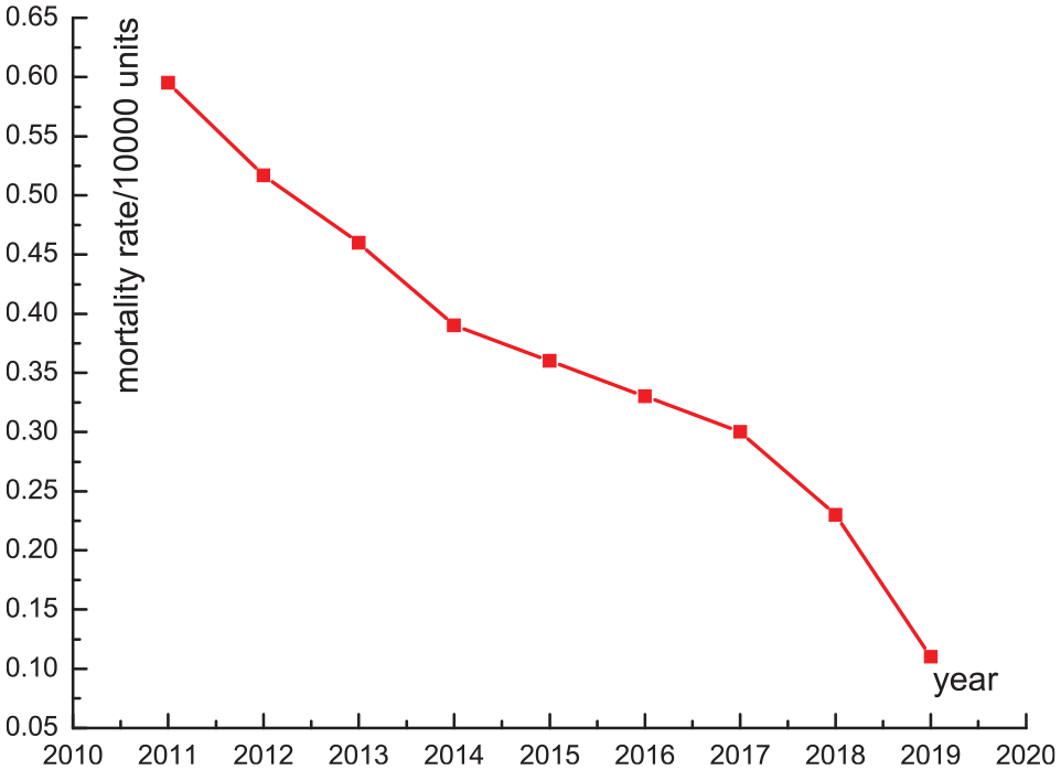
Death rate of 10,000 special equipment in China from 2011 to 2019.

Number of elevator (including escalator) accidents in China from 2011 to 2019.
The main hazards of escalators to people include to get involved, squeezing, falling, cutting, etc. Xing et al. 2 analyzed the causes and consequences of China’s subway escalator-related accidents from 2013 to 2015. Based on the the related factors analysis of China’s escalator accidents, Xie and Liu 3 introduced a combination of the Interpretive Structural Modeling (ISM) and Decision Making Trial and Evaluation Laboratory (DEMATEL) methods. It helps to establish a hierarchical structure of the influencing factors and to distinguish cause factors and effect factors. In order to avoid the occurrence of hazards or reduce the consequences of hazards, escalators are equipped with many safety protection measures, such as missing step protection, step sinking protection, drive chain break protection, comb plate protection, handrail speed deviation protection, overspeed protection, and prevention reversal protection. Li et al. 4 made a failure-rate statistical analysis of the safety protection measures. The failure rate of the step sag protection, the drive chain break protection, the comb plate protection, the speed deviation protection of handrail belt, the overspeed protection, and the reverse rotation protection is respectively 47.9%, 38.4%, 23.3%, 17.8%, 8.2%, and 6.8%.
The main purpose of these protective measures is to trigger the brake action by the final actuator. The brake is used to stop the escalator to prevent further accidents, rather than the protective measure itself. If the brake is unreliable, the above-mentioned protective measures will not achieve the desired effect. It can be seen that the brake plays an important role in the safe operation of the escalator, and the braking distance is the most intuitive indicator of the brake performance. How to accurately measure the braking distance of the escalator and scientifically evaluate the brake performance attracts a large number of researchers.
State-of-the-art research
References5–9 studied the braking distance of escalators. Jiang et al. 5 designed a wireless monitoring system,which can replace the backward manual measurement method for braking distance. Pan 6 analyzed the factors that affect the stopping distance, studied the potential hazards, and proposed an improved method for stopping distance testing. Hu 7 established a mathematical model based on the actual braking distance of the escalator, without considering the internal structure of the escalator. Liu 8 analyzed the calculation of the escalator braking distance by its established calculation formulas, which can provide theoretical basis for reference. Li et al. 9 studied the relationship between the braking distance and the load of escalator, realized the prediction of the braking distance with little load. Reference10–14 studied the braking performance. Park and Gschwendtner 10 proposed an efficient multibody dynamics simulation modeling approach that considers the dynamic effects of a step band, handrail band, and passenger traffic load. Kobayashi et al. 11 verified the braking effect of the elevator during emergency braking through experiments. Rogova and Lodewijks 12 analyzed the characteristics of the brake system, and put forward the redundancy requirements for the brake system. Park and Gschwendtner 10 analyzed the braking performance of an escalator using multibody dynamics simulation technology. Zhou et al. 13 made a hazard analysis for escalator emergency braking system based on STAM.
The detection of escalator braking distance reflects the escalator braking performance to a certain extent. However, it is not easy to quantify the safety of escalator brakes since there are too many affecting factors,such as the braking distance, the functional reliability of the brake spring, the wear of the brake shoe, the insulation resistance of the solenoid coil, the temperature rise of the coil.Therefore, the multi-parameter detection and integration method is proposed to help forming a scientific assessment method and improving the safety level of escalators. Through the risk assessment method based on relevant safety theory, technicians can identify the cause of failure and potential hazard effectively. This helps the technicians to take timely safety precautions to avoid accidents.
Risk assessment technology was first proposed in the insurance industry of the United States in the 1930s. In recent years, this method has been widely used in the risk assessment of special equipment.15–18 Developed countries such as Europe and America have started to promote the application of risk assessment theory in elevator management in 1970s. 19 In 2004, ISO 20 published ISO/TS 22559-1 “safety requirements for elevators – Part 1 – global basic safety requirements,” which unified the assessment procedures for elevator safety. In 2006, ISO/TS 14798 21 “methods for risk assessment and reduction of elevators, escalators and moving walks” was published, which established unified principles and procedures for escalator safety assessment.
Although China’s research in this field started late, because of China’s huge application needs, it has also developed rapidly in recent years.22,23 As early as 2007, AQSIQ24,25 issued the standard GB/T 20900-2007, which stipulated the basic principles and procedures of risk assessment and determined the assessment method of risk level. Reference26–32 studied the risk assessment method of escalators. Among them, references26,28,31 analyzed from the perspective of evaluation indicators and references27,29,30,32 studied from the perspective of failure. Hu et al. 26 established a comprehensive safety assessment index system from four aspects of “equipment, passenger, using environment and safety management.” Tu et al. 27 made statistics and analysis on the accident and failure data of domestic escalators in recent years. Yang 28 proposed a dynamic elevator safety assessment mechanism using big data and cloud computing technology. Li and Liang 29 studied the damage modes and their causes of the in-service escalator drive chain, such as surface wear and early micro cracks. Sun et al. 30 put forward the risk prevention and control measures for escalator safety accidents through sorting out and statistics of 110 typical cases. Wu 31 adopted LEC risk assessment method to assess the risk of escalator safety accidents. Hui et al. 32 used FMECA method to analyze the impact of different faults of main parts of driving host on escalator operation, providing effective basis for reliability design of driving host in R & D stage.
The classical assessment methods mostly have their emphases and application fields, it is necessary to choose an effective evaluation method according to the specific application situation. Some assessment methods are easy to operate with several simple steps, but their development is restricted by the lack of theoretical basis. The Failure-mode-and-effect-analysis (FMEA) method was first developed as a formal design method by the aerospace industry in the 1960s, which has obvious reliability and safety requirements. It has been widely used to help ensure the safety and reliability of products, and widely used in various industries, especially in aerospace, automobile, nuclear energy, and biomedical industries.33–39
As a preventive measure tool, the main purpose of FMEA method is to find and evaluate the potential failure and its consequences in the product or process. Measures to avoid or reduce the potential failure occurrence is found to constantly improve it, so that the equipment can get targeted predictive protection and effective reliability.40,41
The steps of FMEA method are shown in Figure 4. This is consistent with the concept of risk assessment of escalator brake. As an important protective device for the escalator safety, the brake preventive measures in advance it is more significant than finding out the cause after the accident. Because the risk assessment method of FMEA is mainly qualitative and easy to be affected by human beings, this paper proposed a quantifiable FMEA risk assessment method, which can effectively avoid this defect.

FMEA method steps.
In summary,current studies provide important references for the research on the brake of escalator. However, most of the studies focus on the derivation of the relationship between the braking distance and the load of the escalator.There are few studies on how to accurately measure the braking distance and how to scientifically evaluate the brake performance.
Given the importance of braking, this paper will focus on the shortcomings of the traditional braking distance measuring method and the limitations of risk assessment methods. An automatic measuring device of braking distance (MDBD) was designed based on infrared technology. In the braking process, it can measure the position change of the escalator at high speed, recognize the braking time through the calculation model, and achieve the purpose of automatic measurement. Through analysis and research of risk indicators, a quantifiable method of brake risk evaluation based on FMEA is proposed, which makes the evaluation results more scientific and reasonable.
The paper includes five parts. Section 1 is the introduction. In Section 2, the principles and shortcomings of traditional measurement methods are introduced, and an improved measurement device and method of braking distance (MDMBD) are proposed, including hardware design and software design. In Section 3, the principle and procedure of a quantifiable risk assessment method for escalator brake based on FMEA are introduced. Section 4 is the test results. Section 5 is the conclusion.
Research on MDMBD
As an important parameter of FMEA risk assessment method of brake, the accuracy of braking distance is related to the assessment results. At present, the trace method based on manual is widely used in the test process, which is easy to operate and convenient. However, this method is greatly influenced by human factors, with poor repeatability and large measurement error. Another common alternative to get the braking distance is through the test of running speed and the integral operation. It not only has a large cumulative error, but also not accurate for the acquisition of the braking action.42,43 To solve the above problems, this paper proposed a non-contact test method based on infrared technology. It does not have to calculate any intermediate quantity. It can capture the braking action through the distance change and obtain the braking distance by calculation. And the braking distance measuring device is designed to improve the test efficiency and accuracy.
Principle of brake and trace method
As an important part to the safety of escalator, brake has strict reliability requirements. Taking China’s standard GB16899-2011 5.4.2.1.1.1 as an example, it is required that the escalator should be equipped with a braking system. The braking system enables the escalator to have a braking process close to uniform deceleration until it stops, and keeps it stop. The brake is generally installed between the motor and the reducer, so that the braking torque required by the braking process is small, to reduce the size of the brake structure.
When the escalator is running normally, the control system gives an order to energize the electromagnetic coil, as shown in Figure 5. The electromagnet quickly closes under magnetic force. The brake arm overcomes the compression force of the brake spring and opens the brake shoe, so that the brake wheel can rotate freely. In case of emergency, the control system will give an order to make the electromagnetic coil power off. Because of the magnetism loss, electromagnet quickly reset under the compression force of brake spring. The brake shoe holds the brake wheel tightly, and the escalator stops.

Principle of escalator brake.
Once an emergency occurs, the corresponding safety switch will be triggered. The distance from the triggering of the safety switch to the stop of the escalator is the braking distance. It can directly reflect the braking ability and safety level of escalator. GB16899-2011 5.4.2.1 specifies the range of braking distance at different rated speeds. And it takes the detection of braking distance as one of the escalator safety detection items, as shown in Table 1. It can be seen that for escalators with v = 0.5 m/s, the braking distance should be 0.2–1.0 m. The braking distance is too short, which indicates that the braking torque is large and the deceleration is large. That can easily cause passengers to rush out (It’s like a car hits the wall directly). The braking distance is too long, which indicates that the deceleration is small. Because the escalator in a faulty state cannot be stopped as soon as possible, it easy to cause slipping, crushing, shearing, and other accidents.
Range of braking distance.

Excluding endpoint values.
The traditional test method of braking distance is the trace method, as shown in Figure 6.

Trace method principle.
When the mark runs to the intersection line of comb plate and step, the testers press the stop button. And then the escalator stops. The distance between the intersection line and the mark is the braking distance. It can be seen from the test process that the trace method requires the cooperation of human’s eyes and hands. According to ergonomics, there will be a delay of about 0.2 s from the time the human eye receives the signal to the hand responds. For escalators with v = 0.5 m/s, the error of the trace method is about 10%–50%. The error is obviously large. And the stability and repeatability are generally poor compared with that of computers. The various results of each test will seriously affect the judgment of the braking distance.
Design on improved MDBD
Since the current common trace method is characterized by low detection efficiency, high fluctuation of results and low accuracy. This paper will build a closed-loop braking distance detection system of escalator based on infrared technology. It measures the distance between the reference point and the instrument in real time. And it can automatically find the starting point of the brake through the change of distance and achieve the purpose of accurate and automatic measurement.
The principle of infrared measurement distance is shown in Figure 7. The single-chip computer controls the infrared emitting device to emit infrared light, and the infrared light returns to the receiving device after encountering the reflective plate. The running time of infrared during this period is T. And the distance traveled is the speed of infrared C times T. The distance of single trip is S = CT/2, which is the distance between the instrument and the reference point.

Infrared principle of measuring distance.
Hardware design
To measure the braking distance of the escalator quickly and accurately, a measuring device was designed based on infrared technology. The measuring device is constructed by a slave computer and data acquisition part.
The slave computer is the core composition of the measuring device. Its main task is to receive the signal from the infrared sensor LDM41, calculate the position information, and obtain the real-time position signal. The working circuit part includes the power supply, program debugging, data storage, and other functions of the system. The data processing section of the slave computer analyses the signal, makes a logical judgment, and returns it to the master computer after calculation. Bluetooth module completes communication with the master computer. The device cooperates with software to realize parameters setting, mode conversion, start and stop, spot focus, automatic judgment, position calculation, and curve drawing. The data acquisition part is the front end of the measuring device with a general simple function.
In order to further expand the function of the measurement system, a host computer is added to assist the slave computer, as shown in Figure 8. The host computer part completes functions such as program writing, debugging, compilations, data storage, issuing control instructions, and communicating with the measuring device. Because the host computer mainly completes the function of calculation and data analysis, the general industrial computer is selected.

Hardware system design scheme.
Selection of ARM processor
The slave computer needs to be equipped with measurement sensors and other functions, and should be light and flexible, so as to be easy to carry to the measurement site, so the embedded chip ARM is used for future development. The ARM processor uses STM32 series STM32103RC from STMicroelectronics (ST), which is based on the cortex-M3. It combines 32-bit Harvard micro-architecture and system peripherals that execute Thumb-2 instructions. The main frequency can reach 72 MHz and processing speed 1.2 DMIPS/MHz. It has high-speed embedded memory (up to 128 K bytes of Flash and 20 K bytes of SRAM). It contains two 12-bit ADCs, three general-purpose 16-bit timers, one PWM timer, two I2C, two SPI, three USART, one USB, one CAN, etc. The high integration of this processor greatly simplifies the peripheral circuits, enhances the reliability and scalability of the system and reduces the cost of the monitoring system.
Selection of infrared sensor
In the measurement process, the measurement principle based on infrared is used. The distance to be measured is the distance of the laser from the device to the reflected device. Infrared sensor is used to detect the real-time movement of the escalator, so that the corresponding braking distance can be obtained through calculation. According to the measurement requirements of the device for braking distance, the sampling frequency must reach at least 10 Hz. The measurement accuracy of the sensor should be ±5 mm. RS232 interface can be used for communication. In summary, LDM41 from Jenoptik was selected as the infrared sensor of the device.
Design on working circuit of ARM
ARM processor STM32103RC is the core of the braking distance measuring device. All data processing and control functions need to be completed by it. But the ARM cannot work independently. It must have power, clock signal, and reset signal to work properly. The working circuit of the ARM consists of digital power, analog power, reset circuit, debug circuit, and clock oscillation circuit. As shown in Figure 9.
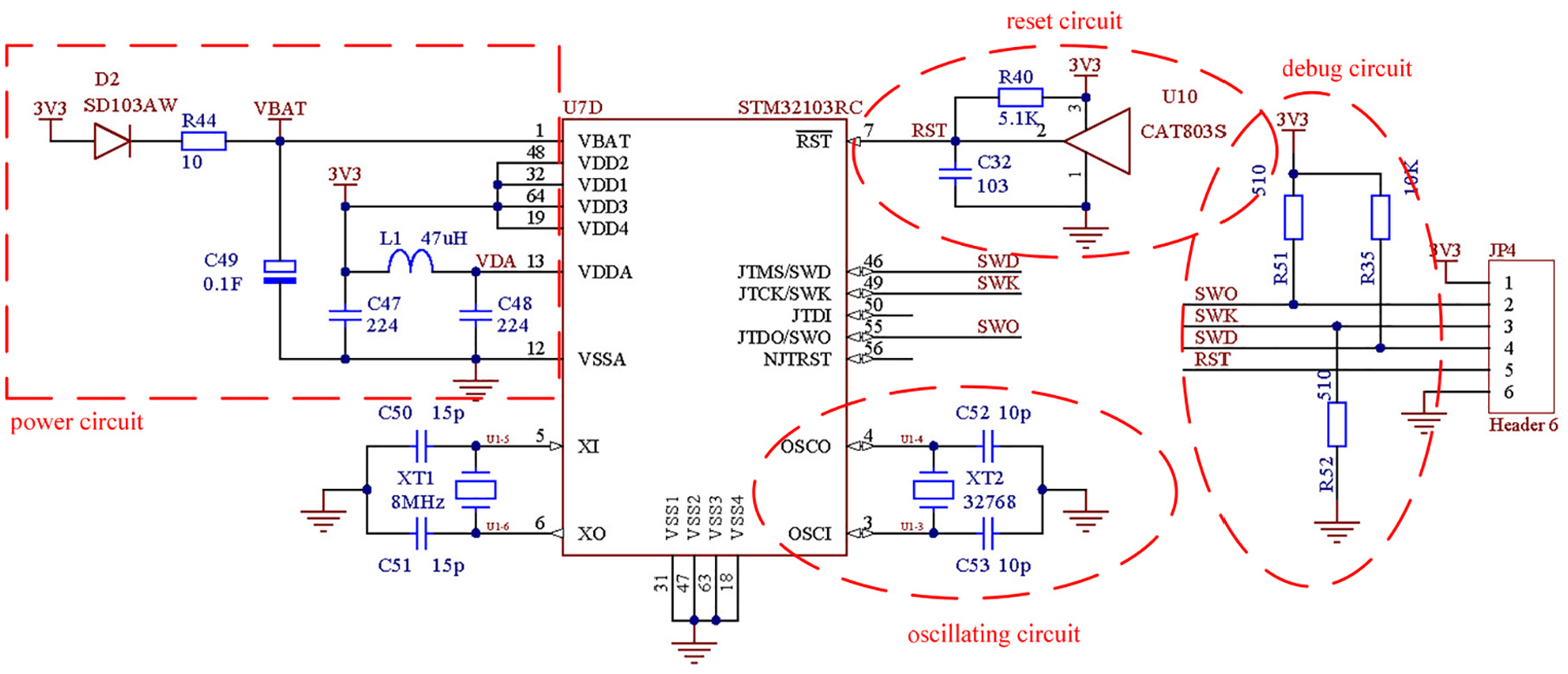
ARM processor working circuit.
The power provides energy for the system, which is the basis of the entire system work. The clock oscillation circuit is used to generate the clock signal in Figure 9. It is the heart of the system. Reset circuit is required to generate a reset signal to initialize the ARM to a certain determination status. The right side of the working circuit is the debugging circuit of the ARM processor. It can debug the program and download the written program to ARM. The working circuit of the ARM enables it to work independently and normally. And it provides necessary preparations for measuring devices to complete the corresponding measurement and control.
Design of position acquisition circuit
As shown in Figure 10, the position signal collected by the infrared sensor LDM41 needs to be transmitted to the ARM processor through the level conversion circuit. The LDM41 is controlled by the ARM processor, through data input signal lines R1X and data output signal line T1X. The position signal collected by LDM41 is input through the R2I port of the MAX232 chip in the form of RS232 level, and is converted to the TTL level and then output from the R2O port to the ARM for processing. The control signal of the ARM is input through the T2I port of the MAX232 chip in the form of TTL level, and is converted to RS232 level, and then output from the T2O port to the LDM41 to implement the control function. Through the MAX232 chip, the level signal conversion between ARM and LDM41 is completed, and the functions of data acquisition and control for the entire braking process are realized.
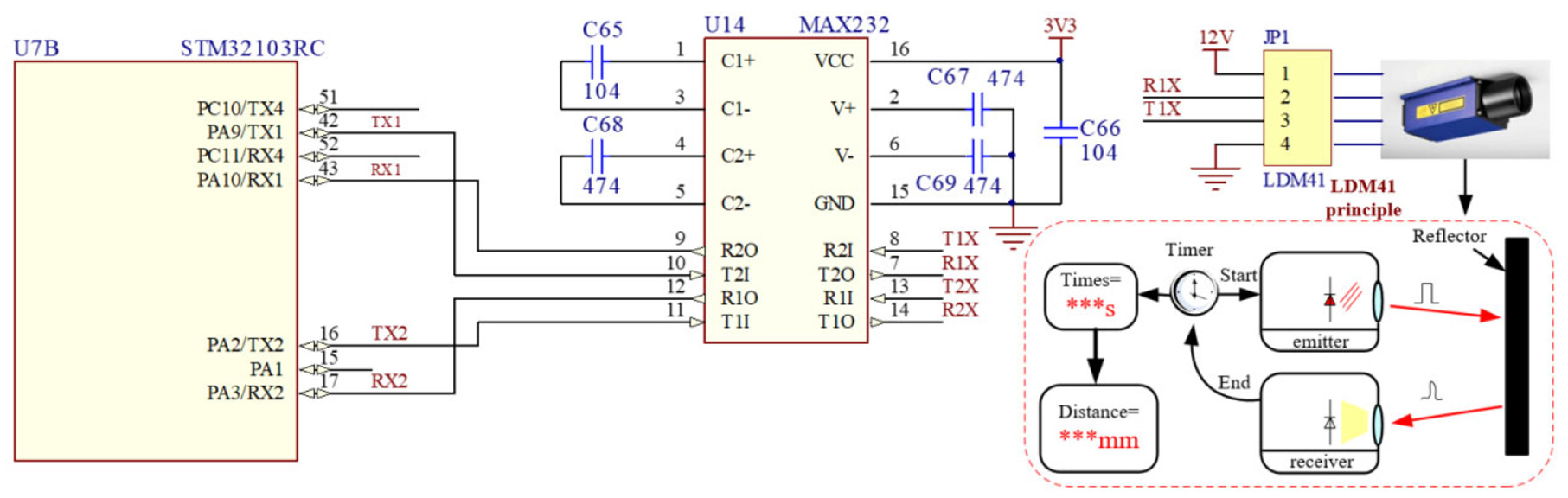
Position acquisition circuit.
The single-row 4-pin chip on the right is used to connect the distance sensor LDM41 in Figure 10. The structure within the dashed box shows the test process of the LDM41. The transmitter is responsible for emitting infrared rays. The receiver is used to receive infrared rays. The timer is used to calculate the time from transmitting infrared to receiving infrared. One half of the time is multiplied by speed of light, and the distance between the transmitter and the reflector is got.
Design of software system
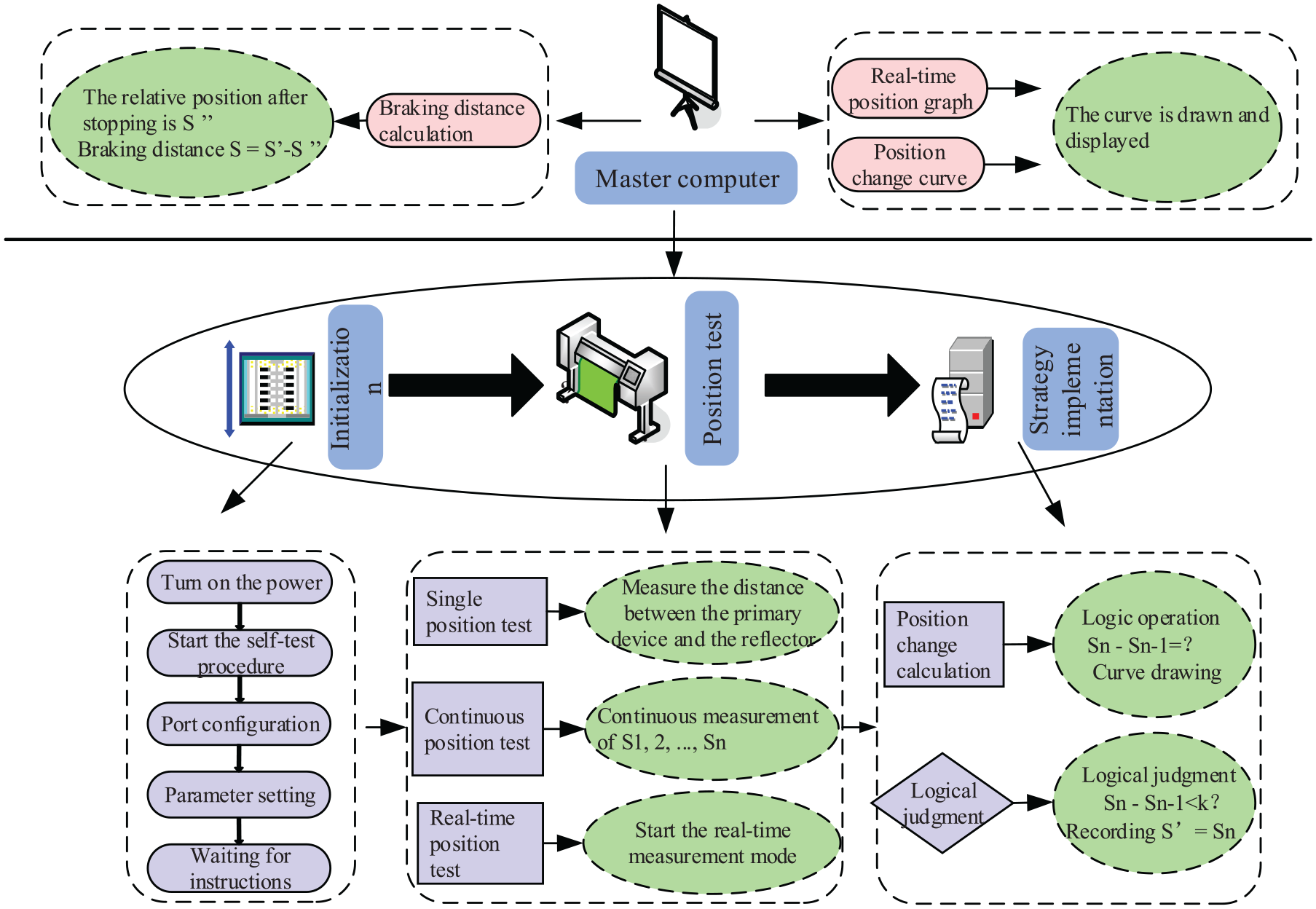
The classical master-and-slaver control mode is used in braking distance measurement system, as shown in Figure 11. In the slave computer, the braking distance measuring device of escalator is the core of the whole system. 44 The software of the device is completed in C language under Keil μvision5 IDE environment. It mainly completes data collection, data storage, transmission, data calculation of position change, logical relationship calculation, and judges the start and end points of the braking. Its specific functions include four parts. The specific content is as follows:
(1) Initialization
Software system.
The ARM has been used as the controller of slave computer. It completes the initialization of the ARM, and the self-test of the functional modules such as registers and counters. According to the specific application scenario, it performs basic configuration of communication port and parameter setting.
(2) Communication function
The slave computer exchanges information through the communication function. On the one hand, the slave computer receives the collected information from the infrared sensor through communication. On the other hand, the important information such as the position of the escalator is also transmitted to the master computer. Then further advanced applications can be done.
(3) Position test
Position test is the main function of the slave computer. It includes single position test, continuous position test, and other functions. If a single test command is sent to the infrared sensor, the single test procedure will be started. Then a test of location information will be completed, and the result will be returned to the master computer. Finally, the relative position of the measuring device will be obtained.
If a continuous test command is sent to the sensor, the sensor will start a continuous test procedure. Real-time test will work at 25 Hz sampling frequency, and the relative positions S1, S2, …, Sn of the measuring device will be recorded and returned to the master computer. During the braking process of the escalator, the position of the measuring device will decelerate near the reflector with the braking force, with the parameter comparison S1 > S2> … > Sn. After the escalator stops running, Sn is a constant value.
(4) Strategy implementation
In the strategy implementation part, the calculation of the position change (Sn − Sn−1) and the logical relationship is completed to determine the starting point for braking. The slave computer obtains the real-time test position information of the measuring device in the continuous test mode. The difference between two consecutive sampling points is Sn − Sn−1. When the escalator moves at a constant speed, |Sn − Sn−1| is a constant value. In an emergency, the escalator brake is activated. The escalator decelerates under the braking force. |Sn − Sn−1| is decreased at constant speed. The first decreasing point is defined as the starting point of the braking, and the relative position of device is recorded as S′ at this time.
The slave computer adopts embedded controller. The development of embedded controller develops fast, but compared with personal computer, the storage and computing functions are still slightly inferior. The slave computer is not specialized in complex computing and good human–machine interface and other advanced application functions. To improve the performance of the braking distance measurement system of escalator, the slave computer transmits the position information to the master computer for further application processing.
The master computer completes the final processing of the data from the slave computer. And the man-machine interaction is also done in the master computer. The main functions of the master computer include:
➢ Changes to thresholds
Different escalators have different speeds and different braking forces, with different deceleration during braking. The difference between the two sampling points is different in real-time testing. The threshold is used to determine the start of the deceleration. A proper threshold value helps to accurately determine the starting point of braking. This threshold can be modified in the master computer program to adapt to different situation.
➢ Data display and graph drawing
This part includes the drawing of real-time position graph and position change graph. The master computer stores the real-time relative position transmitted by the slave computer and draws the curve. The motion trajectory of the measuring device can be visually seen through the real-time position curve, and the relative position of the measuring device can be obtained at any time. Finally, the relative position S″ is got when the escalator stops. At the same time, the position change data from the slave computer is stored and the position change curve is drawn. The changing trend of the position of the measuring device can be seen intuitively, and the inflection point of the position curve and the starting point of the brake can be obtained accurately.
➢ Results display
Through the analysis of the data, the judgment of the starting point and stopping point of the braking, the braking distance is calculated as S = S′ − S″. The result can be displayed in a three-dimensional way, which is convenient for the tester to know the escalator condition directly.
Quantitative risk assessment method
The escalator brake is a safety protection device. It is mainly composed of brake wheel, brake shoe, spring, electromagnetic coil, and other units. Each unit has its own failure mode, and its impact on safety is also different. After studying the structure and characteristics of the escalator brake, a risk assessment index system for escalator brakes is established to prompt the preventive and improvement measures in time.
To provide scientific basis for risk assessment of escalator brakes, a quantified FMEA method is proposed in the paper. The risk assessment process of brake based on FMEA is shown in Figure 12.
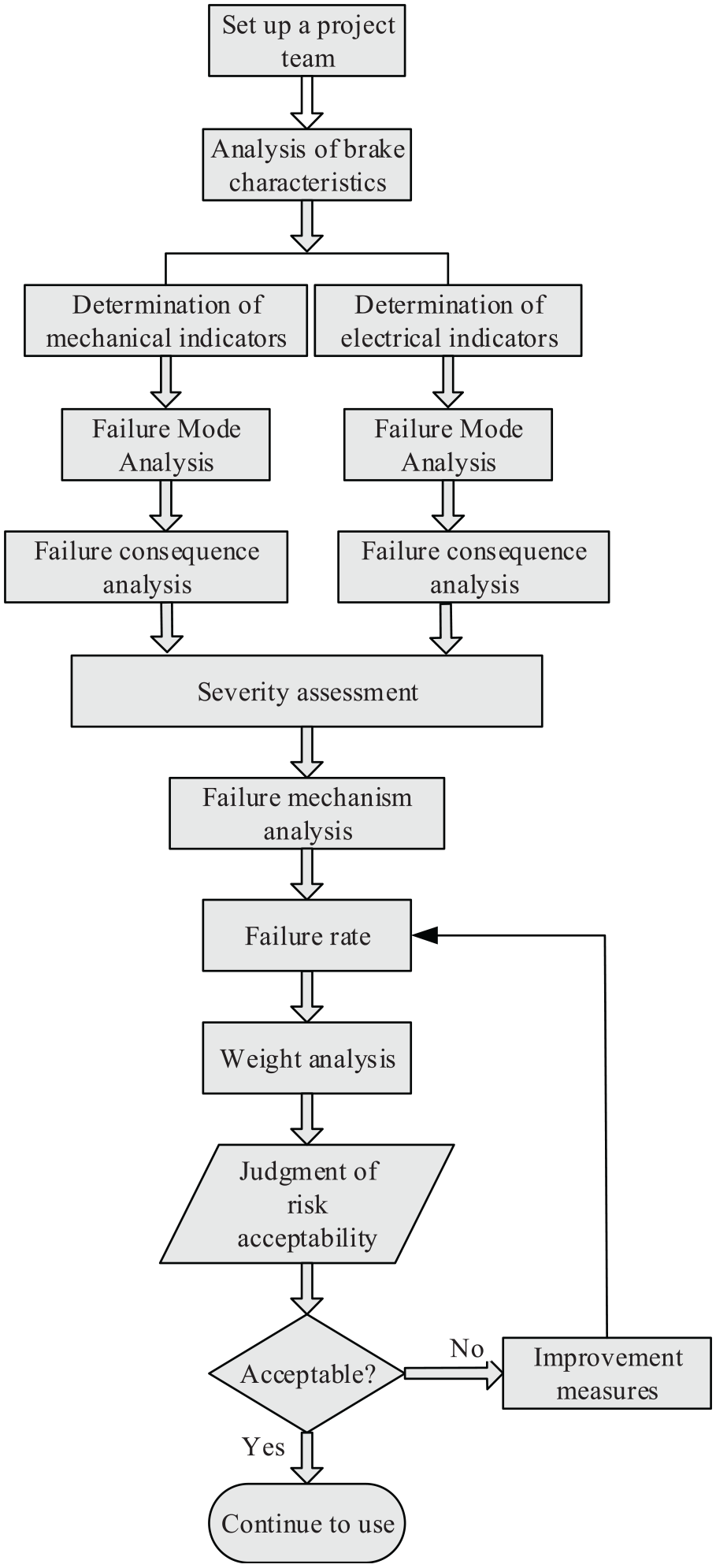
Risk assessment process of brake.
An assessment team need to be established. It consists of three or more industry-experts, and they should have extensive professional skills and experience. The braking characteristics of the escalator are analyzed to determine the mechanical and electrical factors that affect the escalator. And a brake risk assessment index system is formed.
The failure modes and their consequences are studied separately, and the severity of these consequences is evaluated. The failure mechanism of the mechanical and electrical indicators is analyzed. After studying their failure probabilities, the weight of each indicator will be determined. Then, the risk grade of brake is obtained. According to the user’s acceptance of the obtained risk assessment results, corresponding improvement measures are proposed. These measures will ensure escalator brakes operate at an acceptable level of risk.
Brake risk model
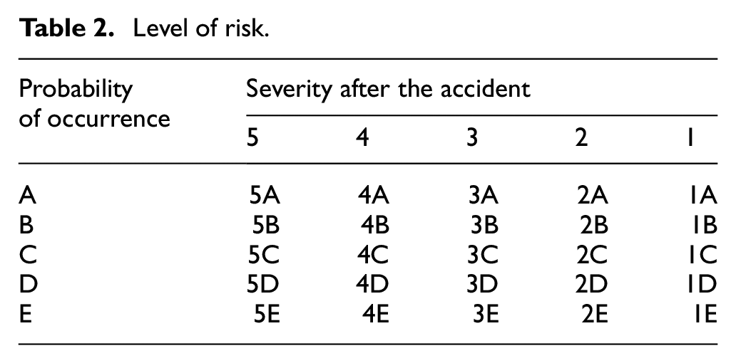
The risk assessment of brake is to analyze the failure mode, failure mechanism, and the consequences of failure of the selected danger index. Risk generally consists of two elements: the possibility of accidents caused by danger (P) and severity of the consequences of the accident (S). R is the risk level. The mathematical model is:

According to the possibility of accidents, it is classified into five levels 31 : A – Very high probability of occurrence, B – High probability of occurrence, C – Higher probability of occurrence, D – Low probability, and E – Impossible to happen. In summary, the classification of indicator risk levels is shown in Table 2.
Level of risk.
Risk assessment index system of brake
One of the main causes for escalator accidents shown by large number of accident cases is the failure of the brake or its design defects. The project team has accumulated a lot of experience in safety inspection of brakes. Combined with the research on brake structure, the construction of brake risk assessment index system is as follows:
Reliable function of brake spring.
Brake wear.
Whether there are scratches on the surface of the brake wheel and the surface of the pad of the brake shoe, high temperature coking particles and oil pollution.
Insulation resistance of electromagnetic coil of brake.
The temperature rising of the coil.
Brake type; Poor if not electromechanical and without additional brakes.
Whether the braking system monitoring device is installed.
Whether the interruption of the brake circuit power supply is achieved by two independent electrical devices.
Braking distance.
Risk quantification
In order to avoid the excessive influence of human factors, the selected indicators are analyzed on their failure modes, failure mechanisms, and the consequences of failure. And the risk of these indicators is quantified. This paper uses a 5-point scale for quantification. If it has the very high probability occurrence with high degree severity (5A), the risk value will be quantified to 5 with the highest risk level. As the severity decreases, so will the corresponding number. The risk level 1E with a value of 0 is almost negligible. The results are shown in Table 3.
Risk quantify.

Risk classification of brake
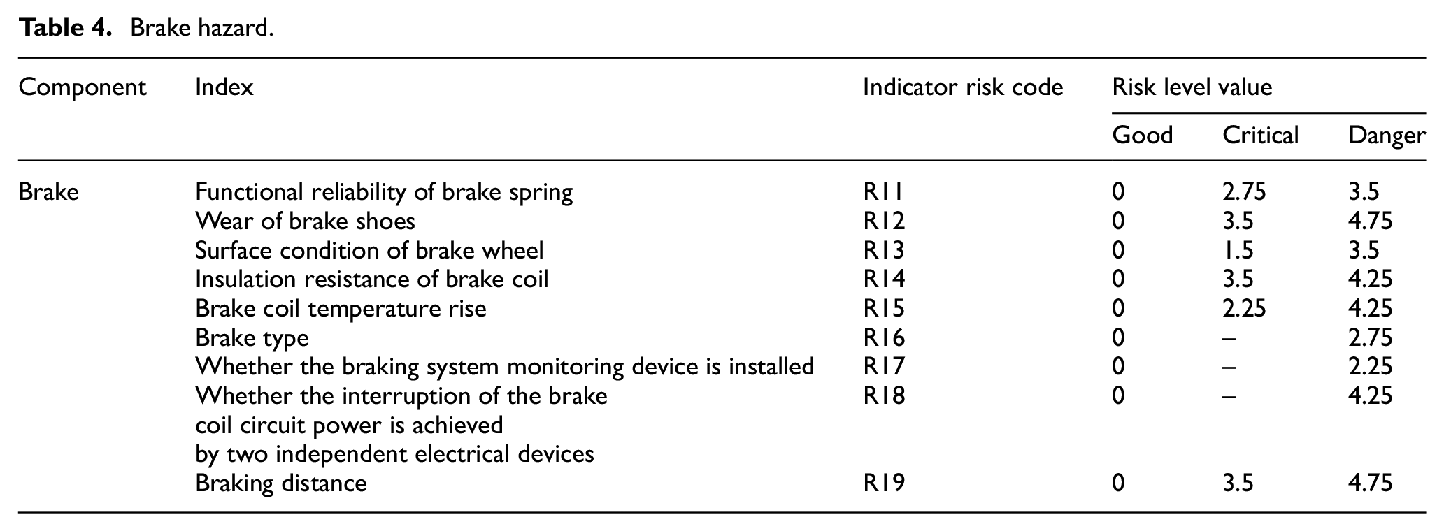
Each index of the brake performance assessment index system constructed in section 3.2 should be analyzed using Formula (1). Taking the braking distance as an example, the index classification can be divided into “good,”“normal,” and “exceeding the standard.” Among them, “good” indicates that the braking distance is 0.2–1.0 m; “exceeding the standard” indicates that the braking distance in rated load is greater than 1.0 m; “normal” indicates that the braking distance in no-load is less than 0.2 m. The above range is for escalator at a speed of 0.5 m/s, for 0.65 m/s, the range is 0.3–1.3 m, and for 0.75 m/s, the range is 0.4–1.5 m. For the weight of a single indicator, it has been expressed by the risk level. For example, the reliability of the brake spring function is obtained through analysis, and the weight is medium, which is represented by risk level 3B. That is, the maximum risk is 3.5. It is known through analysis that the weight of the wear of the brake shoes is large, which is represented by 4A. That is, the maximum risk is 4.75. Similarly, the analysis results of other indicators are shown in Table 4.
Brake hazard.
Since the above analysis has considered the weight of the indicators, the total risk value of brake can be directly added. As shown in equation (2).

The risk classification of brake follows the principles. The cut-off point is half the risk value of all the critical state. When the risk value is less than half of the critical value, the risk level of brake is level two which belongs to slight risk. When the risk value is more than half of the critical state, the risk is level three with moderate risk. When the risk value is greater than the critical value, the risk is level four with great risk. If it exceeds 80% of the total risk value, the risk is level five in a very dangerous state. This paper analyses the risk values through many practical applications comparison and verifies the rationality of the division.
Test results
Test parameters
To verify the designed measuring device of braking distance and the proposed braking risk assessment method, a 6-year escalator was selected for testing. The basic and measured parameters of the escalator are shown in Table 5.
Test parameters.

The distance between the instrument and the reflector is measured in real time during braking. The starting point of braking is determined by the difference between the two measurements. Once the brake signal and stop signal are detected, the measuring device calculates the braking distance. The procedure is illustrated below detailed, as shown in Figure 13.
Place the measuring device on the stopped escalator, power on the device, start the single test mode, and calibrate the position information.
Run the escalator, start the continuous test mode at the same time.
Press the emergency stop button of escalator. When the escalator runs to a uniform speed, the escalator power is disconnected, and the position change information during braking is recorded.
The software analyses data, draws real-time position curve and position change curve, and calculates braking distance.

Scene of test.
Comparison of braking distance test results
According to the test procedure of 4.1, three tests with inflection point respectively 3877 mm/3800 mm/4051 mm were performed on this escalator. The comparison results are shown in Figure 14. The results of position and position change for each test are shown in Figures 15 to 17.

Results of three test: (a) escalator brake, (b) escalator control system, (c) test device designed, and (d) results of three test.
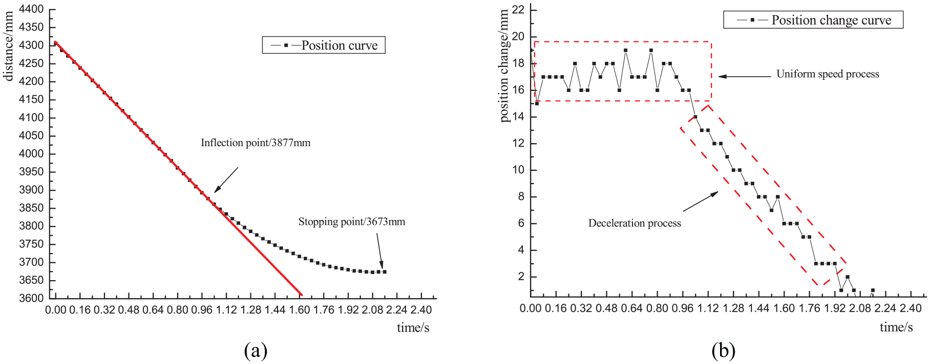
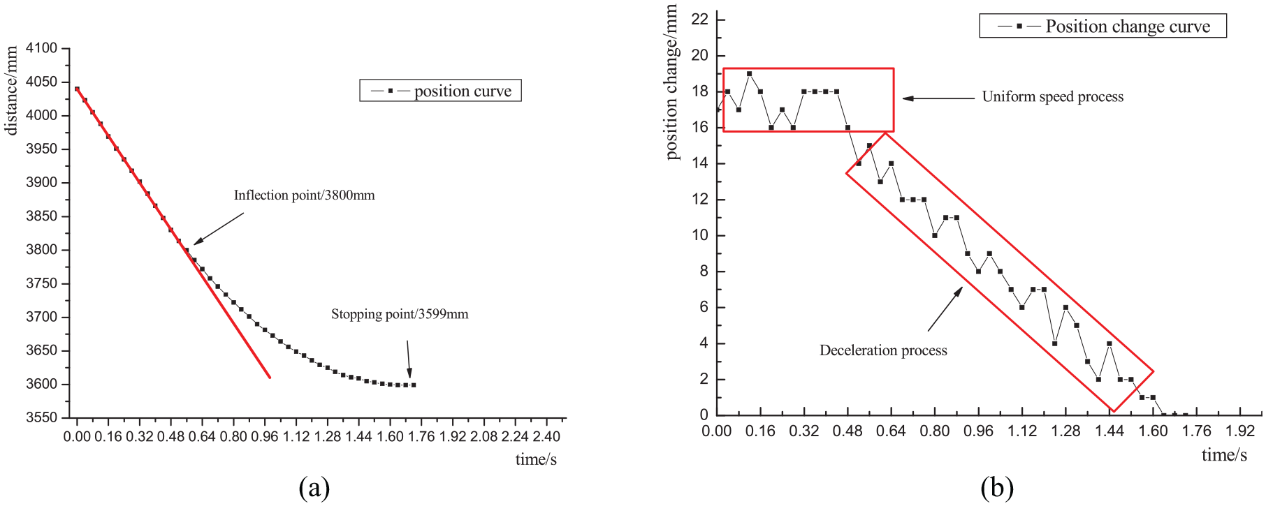
The first test results: (a) position test results and (b) position change test results.
The second test results: (a) position test results and (b) position change test results.
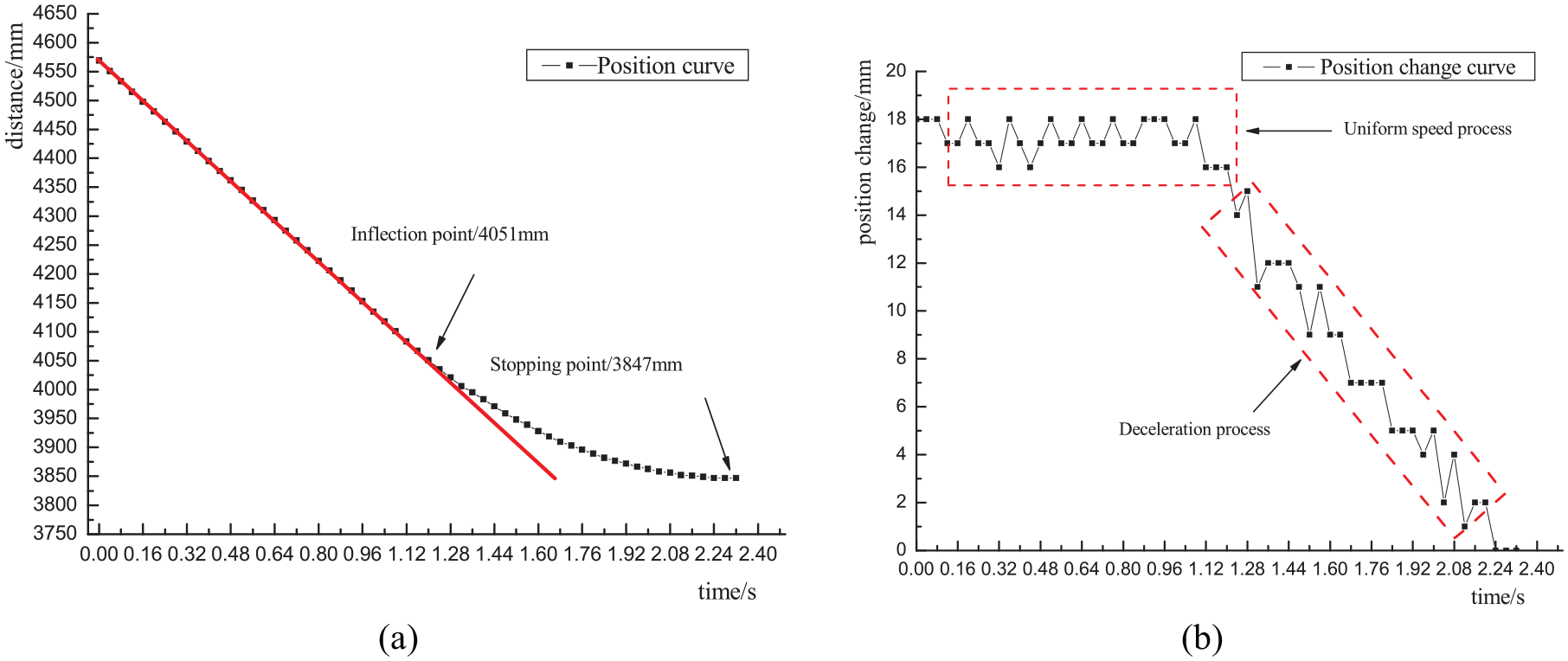
The third test results: (a) position test results and (b) position change test results.
By analysis, the inflection point in the curve (a) is the starting point of the braking in Figures 15 to 17. The escalator decelerates from this point until it stops. It can also be seen from the curve (b) that the escalator runs at a uniform speed before the inflection point. The position curve is a straight line, and the position change curve is approximately horizontal. When the inflection point appears, the position curve changes, and the position change curve slopes downward, indicating that the escalator is braking.
The curve trend of the three tests is basically similar with the above case, as shown in Figure 14. It future proves that the repeatability of the measuring device is better. Figure 15 shows the braking distance measured for the first time is calculated as: 3877 − 3673 = 204 mm. Figure 16 shows the results of the second test, which is calculated as: 3800 − 3599 = 201 mm. Figure 17 shows the results of the third test is calculated as: 4051 − 3847 = 204 mm. On the above calculation, the repeated error of the three tests is only 1.4%. For the traditional method shown in Figure 6, the three results are respectively 0.27, 0.29, and 0.26 m with greater error. Due to the synchronization of human hands and the degree of matching with the eyes during the test, the traditional method is difficult to be precise. The repeated error of the three measurements is as high as 10.3%, which is nearly seven times that of the paper proposed method. Because the traditional method starts from the power failure, the measured error is larger due to the delay influence. The test results of the traditional method and the paper proposed method are shown in Table 6.
Result of braking distance comparison.

If the calculation standards of the two methods are unified, the braking distance result of the measuring device designed should consider the effect of delay. The distance generated by the delay is 0.8 mm × 0.5 mm = 40 mm, and the results are shown in Table 7.
Result of braking distance error.
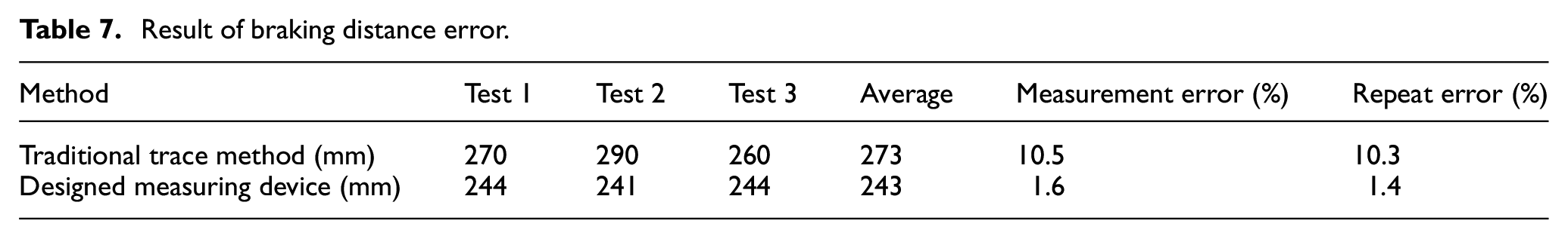
As shown in Table 7, the error of paper proposed method is smaller than the traditional test methods. Moreover, the paper proposed method is simple and convenient. The measurement process of this method is completed automatically, avoiding the low efficiency problem caused by too much manual participation.
Risk assessment results of the brake
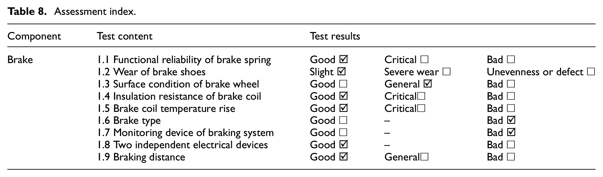
After the measuring of braking distance, each index in the assessment system is tested and analyzed. The results are shown in Table 8. The risk of the brake of escalator is evaluated. And the risk level of the brake is obtained.
Assessment index.
From Table 3 and Formula (2),
Risk level of brake.

Conclusion
The brake is an important safety component of the escalator. Braking distance is a key parameter to characterize the performance of the escalator braking. This paper analyses the shortcomings of traditional escalator braking distance detection methods and the limitations of braking risk assessment methods. The paper further proposes improvement measures from two aspects of distance detection system and assessment method.
In the aspect of distance detection system, a non-contact measuring device of braking distance based on infrared technology was designed, where the hardware structure and software flow were detailed described. In the aspect of assessment method, a quantifiable risk assessment method of brake is proposed, combined with the classification of mechanical and electrical indicators for brake. The main conclusions are as follows:
The designed measuring device captures the position change during the braking process. This can determine the starting point of the braking and reduce the error caused by human factors. The repeated measurement error is 1.4%, while the repeated measurement error of traditional methods exceeds 10%.
The test value of the braking distance is calculated from when the brake is actuated. If it starts from the power-off, the influence of the delay time needs to be considered.
A quantifiable FMEA risk assessment method of brake is proposed. Inconsistent results caused by human bias are effectively avoided. The assessment results are more scientific and reliable.
The weight of the indicator has been considered in the risk analysis stage. It is not necessary to repeat the calculation when calculating the total risk value. The model is simplified. And the indicator flexibility is increased.
Footnotes
Handling Editor: James Baldwin
Declaration of conflicting interests
The author(s) declared no potential conflicts of interest with respect to the research, authorship, and/or publication of this article.
Funding
The author(s) disclosed receipt of the following financial support for the research, authorship, and/or publication of this article: This research was funded by Guangzhou Market Supervision Administration, China: NO. 2020kj26, and by outstanding youth teacher project by Guangzhou College of South China University of Technology: NO. JQ18000188, and by Doctoral Research Startup Project of Guangdong Natural Science, Grant Number 2017A0303102.