
Abstract
Before a new type of railway sleeper can be used in track, standardised laboratory tests must be carried out to determine its suitability. In addition to static load tests, assessments usually include cyclic load tests consisting of millions of load cycles, representing passing trains during the sleeper’s service life. In these laboratory tests, the loading cycles are applied continuously without resting periods to condense the test time. Traditional sleeper materials (timber, concrete) possess elastic properties for which such testing is appropriate. However, polymer sleepers exhibit viscoelastic properties, such as creep, a loading rate-dependent stiffness and heating due to non-linearity of the stress-strain curve. Subjecting polymer sleepers to continuous cyclic load tests with a load frequency reflecting permissible track speed can cause the sleeper to heat up. Intermittent testing with pauses between numbers of load cycles is proposed in this paper as a possible solution. The aim is to propose a laboratory loading procedure that adopts a traffic-resembling load of a railway line, considering an effective compromise between polymer visco-elastic behaviour and time consumption of the laboratory tests. The loading frequency is kept at the desired strain rate for track evaluation, giving a representative sleeper stiffness and strength assessment. Exemplary tests with varying test arrangements and loading procedures were performed to quantify the effects of intermittent loading in comparison with continuous loading. The proposed method eliminated most of the test-induced creep and heat accumulation, resulting in a more representative stiffness and strength assessment, which justifies the proposed intermittent testing for polymer sleepers. The proposed intermittent procedure is an optional test regime in ISO 12856-2 for polymer sleeper testing.
Keywords
Introduction
Polymer sleepers have been used in track since the 1980s in Japan and since the 1990s in the United States to replace timber or concrete sleepers.1,2 In the last decade, interest in polymer sleepers has increased due to discussions on creosotes for the impregnation of wooden sleepers in Europe.3,4 The Netherlands was the first European country to ban creosote, in 2005. 5 Since then, a EU-wide ban was postponed several times, currently until 31 of October 2021. 6
These developments led to an increased use of polymer sleepers in track to replace traditional railway sleepers.7–11 Polymer sleepers may be of interest, since they combine the consistency and lifespan of concrete sleepers with the damping behaviour of timber sleepers. 7 These polymer sleepers are usually made of a composite material by adding fibrous or discrete reinforcements to the polymer matrix. The polymers used are often recycled, for sustainability and cost reasons.
Further research to increase knowledge derived from laboratory tests and trial sections in tracks will focus on the verification of mechanical performance of polymer sleepers, such as compatibility with the track structure, 12 continuously welded rail 13 or fastening system. Since no appropriate standard is currently available, the suitability of new polymer sleepers is usually assessed by the same test methods as are applied for concrete sleepers (e.g. EN 13230 14 ) Standards for timber sleepers do not usually define requirements for structural properties, which are considered historically proven, but only timber preparation methods to achieve a consistent sleeper quality. 15
The testing of sleepers from different manufacturers and of different materials showed that improved test methods were necessary to account for specific material behaviours. Therefore, new standards have been written specifically for polymer sleepers, such as JIS E1203, 16 AREMA 17 and ISO 12856-1. 18 But, as Manalo 19 mentions, no widely recognised testing standards are available for composite sleepers yet.
A laboratory test that is frequently required in such standards is cyclic loading of the sleeper to simulate subsequent trains passing over the sleeper during its service life, which allows us to observe fatigue effects or permanent deformation and to prove the sleeper’s load-bearing capacity and serviceability. To shorten these laboratory tests, the unloaded periods between wheels and between trains are omitted, leaving a sinusoidal loading, for example for 2-3 million load cycles.17,20,21 Such a test would take about a week to perform, in contrast to the time frame in track, which takes years or even decades, depending on the utilisation ratio.
Continuous cyclic loading, however, will increase the temperature of the polymer sleeper due to the viscoelastic material behaviour of polymers. 22 This increased temperature will, again due to the viscoelastic material behaviour, reduce the sleeper stiffness and increase deflections, especially in the highly loaded rail seat areas. Larger deflections will cause even more heat dissipation. This can lead to excessive deformations and premature sleeper failure, which is an artefact of the laboratory loading procedure and has nothing to do with the situation in track.
When the polymer sleeper is found to heat up during testing, a solution often chosen is to reduce the load frequency. However, polymers have a lower stiffness when loaded more slowly, again due to the viscoelastic material behaviour. Testing at a reduced load frequency, therefore, gives higher deformations and does not represent the strain rate related to the speed of vehicles. Additionally, the creep due to the constant part of the cyclic loading causes additional strain that is not representative for the situation in track. Overall, reducing the test frequency is not the ideal approach.
A better solution is to apply intermittent loading, as introduced in this paper. Intermittent loading reduces heat generation within the polymer in the same way as reducing the load frequency does, but without the negative side effects.
Background
Materials like steel, wood and concrete can – for small strains - be considered elastic materials. (Part of this paragraph was contributed by the author to the leaflet of the UIC on polymer sleepers.) Elastic materials strain when loaded and instantly return to their original state once the stress is removed. The material behaviour can be mechanically modelled as a spring. For viscous liquids, the stress is proportional to the strain rate and independent of the strain itself. These materials can be modelled as a dashpot. Polymers are viscoelastic materials with elements of both of these properties, and can be modelled with combinations of springs and dashpots. This implies that the mechanical properties of polymers are dependent on time.22,23
When a polymer is loaded with a constant load, the strain will increase over time (creep), at a declining rate. When the load is removed, the deformation of the viscous component initially remains, and decreases over time (Figure 1(a)). One can say that “polymers possess a fading memory of past events”. 22
Polymer behaviour: (a) Stress-strain relation 23 ; (b) Strain rate dependency (own tests according to ISO 527 on high density polyethylene).
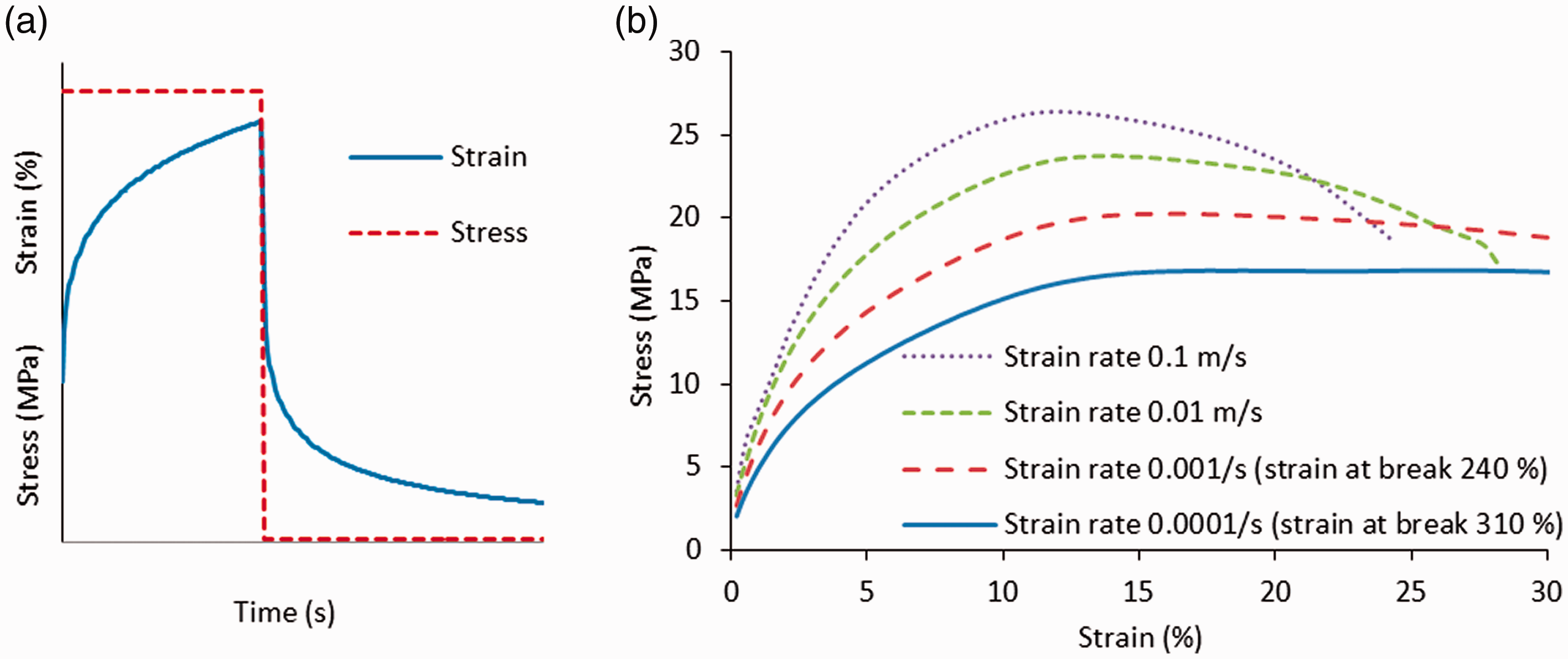
Viscoelasticity also causes strain rate dependent behaviour. The material will exhibit greater stiffness when loaded at a higher strain rate. Properties of polymers therefore have to be assessed at load durations and strain rates comparable to the actual load case. Lampo 2 observes significant differences in stiffness between static laboratory testing of polymer sleepers and dynamic loading in track. Tensile tests performed by the authors on polyethylene at different strain rates (Figure 1(b)) show that Young’s modulus, material strength and strain at break depend on the strain rate.
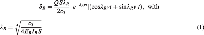
In order to create a representative strain rate when testing polymer sleepers, ISO12856 [20] defines a frequency of 5 Hz to be applied in cyclic load tests. To substantiate this value, the rail deflection curve over time is given, according to the Beam on Elastic Foundation (BOEF) theory
24
Using this equation, Figure 2 shows a BOEF rail deflection curve for a wheel passing at 80 km/h (based on typical European track parameters, table in Figure 2), as well as a sinusoidal loading curve of 5 Hz. The vertical velocity during this loading (derivative of the displacement curve) in Figure 2(b) shows that the maximum vertical velocity of a 5 Hz sinusoidal loading equals that of the specified BOEF loading and is therefore representative for the expected strain rate in the polymer sleeper. This calculation can also be used to verify the applicable test frequency for other train speeds or other track foundation stiffnesses.
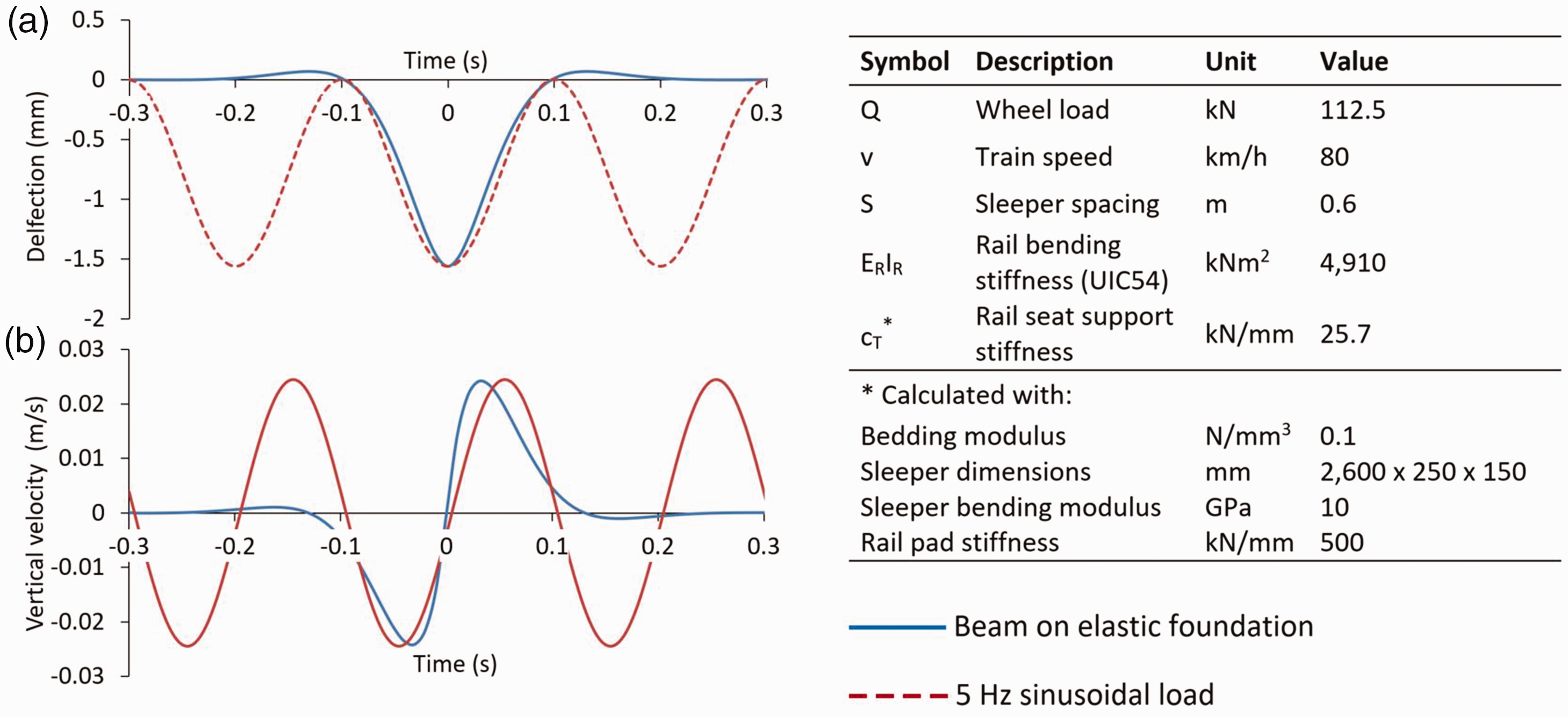
(a) BOEF deflection and (b) Vertical speed curve compared to a 5 Hz sinusoidal load curve in order to approximate the strain rates during polymer sleeper testing. The table provides input as used for the BOEF curve.
When a polymer is loaded, the stress-strain graph follows the non-linear top line of Figure 3. Unloading follows the bottom line, and the energy indicated by the grey area in Figure 3 is released. While a polymer is tested by continuous cyclic loading, this energy has, in contrast to the time frame in track, no time to transmit from the material surface to the surrounding environment and will cause a temperature rise. Ferdous 8 mentions this heating up in cyclic loading of polymer sleepers and recognises that “there is no relationship between operational loads and material fatigue performance”.
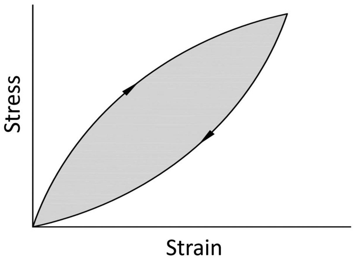
Hysteresis when loading and unloading polymers. 23
During testing of a polymer sleeper with a cyclic load, two effects can be noticed due to the viscoelasticity (Figure 4(a)). Firstly, while the stress amplitude is constant, the strain amplitude will increase over time. The polymer experiences the load as a combination of a constant stress and a fluctuating stress, of which the constant part induces creep and affects deflections, but also polymer strength.22,25 When the sinusoidal load is applied continuously in a test, this will cause higher strains than with actual train loads, where there are pauses between trains, which gives the material time to recover (Figure 4(b)). Introducing pauses in the test regime (intermittent testing) is therefore more in line with the expected loading in track.
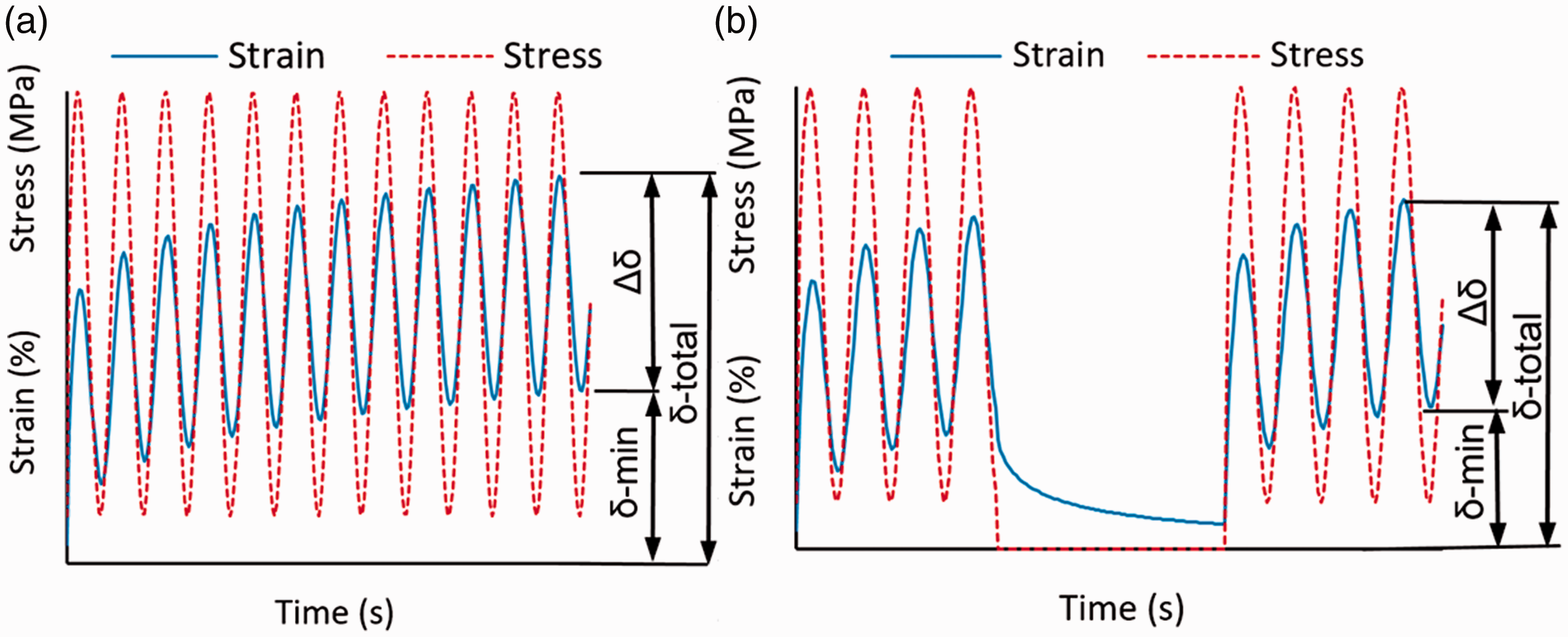
Stress-strain relation of polymers under: (a) Continuous cyclic loading; (b) Intermittent cyclic loading.
Secondly, during continuous testing, heat will build up due to the damping properties of polymers. The polymer temperature will rise and change the material properties, since polymer properties are temperature dependent. 22 Reducing the test frequency would increase the error in testing, as the polymer behaviour depends on the strain rate. Lojda 26 finds that, with cyclic loading of polymer sleepers, a frequency reduction from 5 Hz to 3 Hz or 1 Hz produces a reduction in bending stiffness of 7% or 13%, respectively.
Intermittent cyclic load testing is proposed in this paper as a possible solution. With intermittent testing, most of the test-induced creep and heat accumulation is eliminated. Furthermore, the loading speed is kept at the desired level for track evaluation. Together, this enables a more representative stiffness and strength assessment. A series of tests with polymer sleepers was performed to describe the effect of the proposed intermittent testing and to justify its advantages.
Methods
Three series of sleeper bending tests with varying test arrangements and loading procedures were performed to evaluate the effects of intermittent loading in comparison with continuous loading. Rectangular cross-section sleepers with dimensions of 250 × 150 × 2,600 mm reinforced with steel bars were subjected to the test series. Sleepers of type 201 and 202 represent two different strength variations tested with installed baseplates Rph1 and screw spikes Ss8, which are commonly used for timber sleepers in Europe. Table 1 shows an overview of the tests performed.
Overview of tests performed.
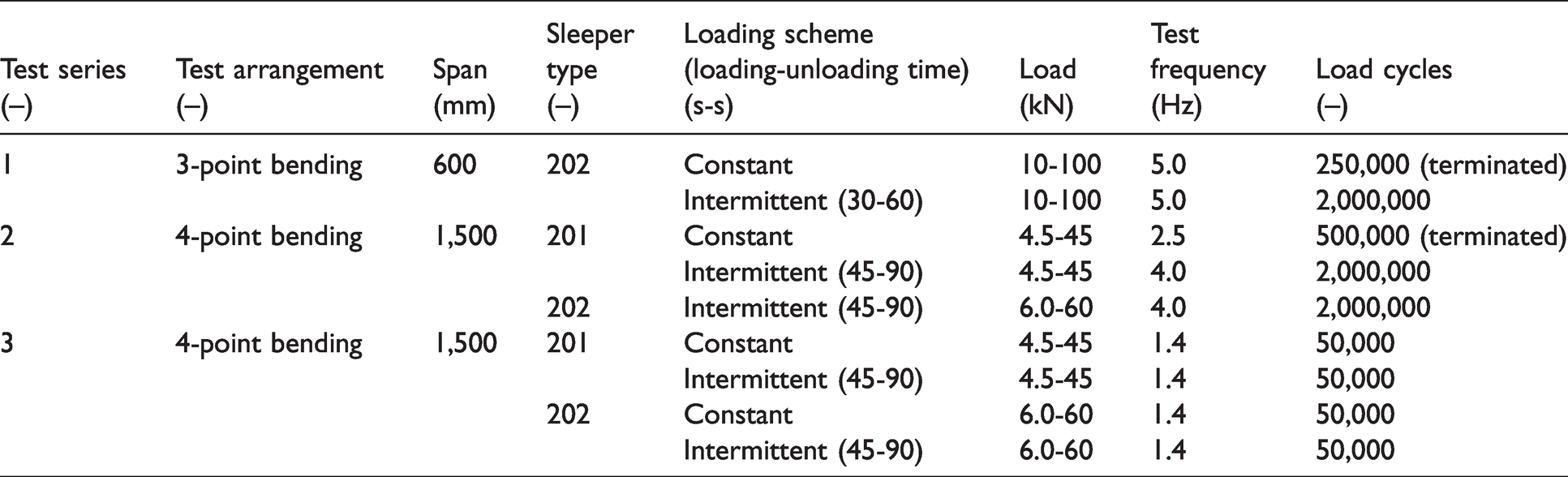
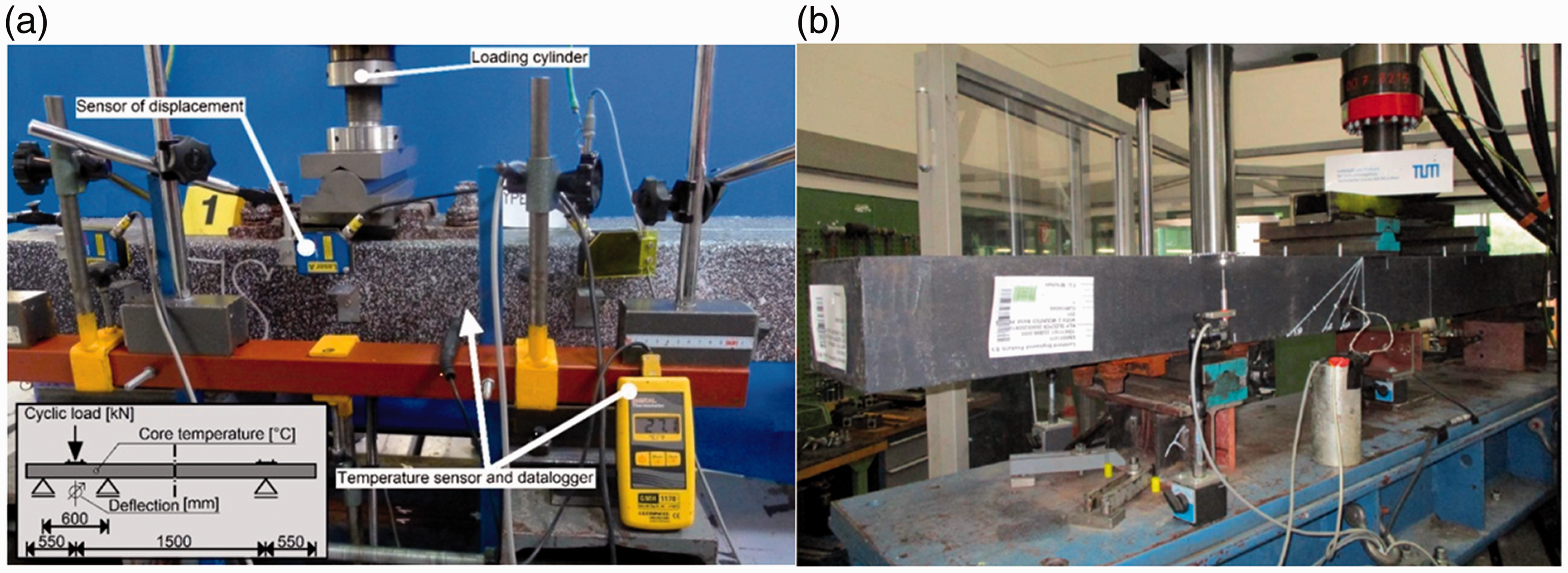
The first test series involved three-point bending tests of type 202 sleepers according to ISO 12856-2 [20] at the railseat of the sleeper with a 600 mm span (Figures 5(a) and 6(a)), performed at Czech Technical University in Prague. The untested sleeper end was freely laid on a third support, which enabled upward movements. Intermittent loading consisted of 30 s of loading and 60 s of pause. 150 load cycles (30 s × 5 Hz) corresponds with the passing of a locomotive and 36 freight wagons, which is a realistic train set (according to the European Railway Agency, a train set length shall not exceed 740 m). Loads were calculated according to ISO 12856-3, 27 creating bending moments as expected in track.
(a) 3-point bending test of sleeper type 202 at the rail seat (600 mm span) performed at CTU in Prague; (b) 4-point bending test of sleeper type 201 at the sleeper centre peformed at TU Munich (1,500 mm span).
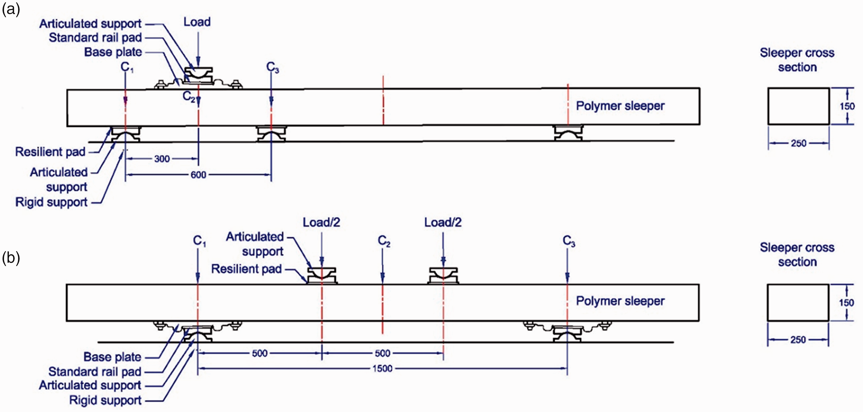
Test arrangements according to ISO 12856-2 of (a) 1st test series and (b) 2nd and 3rd test series.
The second and third test series involved four-point bending tests according to ISO 12856-2 [20] (Figures 5(b) and 6(b)), performed at the Institute of Road, Railway and Airfield Construction of the Technical University of Munich.
Different load levels, test frequencies and loading schemes were applied to two sleeper types (type 201 and 202) to evaluate the influence of intermittent loading and constant loading (Table 1). The intermittent loading scheme consisted of a 45-second loading phase alternating with a 90-second rest period (Frest = 1.0 kN), as defined in ISO12856-2.
For all three test series, the measuring setup consisted of a load cell to measure the acting force. Additionally, inductive displacement sensors as well as laser sensors were applied to record the vertical displacements in the center of the sleeper (Figure 6, C2) and in the axes of the supports (Figure 6, C1 and C3) to evaluate the sleeper deflection. All displacement sensors used had a range of 20 mm with a precision in the range of micrometers. The pure bending deformation δ, without the vertical displacement at the supports, was determined according to equation (2)
In addition, the temperature in the core of the tested sleepers was monitored with temperature sensors.
Results
The first test series involved three-point cyclic load bending tests with 600 mm span at the railseat according to Figure 6(a). Figure 7(a) shows the results of this test, with the orange lines depicting the core temperature of the sleepers (values on right-hand vertical axis). The continuous lines show the continuous cyclic loading, the intermittent lines the intermittent cyclic loading. Intermittent testing continued until 2 milllion cycles had been performed; for a better comparison with the continous test, only part of the graph is shown in Figure 7(a).
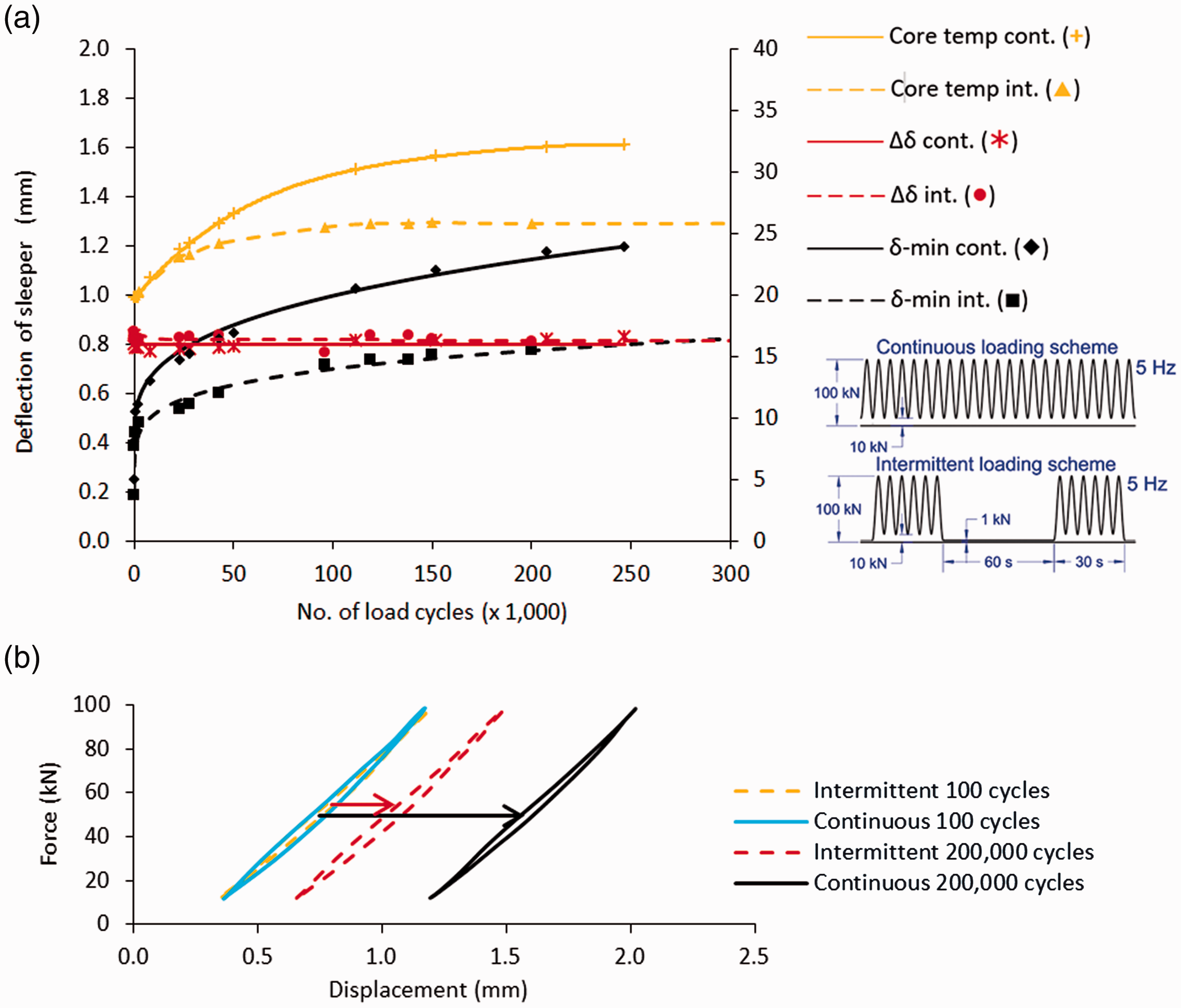
(a) Sleeper deflection as a function of number of load cycles for 1st test series. Sleeper type 202. Test performed at TU Prague according to ISO 12856-2 3-point bending test at 600 mm span, air temperature 19.8–21.4 °C. (b) Force-displacement diagram for 100 and 200,000 cycles respectively.
For the deflections (left-hand vertical axis), two values are given: the black lines give the minimum deflections (δ-min), as explained in Figure 4. The red lines (Δδ) give the difference between the minimum and maximum deflection.The total deflections are not specified in the graph, they are the sum of δ-min and Δδ. This divison was made to provide a clear distinction between the continuous nature of δ-min, versus the short duration of Δδ. The creep behaviour of polymer materials manifests itself in a lower stiffness for longer duration loads, hence the importance of creating this distinction between long and short duration loads.
The continuous cyclic load test had to be stopped after 250,000 cycles due to a continuing temperature rise in the sleeper (Figure 7(a)). The increased temperature reduced the stiffness of the polymer, resulting in greater deformations, which in turn caused even higher temperatures. Ultimately, the deflections exceeded the test machine’s limitations. The intermittent test, performed at the same frequency but with a 60 s pause after every 30 s of loading, showed a temperature rise, but remained stable after 5 × 10⁵ loading cycles.
The two tests give almost identical Δδ values and show a horizontal line, meaning that the type of loading has no noticeable effects on this value. The minimum deflection (δ-min) shows an increase during the test, and shows a greater slope for the continuous than the intermittent test regime. The force-displacement graphs in Figure 7(b) confirm that Δδ remains comparable during the test, but the δ-min value changes more during the test for the continuous test than for the intermittent test.
In a second series of tests, a four-point bending test according to Figure 6(b) was performed on sleeper type 201, with a load frequency of 4 Hz for the intermittent test. For the continuous test, the load frequency was now reduced to 2.5 Hz to prevent a temperature rise. However, temperature and deflection increased during this test. Ultimately the continuous test was aborted after around 500,000 cycles (Figure 8(a)). The ambient temperature varied between 30 +/− 3 °C during the test, which had an effect on the sleeper core temperatures and the Δδ -values. The δ-min values again show an increase during the test, which is more pronounced for the continuous tests than it was before. In the intermittent tests the Δδ value was stable, in the continuous test a slight increase could be detected in the Δδ value until the test was aborted.
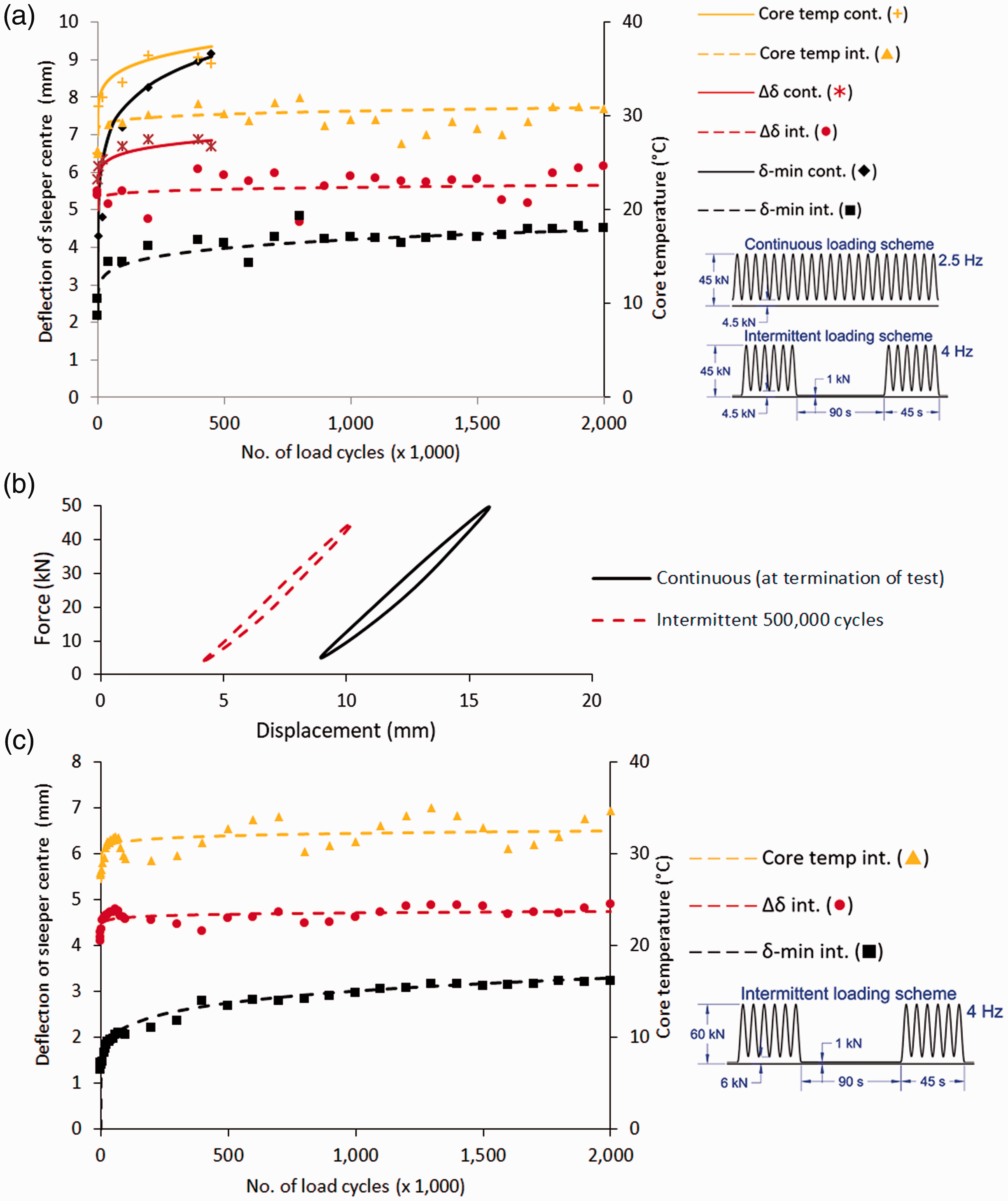
Sleeper deflection as a function of number of load cycles for 2nd test series. The choice of test frequencies is based on keeping the sleeper temperature within specified limits. Tests performed at TU Munich according to ISO 12856-2, 4-point bending at 500-500-500 mm; (a): Sleeper type 201; (b) Force-displacement diagram of sleeper type 201 for 500,000 cycles; (c): Sleeper type 202 (only intermittent test).
Figure 8(b) shows the force-displacement curve for the 201 type sleeper when the continuous test was terminated. The force-displacement loop now shows an increased area.
A second type of sleeper (type 202) was tested, but only for the intermittent regime (Figure 8(c)).
A third test series was performed, now keeping the frequencies of the continous and intermittent test identical, to rule out any difference in material response caused by different strain rates. The frequency was kept low (1.4 Hz) to prevent a temperature rise as much as possible. The test performed was again a four-point bending test according to Figure 6(b).
Figure 9 shows the result for the two sleeper types. Some small variations in core temperatures can be attributed to variations in the ambient temperature. The Δδ values remained constant and are almost identical for the intermittent and continuous test regimes, but the total deflection (δ-min + Δδ) is much lower for the intermittent test regime than the continuous one. Since the frequencies were identical, this effect was caused by creep due to the continuous part of the load. The sleeper did not have enough time to return to its original position, which was the case much more for continuous than for intermittent loading. Under real track conditions, the total deflection would be even lower than during intermittent testing, since unloading times are longer.
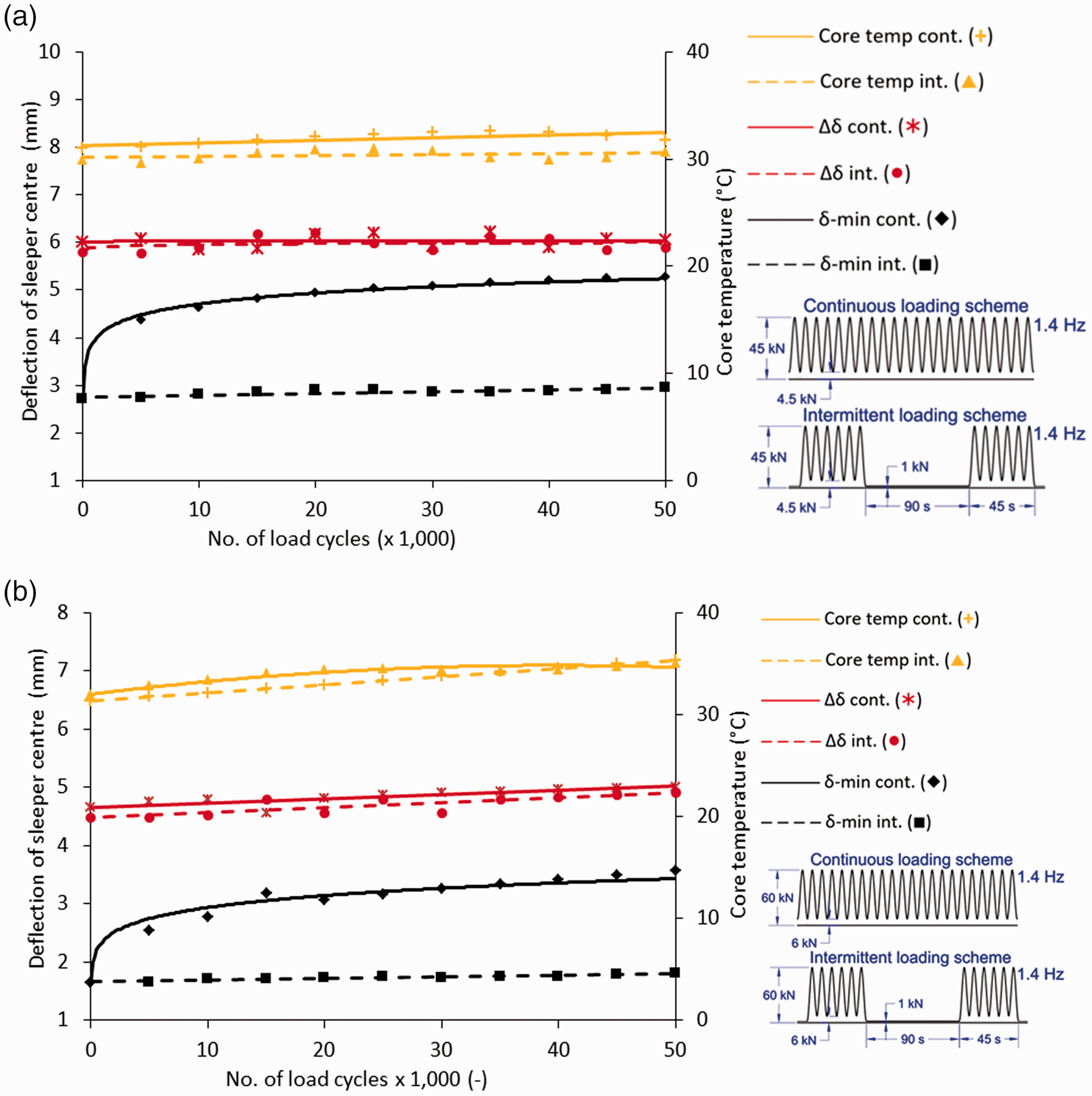
Sleeper deflection as a function of the number of load cycles for the third test series. The test frequencies are identical and at such a low rate that internal heating is minimal. Tests performed at TU Munich according to ISO 12856-2 4-point bending at 500-500-500 mm. (a): Sleeper type 201; (b): Sleeper type 202.
Discussion
The first test series shows that performing tests on polymer sleepers at 5 Hz can cause the sleeper to heat up. The temperature increase will lower the Young’s modulus of the polymer, thus increasing its deflection. The extent of temperature increase depends on the polymer type and the associated hysteresis curve, the strain levels during the test and the amount and magnitude of the load cycles, and is therefore difficult to quantify. Monitoring of the sleeper core temperature is necessary in any case. The temperature rise is created by the hysteresis minus the remittance of energy to the sleeper surroundings. Intermittent testing gives the sleeper more time to balance heat with its surrounding environment, thus reducing the temperature of the sleeper. Intermittent testing therefore tends more to the loading situation in track, where there is time between trains.
The second test series shows that lowering the test frequency in a continuous test does not neccesarily solve the heating issue. The continuous test showed larger deflections due to the lower polymer stiffness at a lower frequency. As a result of the increased hysteretic heating, combined with the absence of rest periods, the deflection increased further. The value Δδ is an important one to evaluate correctly, as this is the deflection experienced by each wheel passing over the sleeper. When the test frequency is reduced, the strain rate and associated deflections no longer correlate to those representative of track behaviour.
The third test series shows that even when frequencies are identical and the temperature rise does not play any significant role, δ-min grows due to creep during the test, since δ-min can be regarded as a continuous load on the sleeper. Intermittent testing transforms this continuous load into a series of loads of shorter duration, with the aim of the polymer returning asymptotically to its initial state.
The total deflection for both sleeper types was 22% lower for intermittent testing than for continuous testing in the third test series. The magnitude of difference between a continuous and an intermittent testing regime for other sleeper types may depend on the type of polymer used, the sleeper composition, the applied loads and the test frequency.
Furthermore, in the third test series, Δδ seems to be identical for intermittent and continuous testing and does not change over time (a small increase of Δδ over time is noticed, but this could be attributed to a temperature rise). This seems logical, since Δδ is caused by a short duration load. When looking solely at the Δδ value, one could argue that the continuous test and the intermittent test give the same stiffness values and are thus interchangeable. This is not entirely true, however, since the stress-strain curve of a polymer is non-linear (Figure 1(b)). The addition of the higher δ-min deflection for continuous testing will lead to a higher total deflection, and thus to a lower stiffness. In the test, this could not be explicitly observed in the Δδ values.
Intermittent testing transforms the continuous δ-min load into a series of loads of shorter duration, with the aim of giving the polymer time to recover asymptotically to its initial state. The pauses in these test series are twice as long as the load duration (60/90 second pause versus 30/45 seconds loading, respectively). This pause is shorter than it would normally be in track. The graphs in test series 3 show that the deflections are still increasing slightly over time. Therefore, intermittent testing with the chosen load and rest duration is not the perfect solution and still represents a compromise between the time needed for testing and the validity of the result. A load and rest duration equal to that in track will give the most valid result, but testing would take years.
Figure 1(b) shows that faster loading of polymers leads to higher strength values. The load situation in track is a short duration load. The cyclic load laboratory test is a combination of a short duration load (Δδ) with a long duration load (δ-min). This combination of loads results in a lower material strength than in a real track. With intermittent testing, the load duration for δ-min is reduced significantly, thus giving a more representative test outcome, although strength values were not examined extensively during this test.
The intermittent method for cyclic load testing has been adopted by the ISO committee on polymeric composite sleepers and will form part of the ISO 12856-2 testing methodology as an optional testing method. For loading and pausing durations, 45 seconds and 90 seconds were chosen respectively, as a worst-case situation in track. For polymeric materials that show little heating and creep during testing, the method is not necessary, but when heating makes it necessary to slow down testing or when creep effects become significant, intermittent testing is the preferred method.
Conclusion
During polymer composite sleeper testing, cyclic load tests are a routine part of the tests used to assess sleepers in a laboratory before employing them in track. In such a test, the loads are applied without rest periods to condense the test and save time. However, most polymers possess viscoelastic properties, such as creep, a loading rate-dependent stiffness and heating due to non-linearity of the stress-strain curve. When a continuous cyclic load test is used, two things happen: The material heats up due to hysteretic heating The material experiences creep due to the constant part of the load
A sleeper temperature increase, increased deflections and reduced strengths are witnessed in continuous cyclic load tests, which are not representative of track behaviour.
An intermittent test method is proposed and tested, in which there are pauses, for example a pause of 90 seconds after every 45 seconds of cyclic loading. The tests show that an intermittent test regime is effective and reduces unwanted vicoelastic side effects, such as heating of the sleeper and creep. The choice of the best loading-unloading regime will always be a trade-off between the time needed to perform the test and the validity of the results in track. The longer the pauses, the more the results will resemble the situation in track, but also the longer the test will take. For polymer materials that show minor vicoelastic effects, the intermittent test regime does not add much value. However, for the polyolefin material used for most polymer sleepers, heating or creep effects can become significant, and intermittent testing provides a more representative result than reducing the load frequency would.
Footnotes
Declaration of Conflicting Interests
The author(s) declared no potential conflicts of interest with respect to the research, authorship, and/or publication of this article.
Funding
The author(s) received no financial support for the research, authorship, and/or publication of this article.