
Abstract
Railway sleepers experience bending moment stresses when subjected to railway traffic. These stresses are influenced by various parameters, such as loading, support conditions or the sleeper material. Approaches for the calculation of relevant bending moments currently exist only for prestressed concrete sleepers. For sleepers made of other materials, there are neither in-depth studies or literature on their bending stress nor calculation methods for determining the bending moments. Therefore, several 1000 calculations were carried out with the aim of depicting the stresses acting on sleepers in ballast. For these calculations, the theory of the beam on elastic foundation was used, with the help of which combinations of different support and loading conditions as well as of other parameters were investigated. By analysing the results focussing on the bending moments resp. the lever arms causative for these moments, it was possible to establish a correlation between the results obtained. Based on this correlation, a procedure for the determination of the lever arms independently from the load introduction length was developed. In combination with the scaling of the results over the elastic length of the sleepers, considering the track modulus as well as the sleeper geometry and material properties, this resulted in a generally valid, material-independent method for determining the moment stress of sleepers of constant cross-section, independent of the load introduction length.
Keywords
Content detailed hereafter is mostly part of the dissertation ‘Development of a material-independent verification procedure of railway sleepers’, 1 which was published in 2020 at the Technical University of Munich. So far, the thesis and all information contained have been published exclusively in German.
Introduction
For the calculation of theoretical bending stresses on concrete sleepers, two concepts exist in Europe – that of UIC Code 713 2 and that of EN 13230-6. 3 Apart from these methods, there are no actual standardised procedures in Europe for determining such stresses for sleepers made of other materials.
The ballasted superstructure as an overall system exhibits a high degree of complexity in its interrelationships. In order to obtain information on the behaviour and stresses of sleepers, a theoretical analysis is therefore only possible by assuming simplifications. The approach of a beam on elastic foundation with limited length represents here a suitable method.
This approach is for example also mentioned as an optional calculation method in EN 13230-6. In this case, the moment stresses of individual sleepers is to be determined by means of a finite element calculation.
Common, application-oriented finite element software is suitable for determining the desired parameters. Calculations by different users can produce completely different results, if the simulation models do not coincide right down to the last detail. Possible reasons for this are for example the input or software implementation of material parameters, the meshing of the model or the definition of contact surfaces.
In order to ensure better comprehensibility of the assumptions and processes, the investigations were carried out by means of extended hand calculations. These have been conducted on the basis of the theory of the beam on elastic foundation using the subgrade reaction modulus method.
Delimitation of the investigation scope
With regard to the application of the theory of the beam on elastic foundation with limited length for the calculation of internal forces in railway sleepers, various aspects or boundary conditions have to be considered. Before setting up different calculation models, it is first necessary to define the limits of the investigation scope. The sleeper geometry, the material properties of the sleeper, the loading and the support situation are the relevant parameters.
The sleepers typically used in Germany are 2.4 and 2.6 m long. In addition, bearers with a minimum length of 2.2 m are used. 4 Consequently, the three aforementioned sleeper lengths of 2.2, 2.4 and 2.6 m were defined as parameters for the model generation. Since the focus of these investigations was on main-track sleepers or sleepers with rail seats arranged symmetrically to the sleeper centreline, no consideration was given to special shapes or asymmetrically loaded sleepers.
In view of the focus on the German railway network, the investigations were limited to the sleeper cross-sections usually used here. Accordingly, the cross-sectional dimensions of 260 mm × 160 mm (w × h) and 260 mm × 150 mm defined in the Deutsche Bahn Standard for wooden sleepers 5 were selected. The dimensions of 260 mm × 160 mm also represent the standard cross-section for wooden bearers. 5 Furthermore, a cross-section of 300 mm × 200 mm was defined, based on the cross-section geometry of a prestressed concrete sleeper B93 or B93.1. For simplification, the trapezoidal cross-section has not been taken into account.
For the numerical representation of the systems, a basic definition of section lengths was required. In addition to the definition of the sleeper lengths to be considered, the distance between the rail foot centrelines or the load application points was the second decisive dimension. Due to the focus of the investigations on the German railway network, the considerations were made exclusively for the standard gauge with a gauge of 1435 mm, for which the rail foot centre distance for the modelling was simplified to 1500 mm.
The general theoretical considerations on sleeper stresses are based on the assumption of three nominal states. These are the states of the freshly tamped superstructure (case (a), Figure 1), with a support-free area in sleeper centre, the partially consolidated superstructure (case (b), Figure 1), with 50% less pressure in sleeper centre compared to the area of the rail seats, as well as the consolidated superstructure (case (c), Figure 1), with constant supporting over the entire length of the sleeper. The bearing situations to be investigated were limited to these cases.

Nominal states of the sleeper supporting in ballast.
According to the superstructure calculation of Deutsche Bundesbahn, 6 the support-free area in the centre of the sleeper is assumed to be 500 mm long. This is in contrast to the calculation assumption of EN 13230-6, 3 which determines the length of the unsupported area according to geometrical and symmetry-related parameters. Here, the distance from the rail foot centreline to the end of the sleeper must also be transferred in the direction of the sleeper centreline. In this way, the supported and consequently also the unsupported sleeper area is defined. For a sleeper with a length of 2600 mm, using the rail foot centre distance of 1500 mm results in a support-free centre section with a length of 400 mm. However, a reduction in sleeper length theoretically results in an increase in the support-free area in the sleeper centre. From a purely geometrical point of view, the increase in the support-free centre section would lead to a shortening of the lever arms in the support area and would thus result in a reduction in the bending moments at rail seat. With regard to a theoretical consideration of the maximum stresses occurring in connection with usual loads and support conditions, such a reduction of the moments would be seen as an underestimation of the stresses and would therefore be on the unsafe side. Therefore, only the approach of a support-free length of 400 mm, corresponding to the method to be applied according to EN 13230-6 for a 2600 mm long sleeper, seemed reasonable. For this reason, it was decided to use unsupported lengths of 400 and 500 mm for the investigations. For the illustration of the partially consolidated state, the identical section lengths were defined. Special abbreviations have been introduced in order to clearly distinguish between the support cases:
Support-free centre section of 400 mm length → AM400
Support-free centre section of 500 mm length → AM500
Partially bedded centre section of 400 mm length → TB400
Partially bedded centre section of 500 mm length → TB500
Full-surface support → VL
In light of a material-independent investigation, the parameter of the material properties could not be narrowed down to a single value. Due to the fact that the measurement parameters for the calculations of the beam on elastic foundation are to be applied in the form of the modulus of elasticity, a corresponding consideration range was defined. Unpublished test series at the Institute of Road, Railway and Airfield Construction of the Technical University of Munich, in which elastic moduli of various plastic and wooden sleepers were determined on the basis of three-point bending tests, formed the foundation for defining the lower limit of the aforementioned range. In contrast, the modulus of elasticity of concrete sleepers constituted the basis for defining the upper limit of the investigation range. According to the European concrete sleeper standardisation 7 , the concretes to be used in sleeper production must have a minimum compressive strength class of C45/55, with an average modulus of elasticity of 36,000 N/mm2 . 8 According to the requirements of the Deutsche Bahn Standard for concrete sleepers, 9 a compressive strength class of at least C50/60, with an average modulus of elasticity of 37,000 N/mm2, 8 is even required. By assuming all values in compression as well as in tension direction, the influence of reinforcement on the modulus of elasticity could be directly taken into account. To cover the widest possible spectrum of elastic moduli, the range of consideration was extended beyond the previously mentioned values and defined with a lower limit value of 1000 N/mm2 and an upper limit value of 60,000 N/mm2. Since the current approaches for determining sleeper stresses are valid only for concrete sleepers, no basis existed for subdividing the moduli of elasticity to be investigated. As a result, knowledge of the properties of known sleeper materials was used to define grid points of the elastic modulus matrix to be considered. The gradations between these points were obtained according to the most reasonable compaction of the material parameters to be investigated, without unnecessarily extending the number of cases to be investigated. Consequently, the calculations have been based on elastic moduli of 1000, 2500, 5000, 7500, 10000, 12500, 15000, 20000, 30000, 40000, 50000 and 60000 N/mm2.
The subgrade reaction modulus is usually used to represent the subgrade conditions and the stiffness of the ballast superstructure. However, it is not possible to make a generally valid assumption because of the wide variety of boundary conditions. As can be seen from the superstructure calculation of Deutsche Bundesbahn, 6 different moduli of subgrade reaction can be used depending on the quality of the subgrade. The quality levels range from a very poor (C = 0.02 N/mm3) to a very good (C = 0.15 N/mm3) subgrade. In addition to these levels, a subgrade reaction modulus of at least 0.30 N/mm3 is defined in the presence of a concrete base. According to Eisenmann, 10 this range of consideration can be limited to a maximum value of the subgrade reaction modulus of 0.40 N/mm3 in the case of compacted subsoil and compacted base course, rock subsoil or a concrete base. Within the framework of the superstructure calculations 6 as well as the publication by Eisenmann, 10 a gradation of the modulus of subgrade reaction in steps of 0.05 N/mm3 was partly used. This gradation was also used here for the determination of the individual values. Only the lowest modulus of subgrade reaction (C = 0.02 N/mm3) deviated from this grid. Accordingly, the subgrade reaction moduli of 0.02, 0.05, 0.10, 0.15, 0.20, 0.25, 0.30, 0.35 and 0.40 N/mm3 were used as input values for the calculations.
In combination with the selected moduli of subgrade reaction and elastic moduli, this resulted in 108 variants that had to be considered in the calculation of each sleeper length, cross-section geometry and support condition. By exploiting symmetry, the consideration could be reduced to half the system. Accordingly, subsequent investigations were limited to the analysis of the left half of the sleeper.
Finally, a choice regarding the loading situation to be applied was necessary. A distinction must be made between two basic variants. In the case of a direct fastening or a base plate fastening system, the load is applied over a defined area. Line loads that are close to reality can represent this. Alternatively, it is also possible to use the simplified approach of loading by means of point loads, which can be implemented with less effort. This approach represents a local concentration of the load introduction and allows higher values of the internal forces to be expected at the points of loading, compared with the approach of line loads. The corresponding results consequently represent a higher local sleeper stress and are therefore on the safe side. A selection of the loading situation was mandatory before the model was created, since this results in differences in the approach of the modelling.
For implementing the calculation of a sleeper in ballast, based on the theory of the beam on elastic foundation, and solving these systems, a numerical solution approach was followed. Strictly speaking, this approach was not a complete numerical solution of the systems, since external stresses were left as variables in the systems of equations. Accordingly, the initial definition of a support point load, represented by point loads F or line loads q ( x ), could be omitted. For the other parameters, an assignment of numerical values was carried out. As a result of this procedure, the solution of the equation systems became feasible with usual computing power and acceptable computing time. The MATLAB R2016a software was used to implement and perform the calculations.
In order to distinguish and clearly assign the various investigation cases, special abbreviated designations are used in the following. These result from the levels of the examination structure and consist of three capital letters. The first letter describes the constant sleeper geometry G. The second letter differentiates between the load situations point load E and line load S. The third letter of the abbreviated designation distinguishes between the support situations support-free centre section A, partially bedded centre section T and full-surface support V.
Theoretical backgrounds
The theoretical principles presented and applied below, which were used to develop the method described in the following, are based on the work of Hayashi 11 and other publications in engineering mechanics.12,13
First, it is necessary to define the positive direction of action of the internal forces and the external loads. The corresponding definitions can be found in Figure 2 (p. 5) and in the following list.
• Deformation or subsidence y→ downwards
• Angle of inclination φ→ clockwise
• Transverse force Q, left of element → upwards
• Transverse force Q, to the right of the element → downwards
• Moment M, left of element → clockwise
• Moment M, right of element → anticlockwise
• external force F or q→ downwards
• external moment Mext→ anticlockwise

To represent a system using the approach of the beam on elastic foundation, knowledge of basic boundary conditions and processes is required in advance. To enable a calculation, the entire system must be subdivided at defined points. The beginning or the end of such a subsection are the so-called discontinuity points. At these points, there is a variation in boundary conditions, such as a change in the support conditions, the loading situation or the sleeper cross-section.
The basis of the theory of the beam on elastic foundation is Winkler’s hypothesis. According to this hypothesis, the foundation reacts with a counterpressure, which is proportional to the subsidence of the beam.11,13

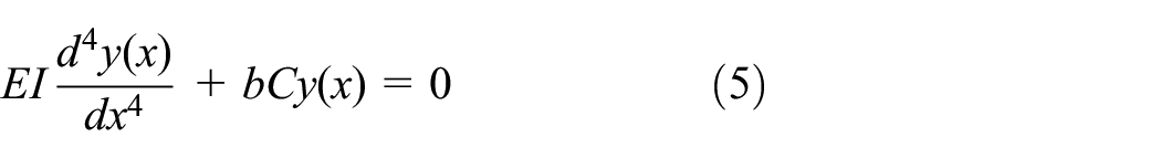
Applying this hypothesis in conjunction with the differential equation of the fourth-order bending line according to the beam theory, the differential equation of the bending line of the beam on elastic foundation is obtained.11–13

By using the simplification of the elastic length L and restricting the validity to the case of a constant bending stiffness E I as well as a constant bedding factor b C, the general solution of the differential equation can be formulated.11,13

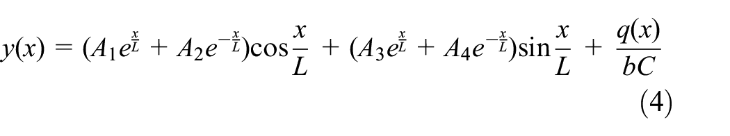
Based on this general solution, it is possible to set up the equations for the different sections of a sleeper to be examined.
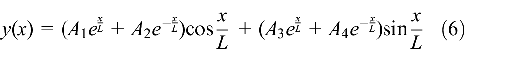
In the case of point loads, the parameter of the line load q ( x ) in equation (2) must be set to zero. Thus q ( x ) is omitted from the differential equation of the bending line of the beam on elastic foundation as well as from the general solution of the differential equation.11,12
The parameters A1, A2, A3 and A4 from the general solution of the differential equation of the bending line of the beam on elastic foundation represent the four integration constants. These must be defined using boundary and transition conditions. In order to determine all integration constants, it is necessary to set up at least one, usually several further equations of the elastic quantities. 13 According to the differential relations of the beam theory, the equations of the elastic quantities result as derivatives of the bending line.14,15

These equations are valid since small deflections and small angles of inclination are generally assumed. The linear differential equation used in these investigations is only applicable for angles of inclination ≪ 1 rad. The upper limit value is an angle of 10°, corresponding to 0.1745 rad. For the case of larger angles of inclination, a calculation by means of a non-linear differential equation is necessary.14,16
To enable independent equations of the elastic line to be drawn up for different sections of the system, an additional group of conditions is applied at the discontinuity points. The indices l and r describe the edge to the left and right of the transition point. In the event that no local load or moment is applied at the corresponding point, F and Mext are to be set to zero. 11

Within the scope of the investigations, the coordinate zero point of the control variable x was defined at the left edge of the respective overall system. The control variable was continued across the boundaries of the subsections. Accordingly, no further zero points or subdivisions of the control variable were defined at the intersections of the system.
Investigations – point loads
For setting up the investigation systems, the sleepers had to be subdivided into appropriate sections according to the respective support situation. Due to the constant cross-section, an additional, geometry-related subdivision was not necessary.
The preparation of the model for sleepers with a support-free centre section (GEA) required the definition of three subsections. The first section AB represented the area from the end of the sleeper to the load introduction, the second section BC the area from the load introduction to the beginning of the support-free centre section and the last section CS the support-free area, from its beginning to the sleeper centre or symmetry axis. A graphical representation of the described area subdivision can be seen in Figure 3.

Half-sleeper with support-free centre section and loading by a point load, investigation case GEA.
Conceptually, the use of this system design was possible for both dimensions of the support-free centre section. However, varying the length of the support-free area also resulted in a change in the length of the adjacent area. For the different sleeper lengths, the section lengths shown in Table 1 resulted.
Overview of the sleeper and section lengths used in the investigation case GEA.

No further modelling adjustments were necessary to implement the different cross-section geometries. Due to the method of calculation, the different sleeper cross-sections could be taken into account by changing the corresponding input values numerically. Only the dimensions of the cross-section had to be adjusted.
The direct depiction of the support-free centre section was not possible due to the calculation method of the theory of the beam on elastic foundation. Since the use of a subgrade reaction modulus of 0 N/mm3 would have led to the indefiniteness of part of the expressions, the bedding of the support-free area had to be represented by means of a value of the subgrade reaction modulus that was as small as possible but still meaningful. It proved practicable to use a ratio value of 1/100, based on which the modulus of subgrade reaction of the supported area was reduced and the modulus of subgrade reaction for the support-free area was defined. For example, for a regular modulus of subgrade reaction of 0.40 N/mm3, the modulus of subgrade reaction for the centre area resulted to 0.004 N/mm3. Using this system for defining the bedding in the theoretically support-free area, problems in the calculation procedure could be avoided. A further reduction of the modulus of subgrade reaction in the centre area by applying a reduction factor of 1/1000 resulted in a deviation of the results of maximum 0.2% in the cases analysed. This difference was considered to be negligible, so that the reduction value of 1/100 was used as the standard parameter for all further calculations of the ‘support-free centre section’ case.
To represent the unbedded sleeper area, the implementation of an additional elastic length was necessary to enable the approach of the subgrade reaction modulus for this delimited area (Figure 4). Accordingly, all equations of the elastic quantities could be set up for the three subsections of the sleeper.

Calculation structure of the investigation case GEA.
The solution of these systems of equations required the definition of a total of twelve boundary and transition conditions. In this context, it should be mentioned that the definition of the conditions for all calculations was carried out according to a consistent scheme, which can be seen in Figure 5. Two specific boundary conditions were applied at the edges of the systems, namely at the end of the sleeper (x = 0) and in the sleeper centre (x = l0 / 2). The remaining conditions were obtained by equating the elastic quantities at the transition points. In the case of loading with point loads, the force at the point of load application was additionally to be taken into account according to the definition given in the ‘theoretical backgrounds’ section.

Scheme of the definition of the boundary and transition conditions.
In order to have the results of the calculation available for further use, it was necessary to define a step size of the control variable x and thus of the evaluation points. The most important aspect here was to obtain results at the point of load introduction (B) and in the sleeper centre (S). Accordingly, the step size of the control variable x along the longitudinal axis of the sleeper was chosen to be 10 mm.
For the investigation of the case of partial bedding in the sleeper centre (GET), the model was created with the same number of sections and identical sleeper and section lengths (Table 1) as for the modelling of the case of bedding with a support-free centre section (GEA). The only difference between these two models was the representation of the ballast in the section CS. As a transitional state between a bedding with a support-free centre section and a full-surface bedding, the modulus of subgrade reaction in the sleeper centre section was assumed to be 50% of the modulus of subgrade reaction of the regularly bedded sleeper sections. Accordingly, a reduction factor of 1/2 was used to reduce the initial modulus of subgrade reaction. Figure 6 shows the sleeper sections used and the area of the reduced modulus of subgrade reaction. Due to the other similarities with the sleeper model with support-free centre section, the same twelve boundary and transition conditions as well as the identical step size of the control variable x were used for this case.

Half-sleeper with partially bedded centre section and loading by a point load, investigation case GET.
As the last model variant of this investigation section, the system of the full-surface supported sleeper (GEV) has been implemented. Here, discontinuities only occurred at the points of load introduction. Thus, only a segmentation of the half-sleeper into two sections was necessary. A subdivision into the section AB, from the end of the sleeper to the point of load application, and the section BS, from the point of load application to the symmetry axis of the sleeper, has been carried out (Figure 7).

Half-sleeper with full-surface support and loading by a point load, investigation case GEV.
For numerical analysis, the section lengths, depending on the different sleeper lengths, were obtained according to Table 2.
Overview of the sleeper and section lengths used in the investigation case GEV.
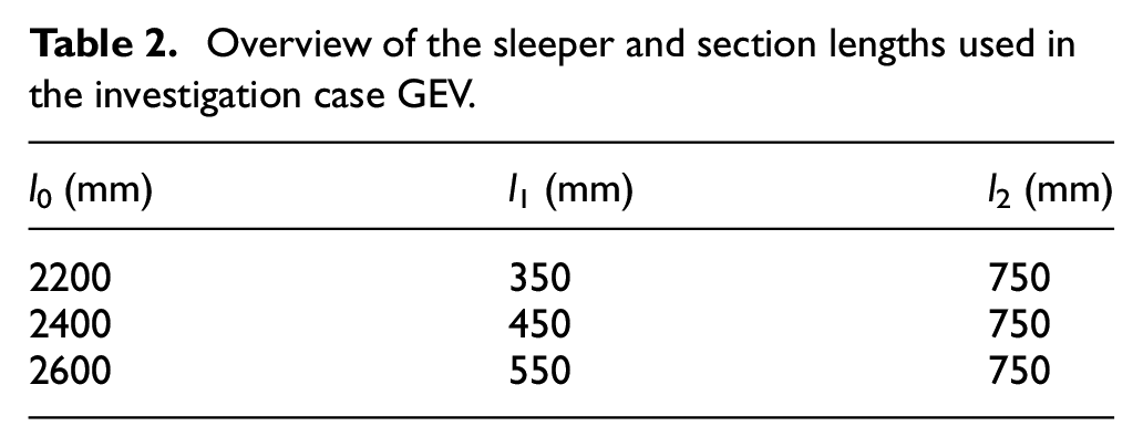
Figure 8 shows the basic structure of the calculation for this case. Since no additional evaluation points had to be taken into account in connection with the full-surface sleeper support, an increment of the control variable x of 10 mm was also used in this case.

Calculation structure of the investigation case GEV.
As expected, the comparison of the calculation results of the three different support conditions showed differences with regard to the deformations of the sleepers and the resulting moment stresses. To illustrate the heterogeneity of the results, they are summarised in Figure 9, reduced to the cases of maximum stress. As an example, a sleeper with a cross-sectional area of 260 mm × 160 mm, a length of 2600 mm and a modulus of elasticity of 10000 N/mm2 was used, applying a subgrade reaction modulus of 0.10 N/mm3. The modulus of elasticity was chosen to represent the material properties of a sleeper made of beech wood. Since the load was not taken into account numerically in the calculation, the values shown represent scaling factors only, which are to be multiplied by the respective support point load.
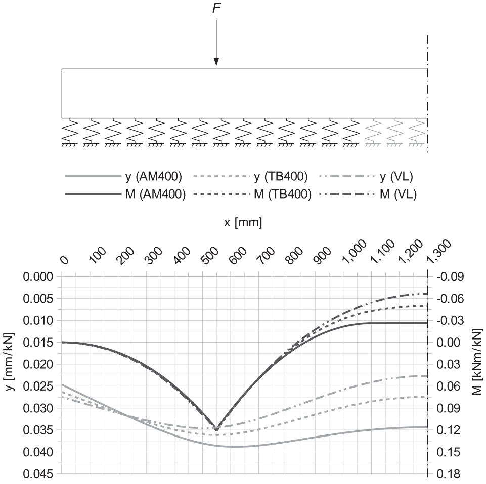
Deformation and moment curves of the investigation cases GEA, GET and GEV (260 mm × 160 mm, l0 = 2600 mm, E = 10000 N/mm2, C = 0.10 N/mm3).
Based on the moment curves, it is clear for the example case shown here that the centre moment has the smallest value for the case with a support-free centre section and the largest value for the case with full-surface support. In addition, the effects of considering a beam on elastic foundation are clearly recognisable in view of the almost identical bending moments at rail seat for all three support conditions.
In the analysis of further data sets, no maximum values of the moment stress in connection with the support condition with partially bedded centre section, neither in the area of the rail seat nor in the sleeper centre, could be determined. Since in practice work on the superstructure is usually only necessary after full surface support has been achieved, the calculation of the stresses resulting from the support condition with partial bedding in the sleeper centre does not offer any added value and was therefore not taken into account for the further considerations. Should it nevertheless be necessary to carry out superstructure work before the fully consolidated state is reached, the stresses determined on the basis of the other two cases can be regarded as being on the safe side.
As can be seen in Figure 9, the load application by means of point loads caused a local peak of the moment stress under the rail seat in all cases investigated. The reason for this occurrence is the method of calculation, in which no direct incorporation of the component or sleeper height takes place. Accordingly, a load propagation in the material and thus a distribution of the moment stress remains unconsidered. Since such an effect exists de facto, an extended analysis taking distributed loads into account was necessary. This could be realised based on the approach of line loads.
Investigations – line loads
The change of the load concept, from load application by point loads to load application by line loads, was possible with minor modifications. The model of the sleeper of constant cross-section with loading by point loads was used as a basis. Since the general solution of the differential equation of the bending line of the beam on elastic foundation (equation (4)) basically contains a term for the consideration of line loads, which could be omitted for the case of investigation of loading with point loads, only an integration of this functional equation and the associated derivatives had to be carried out for the loaded sleeper section. For the sleeper areas without external load, the previously used functional equations could still be applied.
Due to the adjustment of the loading method, the point load and the associated discontinuity point had to be removed from the system. To implement the line load, the loaded area needed to get delimited. Therefore, two discontinuity points had to be integrated again. For the sleeper with support-free centre section and loading by line loads, this resulted in five discontinuity points or four investigation sections. As can be seen in Figure 10, these ranged from the end of the sleeper to the beginning of the line load (AB), over the entire line load area (BC), from the end of the line load to the beginning of the support-free area (CD) and from the beginning of the support-free area to the sleeper centre line (DS).

Half-sleeper with support-free centre section and loading by a line load, investigation case GSA.
As a result of the change in load input, the point load parameter had to be removed from the boundary and transition conditions. However, it was necessary to extend the conditions with regard to the additionally inserted section.
By specifying the corresponding numerical values, the extension of the support-free area and the load were defined. Four different load introduction lengths have been selected, which were applied at the point of loading over the entire width of the sleeper. Load introduction lengths of 125 mm (q125), corresponding to the foot width of rail types 49E5 and 54E4, 17 150 mm (q150), corresponding to the foot width of rail type 60E2, 17 as well as 300 mm (q300) and 400 mm (q400) were used. The latter two values have been chosen to represent a load propagation over the sleeper height. Table 3 shows the sleeper and section lengths considered in the investigation case of a constant cross-section with a support-free centre section and loading by line loads (GSA).
Overview of the sleeper and section lengths used in the investigation case GSA.

In the case of the full-surface support, the definition of four discontinuity points and correspondingly three investigation sections was necessary. Due to the omission of the support-free area and the associated change in the support conditions, the analysis could be carried out without taking the discontinuity point D into account. Consequently, the third section had to be extended from the end of the line load to the axis of symmetry (CS), as shown in Figure 11.

Half-sleeper with full-surface support and loading by a line load, investigation case GSV.
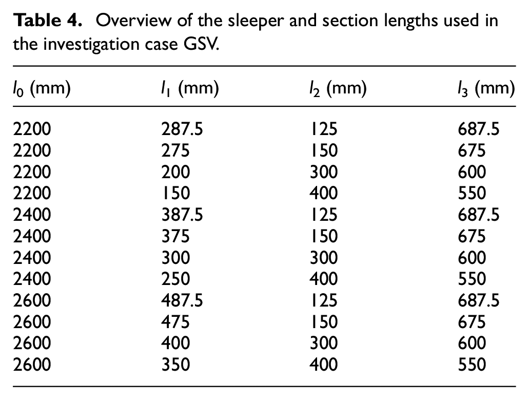
The sleeper and section lengths used for this investigation case are listed in Table 4.
Overview of the sleeper and section lengths used in the investigation case GSV.
In view of the changed loading concept, the step size of the control variable x was modified and uniformly set to 2.5 mm for the cases with loading by line loads. Figure 12 shows the results of the two investigation scenarios, using the example parameters already known from the sleeper with loading by point loads. The results of the calculations with line loads of an extent of 150 mm are shown here as an example.

Deformation and moment curves of the investigation cases GSA and GSV (260 mm × 160 mm, l0 = 2600 mm, lq = 150 mm, E = 10000 N/mm2, C = 0.10 N/mm3).
Also in connection with the loading by line loads, only scaling factors are to be taken from the corresponding figures, which are to be multiplied by the respective support point load.
For comparison or verification of the calculations made with loading by line loads, investigations using FEM were carried out. A limited number of eight representative combinations, used for the extended hand calculations, was considered in order to check the results on a spot point basis. When assuming a theoretical wheel load of 100 kN, this comparison showed maximum deviations of the subsidence y of 0.06 mm or of the bending moment M of 0.09 kNm. Due to these small variances, the hand calculations were considered confirmed.
A comparison of the results of the sleeper loading by point loads and the loading by line loads illustrates the differences between these two approaches. Figure 13 shows this superposition of results, for which the case of a sleeper with full-surface support and loading by point loads (F) as well as by line loads with a length of 150 mm (q150) and 400 mm (q400) was used exemplarily. The illustration clearly shows the distributed load, with load application by line loads, and the resulting moment filleting in the area of the rail seat. The realistic approach of line loads leads in this example case to a reduction of the rail seat moment of 15% (q150) or 39% (q400) compared to the loading by point loads. As expected, the correspondence of the centre moments of both types of loading is additionally evident. No fundamental differences can be observed in connection with the subsidence values.
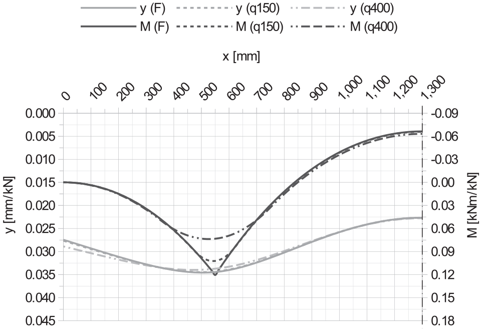
Deformation and moment curves of the investigation cases GEV and GSV (260 mm × 160 mm, l0 = 2600 mm, E = 10000 N/mm2, C = 0.10 N/mm3).
Derivation of the calculation method
Numerical investigations only provide results for a specific case. Therefore, a broad basis of input parameters was defined and a large number of calculations were carried out based on these values. This resulted in the creation of an extensive collection of data for further use and the derivation of a calculation method. The data compilation was based on 14580 calculations for sleepers of constant cross-section.
Some of the investigations showed a lifting of the sleeper at the end or in the centre. The ballast bed is not capable of counteracting the lifting. As this is not automatically taken into account by the calculation method, the models would have had to be adjusted individually for each case and the subgrade reaction modulus would have had to be set to zero for the areas of lifting. However, the models were not revised. Instead, the affected cases were not taken into account for the evaluation.
Basically, the bending moments at rail seat and in the sleeper centre are the decisive parameters of the sleeper stress, which is why only these values were analysed. As already mentioned, the load was not taken into account numerically in the calculations. The moments to be taken from all the illustrations of results are therefore to be seen as scaling factors. Accordingly, by multiplying the read value with the support point load, the moment stress can be determined depending on the application.
Figure 14 shows a set of curves of the bending moments at rail seat as a function of the investigated moduli of elasticity. These results are based on calculations of a sleeper with a length of 2600 mm and cross-sectional dimensions of 260 mm × 160 mm. The case of the support-free centre section with a length of 500 mm was used as support variant. For the loading, the point load approach has been chosen. Values for elasticity and subgrade reaction moduli not taken into account can be interpolated on the basis of this illustration. However, it is not possible to transfer the results to other cross-sections or support conditions. Since a lifting of the sleeper was detected in some cases, part of the curves do not extend over the complete investigation area.
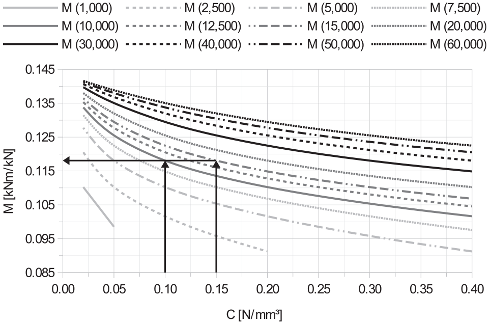
Moment stress at rail seat as a function of the modulus of elasticity, investigation case GEA (AM500, 260 mm × 160 mm, l0 = 2600 mm).
In addition to providing a large number of results, an extra added value should be generated. The aim was to bring the collected data into an overall context. This should enable statements about further cases that were not part of the investigations. Different approaches were used to process the collected results. As can also be seen in Figure 14, a coinciding ratio of modulus of elasticity and modulus of subgrade reaction leads to a matching bending moment.
Consequently, one approach investigated was to plot the results using this ratio. Figure 15 shows the corresponding values or the resulting curves for sleepers of a length of 2600 mm and for dimensions of the cross-sections of 260 mm × 150 mm, 260 mm × 160 mm and 300 mm × 200 mm. The bedding with a 500 mm long support-free centre section and the loading by point loads were also taken into account also in this case. By using the ratio value, it was possible to display all the results of one investigation case with one curve. However, different curves resulted for the different cross-sections.

Moment stress at rail seat as a function of the sleeper cross-section, investigation case GEA (AM500, l0 = 2600 mm).
When investigating further variants, the evaluation of the bending moments as a function of the sleepers elastic length L (equation (3)) provided the best result. The elastic length was determined using the actual sleeper width. In this way, depiction of all data of one support condition could be done by means of one function graph. A differentiation between the various cross-sections was no longer necessary. Figure 16 shows the moment curves for sleepers with a length of 2600 mm. The visualisation shows the results of all three support variants under loading by point loads.

Moment stress at rail seat in relation to the elastic length L for sleepers of constant cross-section with loading by point loads (l0 = 2600 mm).
In this way, a generally valid basis was created for determining the moment stress of sleepers of constant cross-section with loading by point loads.
In addition, the results of the calculations with loading by line loads were subjected to an analysis. In a direct comparison of the results, no parallels could be found initially. By taking the results of the loading with point loads into account and adapting the approach, a correlation was established. For this purpose, the moments had to be converted into lever arms first. For the bending moments at rail seat, the system simplification according to Figure 17 was used. In this case, a constant and symmetrical distributed bedding reaction has been supposed. Consequently, the resulting forces of the support were assumed to be equal to half the resultant of the line load or equal to the resultant of half the line load.

System simplification for determining the lever arms, bending moment at rail seat.
Accordingly, the lever arm a was obtained by dividing the bending moment by half the load resultant R. For the loading with point loads, the lever arm was determined by dividing the bending moment by half the point load F. This has been implemented by doubling the moments, since no numerical consideration of the load was made at the calculations.
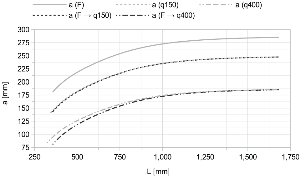
Figure 18 shows the lever arms determined in this way for the case of loading with point loads and for all cases of loading with line loads. The visualisation shows the values for a sleeper length of 2600 mm for a supporting with a 500 mm long support-free centre section.

Lever arms a for determining the moment stress at rail seat in relation to the elastic length L for sleepers of constant cross-section (AM500, l0 = 2600 mm).
By reducing the lever arm of the load case point loads (aF), the lever arm of the load case line loads could be approximately obtained. For this purpose, the lever arm was decreased by the distance between the resultant of half the line load and the point load. This distance resulted in 1/4 of the load introduction length lq (Figure 17). During implementation, differences between the lever arms were noted, as Figure 19 shows.
Result of the adjustment of the lever arm a by ¼ of the load introduction length lq in relation to the elastic length L.
By introducing a correction factor ka, the deviations could be compensated. In order to achieve the best possible adaptation, this factor was defined section by section as a function of the elastic length L of the sleeper. Using equation (7), it was possible to determine the resulting lever arm ares.

Figure 20 shows the result of the corrected lever arm determination.

Result of the adjustment of the lever arm a with inclusion of the correction factor ka in relation to the elastic length L.
Furthermore, it was necessary to determine the lever arms for the moments in sleeper centre. For this purpose, the system simplification according to Figure 21 had been applied. Due to the assumption of a constant and uniformly distributed bedding reaction, the resultant of the bedding was to be set equal to the resultant of the line load. The lever arm m could therefore be determined by dividing the bending moment by the resultant of the line load R. For the loading with point loads, the lever arm had to be determined by dividing the bending moment by the point load F. Since no numerical consideration of the load was made in the calculations, the lever arms were to be equated with the moments.

System simplification for determining the lever arms, bending moment in sleeper centre.
Figures 22 and 23 show the lever arms for the case of loading with point loads and for all cases of loading with line loads. The visualisations show the values for a sleeper length of 2600 mm with a 500 mm long support-free centre section as well as with full-surface support. Lever arms of negative bending moments are given a negative sign and lever arms of positive bending moments are given a positive sign.
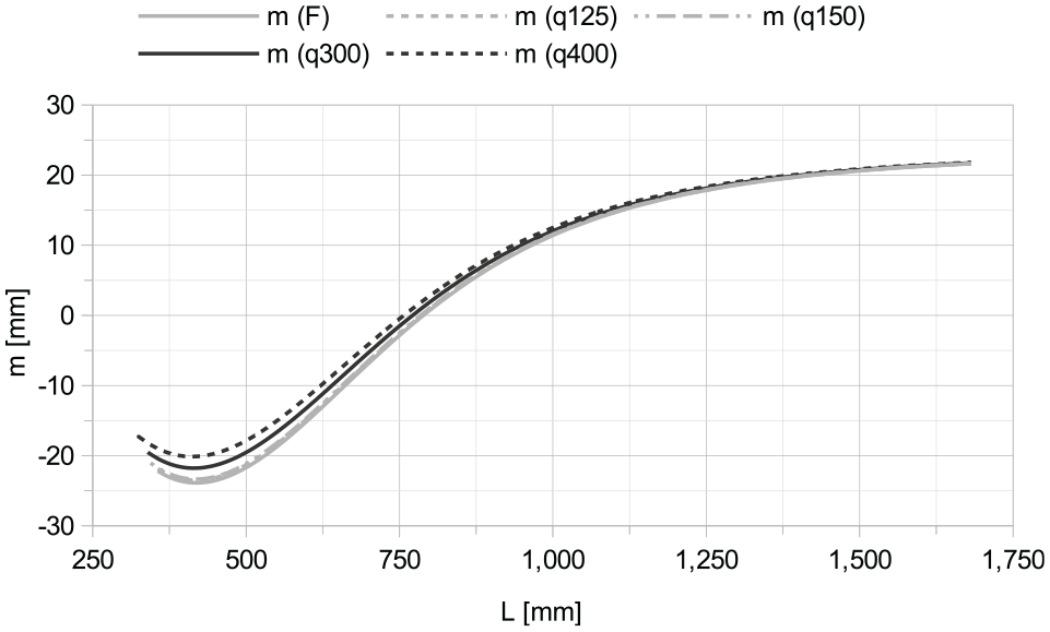
Lever arms m for determining the moment stress in sleeper centre in relation to the elastic length L for sleepers of constant cross-section (AM500, l0 = 2600 mm).

Lever arms m for determining the moment stress in sleeper centre in relation to the elastic length L for sleepers of constant cross-section (VL, l0 = 2600 mm).
The full-surface support was decisive for the maximum negative bending moments in almost all cases. In this context, virtually no deviations in the lever arms showed up between the loading cases point loads and line loads. When considering the lever arms in the case of supporting with a support-free centre section, there were also only minimal differences. Since the deviations were small in all cases and the load case point loads provided the maximum lever arm values in terms of amount, these differences were neglected as being on the safe side. Accordingly, the resulting lever arm could be chosen equal to the lever arm of the load case point loads (mF).
Conclusions and outlook
Thanks to the explained procedure, it was possible to determine the lever arms independently of the load introduction length. The results of the calculations with loading by point loads consequently formed the sole basis of the lever arm determination. In combination with the scaling of the results over the elastic length of the sleepers, this resulted in a generally valid, material-independent method for determining the moment stress of sleepers of constant cross-section, independent of the load introduction length.
The described method deals with the determination of bending moments but does not address further influences to be considered regarding the sleeper stress. In practice standard, exceptional and accidental loads occur. Additional influences result from support irregularities or the installed superstructure material. To consider all these parameters, the implementation of the new method to a verification procedure, incorporating the beforementioned as well as supplementary influences, was proposed. All information regarding this procedure can be taken from the dissertation ‘Development of a material-independent verification procedure of railway sleepers’. 1
Another potential field of application for the new method is the determination of the moment stress of slab track elements. For sleepers of other lengths and other gauges, the creation of a database and the elaboration of the associated curves and diagrams is easily possible.
Figure 24 shows an example of the lever arm curves for determining the moment stress at rail seat of a sleeper with a length of 2600 mm. This and all other illustrations of the lever arm curves can be found in the appendices of the dissertation ‘Development of a material-independent verification procedure of railway sleepers’. 1

Lever arms a for determining the moment stress at rail seat in relation to the elastic length L for sleepers of constant cross-section (l0 = 2600 mm).
In addition to the calculations explained in detail, the mathematical application of a prestressing force was also investigated. By comparing the results with those of a sleeper that was not prestressed, it could be shown that a consideration without prestressing results in identical or higher stresses. For this reason, the focus of the investigations was placed on the case without consideration of a prestressing force.
It is needed to be brought up that the whole investigation was premised on a theoretical base. Experimental validation of the data or the resulting method was not contained in this study. For a prospective research project this open aspect should be considered.
Nonetheless, the described procedure can be transferred in an identical way to the results of the calculations for sleepers of variable cross-section. In principle, such investigations were also carried out with the geometry of a sleeper of type B 70 sleeper. However, a link to the results of the sleepers of constant cross-section could not be established. The extension of the method to all sleepers of variable cross-section is therefore a task that still needs to be solved. Further research will be necessary in this context.
Footnotes
Handling Editor: Chenhui Liang
Declaration of conflicting interests
The author(s) declared no potential conflicts of interest with respect to the research, authorship, and/or publication of this article.
Funding
The author(s) received no financial support for the research, authorship, and/or publication of this article.