
Abstract
Simulation is an important tool to support rail decarbonisation but can be challenging due to heterogeneous models, simulation tools and skill sets, and concerns around intellectual property. Multi-modelling, a proven methodology in sectors such as aerospace and automotive, uses Functional Mock-up Interface (FMI) and co-simulation to potentially overcome these problems. This paper presents a feasibility study of multi-modelling for rail decarbonisation, using a combination of audit of current state of the art, technical implementation and stakeholder consultation. The audit showed that while current uptake of FMI in rail is low, there is potential to repurpose models from pre-existing tools and apply them within multi-modelling. The technical feasibility assessment demonstrated how multi-modelling could generate flexible simulation outputs to identify decarbonisation systems effects both for urban and mainline rail, including rapid integration of pre-existing MATLAB Simulink models. Work with industry stakeholders identified use cases where multi-modelling would benefit rail decarbonisation, as well as barriers and enablers to adoption. Overall, the study demonstrates the feasibility and considerations for multi-modelling to support rail decarbonisation efforts, and the future developments necessary for wider rollout.
Introduction
The railways have an important role to play in reducing global carbon emissions.1,2 Simulation is an important tool to design low carbon rail systems and to predict carbon impact. 3 System-level simulation can be difficult, however, due to challenges in integrating multiple models from multiple tools and in diverse formats.4–6 There may also be concerns around models and data revealing Intellectual Property (IP) of suppliers.7,8
Multi-modelling offers a solution to address this simulation challenge.9,10 Multi-modelling is the application of two, complimentary technologies – Functional Mock-up Interface (FMI)11,12 and co-simulation. 13 FMI is a standard format, widely adopted in sectors such as automotive and aerospace [e.g.14–17] that enables the packaging of simulation models in the form of Functional Mock-up Units (FMUs). Multiple FMUs can be run together in parallel through a co-simulation toolchain. 18 This toolchain supports the interfacing and synchronised execution of qualitatively different model types – including both discrete event and continuous time – to generate and visualise complex simulation results. Together, FMI and co-simulation has the potential to deliver complex system simulation in a more flexible manner than currently possible through traditional rail simulation methods, but is an unproven technology for rail decarbonisation.
The following paper presents an investigation into the feasibility of multi-modelling to support systems simulation for rail decarbonisation. This investigation had three objectives
to assess the current level of adoption of multi-modelling to address decarbonisation problems in the rail sector. This involved an audit, through literature review and discussion with industry representatives, of pre-existing simulation and tools for rail decarbonisation applications; to evaluate the potential of multi-modelling to support decarbonisation. This was assessed through a technical implementation of system simulations using both bespoke and third-party MATLAB Simulink source models, and the INTO-CPS co-simulation engine
19
; the challenge of rail innovation is as much about understanding the potential applications, value and acceptance from the rail sector, as it is about the technical challenge.
20
To that end, work with rail stakeholders with knowledge of systems modelling and/or decarbonisation elicited example use cases, and identified barriers and enablers. This was supplemented with interviews with experts in multi-modelling from outside of rail to understand how other sectors have successfully adopted the approach.
The contribution of the paper is therefore an audit of the state of application of FMI in rail, an evaluation of whether FMI and co-simulation can support rail decarbonisation, and guidance on successful future adoption, both for decarbonisation and potentially to other rail applications such as performance. This paper is orientated towards researchers and practitioners working in rail simulation, systems modelling and rail decarbonisation. We also hope it is of interest to the wider multi-modelling community, encouraging them to engage with rail decarbonisation efforts as a fertile area for work.
Background
The decarbonisation challenge
The Paris Agreement sets out a framework to limit global temperature rise this century below 2 °C above pre-industrial levels, and to pursue efforts to limit the temperature increase to 1.5 °C. 21 Transport is a significant aspect of this challenge, contributing around 20-25% of emissions, 22 of which 25% is generated in urban environments. 23 Policy and strategy are in place to drive rail’s contribution to decarbonisation through mechanisms such as local and regional commitments to rail (e.g., 24 national level policy and strategy to decarbonise rail (e.g.1–3,25 and international commitment to mode shift and rail electrification (e.g. 26 ) The aim is to both encourage rail travel as a mitigation of private vehicle emissions, and to lower the emissions of rail travel itself.
Electrification is a major part of decarbonisation. Electrified rail has 60% lower carbon emissions than diesel, rising to 90% with an estimated 2040 grid mix. 1 In addition, batteries27,28 can extend networks or close gaps in the network as part of discontinuous electrification strategies. 29 Hydrogen technologies30,31 have also been demonstrated to have substantial benefits to low carbon transport, without the potential capital costs of electrification. Power performance may be further improved through techniques such as driver advisory29,32,33 or timetable optimisation for energy efficiency. 34 Finally, decarbonisation can be considered not just in terms of rolling stock but also in terms of power usage and construction for infrastructure and assets,3,23 and across the asset lifecycle.35,36
The systems simulation challenge
While adaptation of individual components or subsystems can deliver decarbonisation benefits, these benefits can be amplified when coupled at a system level to maximise energy efficiency. Conversely, benefits can be negated through unanticipated system interactions.37,38 As an example, while it may be possible to re-charge batteries during turnarounds in duty cycles, this needs sufficient time in the timetable to allow the transfer of sufficient charge, which may vary due to seasonal factors such as weather or use of the Heating, Ventilation and Air Conditioning (HVAC) sub-system. The challenge is therefore to predict system interactions to support informed decision making for design and operations.
Effective modelling of decarbonisation is an identified research priority for rail decarbonisation. 3 Typically, rail components and processes have associated simulation models, used for design or optimisation. For rail power optimisation this could include equipment models from traditional rail suppliers such as models of rolling stock components and subsystems, dedicated models for power optimisation, for example to configure power efficient infrastructure (e.g. MERLIN – http://www.merlin-rail.eu/), and models from non-traditional suppliers to the rail sector (e.g. providers of sustainable energy 39 )
Simulation models may be thought of as dynamic in that they express behaviour that changes over time. Coupled together, their interactions may lead to complex, non-linear outcomes. Achieving this coupling can be challenging. Simulation models are likely to have been built at different times in diverse formats for different purposes 6 and do not integrate readily to give the whole systems view required for decarbonisation. Models may be bespoke to particular suppliers, who also have concerns around the sharing of models, data and Intellectual Property (IP). 8 These problems may be exacerbated when suppliers are new to the rail sector, such as the transfer of automotive lightweighting approaches to rail. 40 Typically, models from outside of rail conform to the standards and discipline norms of their domain, and lack contextual expertise of rail.20,41 The challenge, therefore, is to provide a flexible, open environment where diverse types of model and data can be combined and run in parallel to identify whole-system dynamic properties, while lowering overheads for new entrants.
Multi-modelling, FMI and co-simulation
Multi-modelling supports the integration of multiple models linked in parallel, while still existing in their native form.18,42 Numerous simulations can be linked together. This includes simulations that are qualitatively different - discrete-event models (simulations that are described as specific steps or events, such as how an operator responds to different inputs) and continuous-time models (typically, simulations that are expressed as mathematical equations, such as electrical or physical phenomena). This enables simulation of complex interactions and system effects between components.14,18 The Integrated Tool Chain for Model-based Design of Cyber-Physical Systems (INTO-CPS) technologies are a collection of tools that enable multi-modelling 18 (see Figure 1). The INTO-CPS technologies are an open tool chain, maintaining a commitment to open source where possible and therefore lowering the barrier to modelling and simulation, providing an alternative to commercial software from large vendors that could lock companies into using a single supplier.
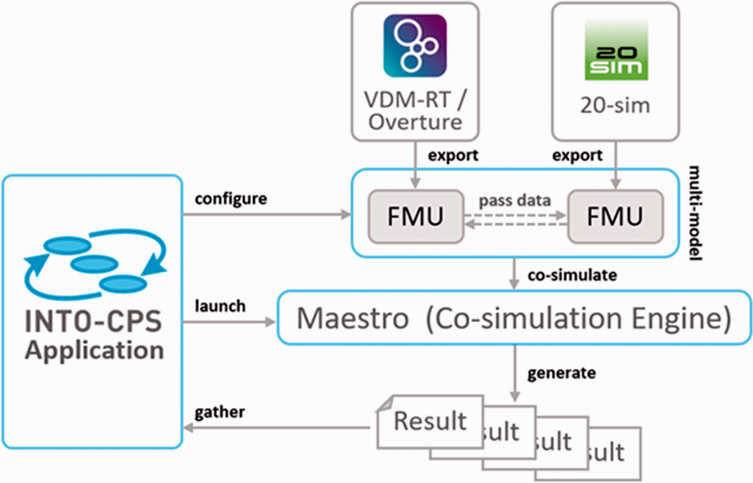
INTO-CPS co-simulation engine (see 18 ).
A key element of the openness of INTO-CPS is the adoption of the Functional Mock-up Interface (FMI) standard for co-simulation. 11 The FMI standard originated in the automotive domain to connect models—packaged as Functional Mock-up Units (FMUs)— to be simulated together (see 16 for more detail). A collection of FMUs representing the system are simulated together under the control of a co-simulation engine, which manages the passage of time and transmission of data between the FMUs. INTO-CPS is one such tool chain, providing an FMI-compliant co-simulation engine called Maestro. 19 Co-simulation results are generated and managed within Maestro, with the INTO-CPS Application providing a graphical interface to configure, run and inspect co-simulations. Critically, FMI means it is not necessary to completely describe the whole model within INTO-CPS. Instead, only the relevant inputs and outputs of each model are exposed, through the FMU, while the model inside can be encrypted. This is vital in sectors where suppliers wish to protect the intellectual property of the constituents of their models and the products they represent (e.g. how a battery achieves its performance).
Over 30 tools can produce FMUs (https://fmi-standard.org/tools/). This study used the discrete-event modelling language VDM-RT (Vienna Development Method—Real-Time dialect), an object-oriented modelling language supported by the Overture tool.43,44 Continuous-time models were implemented in 20-sim. 45 20-sim is a modelling tool that supports definition and simulation of continuous-time phenomena described through differential equations. These equations can be input directly and represented graphically using blocks and connections or through bond graphs, a domain independent notation for describing physical phenomena.
INTO-CPS and the Maestro co-simulation engine were selected because they are open-source and therefore easy for others to access. Maestro also supports a range of platforms (Window, Linux, OSX, Raspberry Pi). The benefit of FMI is that INTO-CPS and Maestro could be replaced by any FMI-compliant co-simulation engine, including open platforms such as CosiMate, and proprietary support in commercial software such as Dymola and Matlab Simulink.
The INTO-CPS tool chain includes a variety of other analysis techniques, including test-case generation and simulation with real signals from hardware (for more see 18 )
Successful applications of INTO-CPS include using multi-modelling in the development and optimisation of a steering system for a driverless industrial-size lawn mower. 16 Initial models of the kinematics, dynamics and steering control system were co-simulated to investigate the performance of the controller in a virtual setting. 46 demonstrate the use of multi-modelling for the design and validation of a robotic assembly line combining models including the robot arm, warehousing, part tracking, production and order-scheduling human–machine interface. 47 applied the approach to combine models of both the cyber and physical aspects of an emission reduction system for a two-stroke engine. 48 use multi-modelling to study human performance implications in multiple UAV control by modelling the impact of different operator responses under variable workload conditions. Multi-modelling has also been successfully used to support digital twinning. 49 However, at the start of this project there were no known applications in rail, despite the potential. 50
Adoption and impact
The first benefit of the multi-modelling approach arises if the system of interest includes multiple domains, such as complex cyber control alongside mechanical or electrical systems, and thus require the use of diverse simulation models, and prepared by several different modellers. Multi-modelling allows each part of the system to be modelled by domain experts using the most appropriate tools, and then be brought together to form a simulation of the system as a whole.
The second benefit occurs if there are multiple organisations involved in the development of a system and where those organisations do not wish to share the internal details of their models for IP or commercial reasons. Here the organisations can choose to share only the compiled, executable models with each other, rather than the original model source files. In this way the only part of the model revealed is its interface, and internal details are protected.
The third benefit is that models can be adapted and combined in multiple ways. In some cases, it may be possible to include multiple instances of a model (e.g. to have multiple FMUs of multiple UAVs flying at the same time 48 ) In this way, it is possible to conduct rapid Design Space Exploration (DSE) of a given systems problem.
The challenges, however, of adopting innovation of this kind are more than technical. 20 There also needs to be an understanding of the organisational and business appetite, and any technology development must be rooted in clear and meaningful use cases that meet a real decision making need to achieve decarbonisation efforts. Any solution for collaborative modelling must identify value and enabling factors, while also identifying and mitigating barriers to adoption such as concerns over IP. There are, however, challenges with levels of competency in areas such as simulation modelling, particularly outside of specialist teams or with partners/suppliers who may have little knowledge of simulation process. 20 Additionally, there can be challenges of coordination and knowledge exchange when working across organisational boundaries. 51 Smaller suppliers may have limited skills or access to simulation software. 52 Collaborative simulation must be treated as not just a technical, but a socio-technical problem. 41 Therefore, any potential deployment of technology should anticipate and design for the organisational, and inter-organisational context, that is likely to be found in rail decarbonisation.
Audit of current state of FMI in rail
While multi-modelling has been used successfully in other domains, it was unclear at the outset of this investigation if there were any applications in rail decarbonisation, and rail systems generally. A pre-existing set of FMI compatible models could be used to test the integration of simulation using INTO-CPS (discussed in the Technical evaluation section), and give indication of rail sector awareness and appetite for FMI and co-simulation. The first objective was therefore to understand level of adoption, if any, of FMI in rail.
Method
An audit was conducted, using three approaches: -
Step 1 - State of the art review –Scopus, Web of Science and Google Scholar were searched using terms (“Functional Mock-up Interface”) and (“Rail” or “train”). Relevant papers were listed and reviewed
Step 2 - Consultation with industry stakeholders to understand what adoption or awareness there might be of multi-modelling in the rail sector (this consultation is covered in greater depth in the Use cases, barriers and enablers section).
Step 3 - Tool review – In response to very few tangible applications of rail FMI in state of the art review and industry consultation (Steps 1 and 2), an alternative approach was taken. This involved an audit of a list of FMI-compliant simulation tools 53 to identify if any of these tools had been used for rail applications. This covered generic simulation tools, as well as specific tools relevant to domains such as power trains (e.g. Virtual Engine). While FMI may not have been applied, as yet, for significant rail applications, it might be possible to rapidly adapt simulations built with compliant tools into FMU. The tool search was conducted in general Google (to identify industry application) and Google scholar, using a search term of “[Tool name] and (‘rail’ or ‘train’)”. Tools were then graded in terms of whether they generated ‘strong’ results (several tangible implementations of rail-relevant simulation), ‘weak’ results (discussing general applicability or potential of the tool to rail, but no specific implementation) or no results.
Results
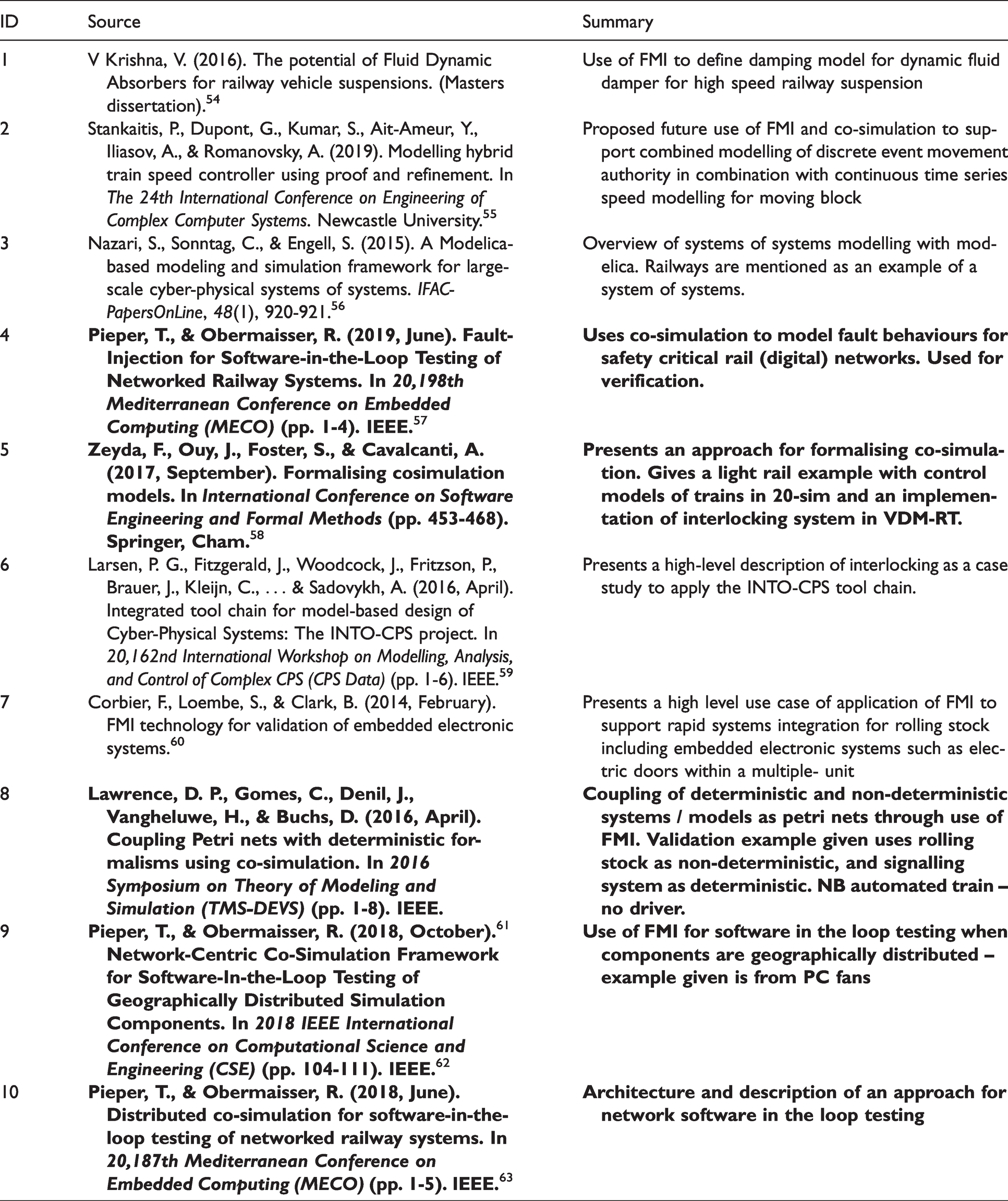
Neither Scopus and Web of Science returned any academic research on rail and FMI. A Google Scholar search, with less stringent filtering, returned 10 potential papers, listed in Table 1.(54–63) Of these, five were relevant to rail and FMI, of which three came from the same EU Shift2Rail project (Safe4Rail)54–56,57,62,63 (the other two papers are57,58,61) No papers covered rail decarbonisation applications. A general (non-Scholar) Google search identified one research project at the German Aerospace Research Institute (DLR) on simulation based design, though there were no available project outputs (https://www.dlr.de/sc/en/desktopdefault.aspx/tabid-11174/19594_read-45605/).
In terms of stakeholder feedback (for more detail, see the Use cases, barriers and enablers section), there was some awareness in the rail sector of FMI and its potential, particularly from simulation and systems modelling specialist, and from stakeholders who were also aware of developments in sectors such as automotive. There was, however, only one reported instance of FMI being used. This was a project conducted by Prorail but no further information was available.
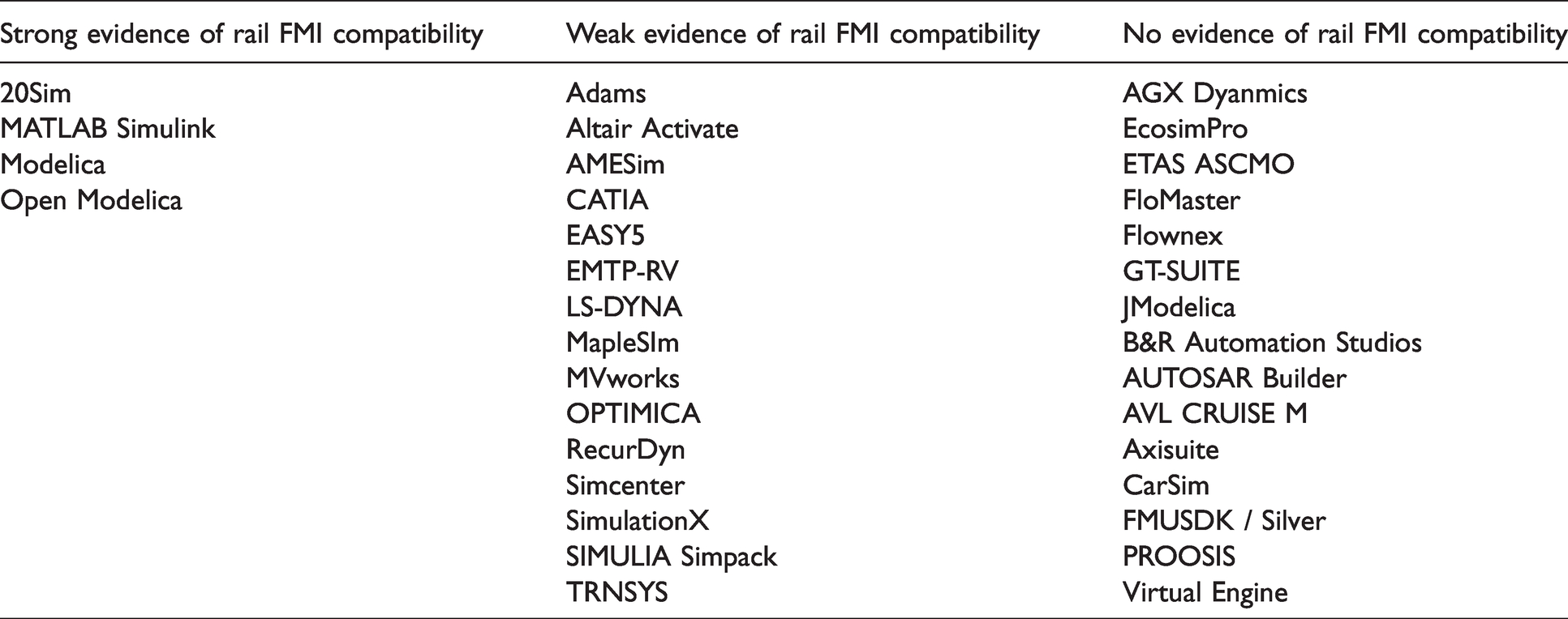
Of the tools surveyed, strong examples of rail applications could be found for 20-sim (e.g. 64 ) MATLAB Simulink (e.g. 65 ) and Modelica/Open Modelica (e.g. 66 ) A summary of the survey is presented in Table 2. Overall, these results indicate that while FMI and FMU is not widely adopted, the types of models currently being used in rail simulation, including decarbonisation applications, would be amenable to integration via FMI into multi-modelling.
Evidence of compatibility of FMI tools to rail applications.
Technical evaluation
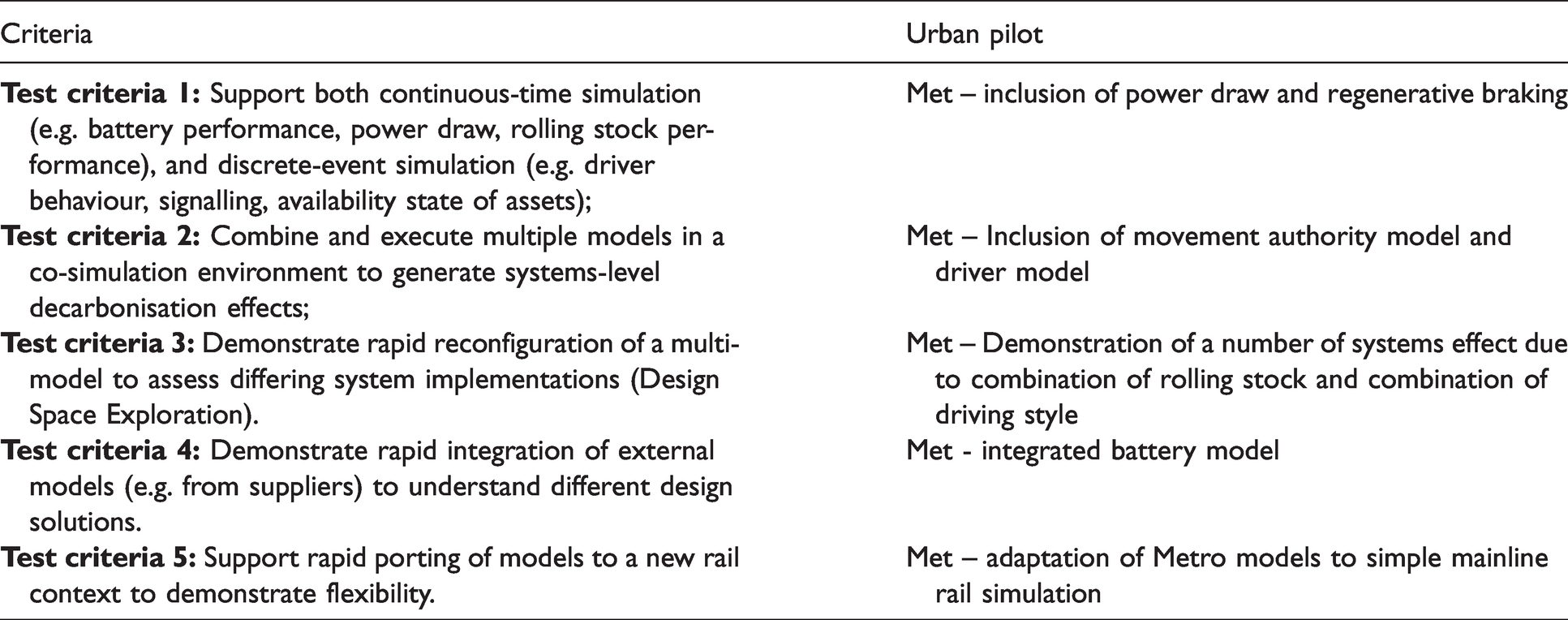
To assess whether multi-modelling was able to address the challenges of systems-level decarbonisation modelling, the following test criteria were defined:
Based on the experience of the team in both rail and in use of FMI in other domains, these test criteria would indicate that FMI and multi-modelling was capable of delivering insight into typical decarbonisation problems in both light rail and mainline.
Method
The test criteria were evaluated through a five-stage process.
Step 1 – Defining multi-model
The pilot context that served to generate the initial modelling was taken from the Tyne and Wear Metro. 70 The Tyne and Wear Metro provides a major transportation network into the cities of Newcastle upon Tyne and Sunderland and the surrounding urban and suburban areas. Rolling stock is powered by 1.5-kv overhead electrification. Metro has previously served as a testbed for modelling and more general urban rail research.68,69 The specific location selected for modelling was between South Gosforth and Ilford Road station. This approx 1 km section is on the core of the metro network, with short service headway during the peak (around 30 trains per hour). It is also one of four track sections previously studied in 68 and thus provided data both for rolling stock and for validation. This included weight, velocity, power consumption, braking performance and drag.
The simulation assessed how carbon output might vary as a result of both traction type, and driving style as is typically observed when drivers have engaged in ‘defensive’ or ‘energy efficient’ driver training. Additionally, the simulation looked at two trains in combination to understand the potential interactions (i.e. systems effects) that might emerge due to limited headways.
The multi-model was designed around four FMUs.
Train model – models the behaviour of the train in response to the actions of the driver model. The train also draws power from the power model and can pass power back to the power model in a regenerative configuration. Two instances of the train model were required for the simulation. Power model – models the availability of power to trains. The design also supports receiving power from trains in a hypothetical situation where trains pass regenerative power back to the network. Movement authority model – models the state of the signalling system for a specified area of the network, including interlocking, and passes signal state to the driver. Driver model – models the actions of the driver (apply power, apply brake) in response to movement authority and passes state to the train model. Two driver models (one per train model) were required for the simulation.
Figure 2 shows the structure of the multi-model.
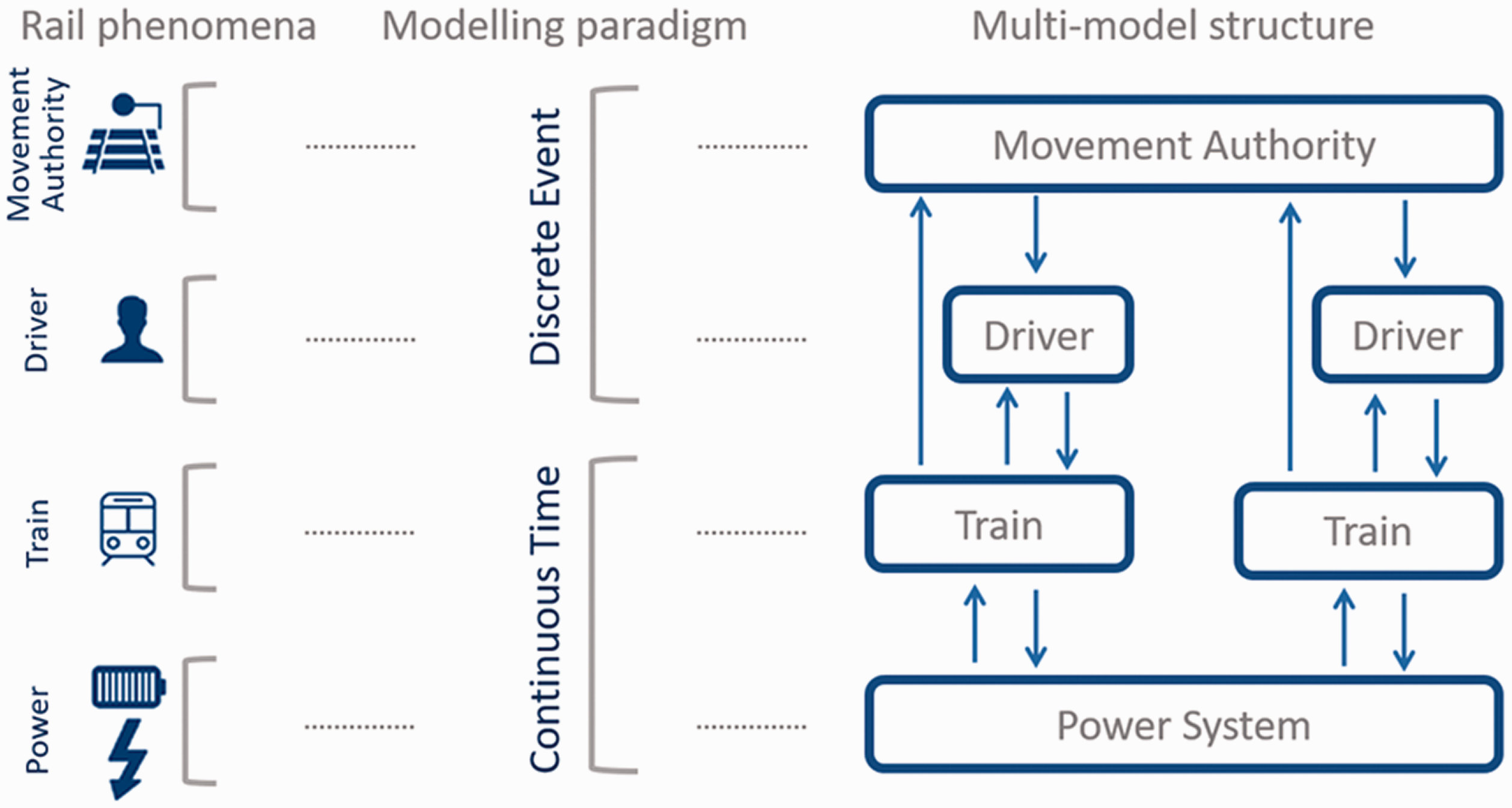
Basic conceptual multi-model of a rail system.
Step 2 – Defining source models
Having defined a structure for the multi-model, four source models were developed. As an example, Figure 3 shows the train FMU. This comprises a number of continuous-time sub-models built in 20-sim adapted for light rail from.68,69 The power supply model was developed as a continuous-time model in 20-sim. The power FMU has outputs providing line voltage to the train FMUs and receives inputs yielding how much power the trains use. The movement authority model represented the state of the signalling system based on the signalling infrastructure between South Gosforth and Ilford Road on the Tyne and Wear Metro system. This is a discrete event model implemented in VDM that represents basic two aspect signalling with an interlocking. The driver model is also realised as a discrete event simulation in VDM. The driver model receives input from the movement authority in the form of the state of the next signal on the track. The model also receives input from the train model giving the position on track and the speed. The driver model decides whether to proceed or brake as required, based on the state of the next signal, and distance from it (e.g. slowing down ahead of a red/stop aspect). Further details on the models are available in. 67
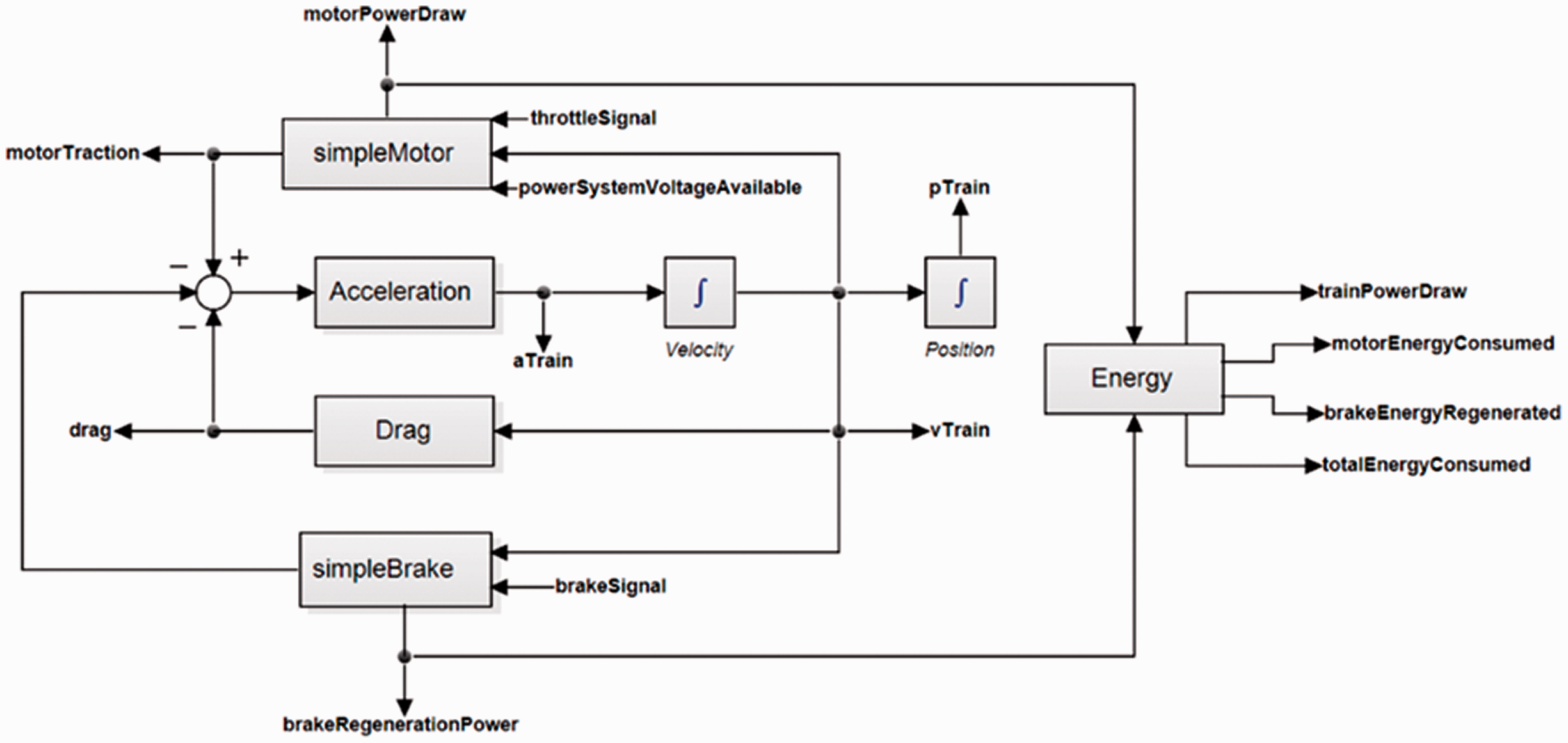
Structure of train sub-model.
In order to enable DSE, two versions of the train model were developed; a standard model based on the Metro rolling stock current characteristics, and a power optimised version, which was light-weighted (from 40 metric tonnes to 35 metric tonnes) and with regenerative braking sub-model. The driver model was also developed in two variants – a baseline driver, and a ‘defensive’ driver – a driver who was slower in applying power and brake, as is typically exhibited in more energy efficient driving.
Step 3 – Running the model
The INTO-CPS application was then used to orchestrate the FMUs and define the number of instances of each model required for the scenario.
In order to assess the potential for design space exploration, four variants of the multi-model were created:
2 baseline drivers with standard rolling stock 2 baseline drivers with power-optimised (lightweight + regenerative braking) rolling stock 2 defensive drivers with standard rolling stock 2 defensive drivers with power-optimised (lightweight + regenerative braking) rolling stock
Step 4 – Inclusion of third-party model
A third-party model was added to the multi-model described above using models from OPEUS, 71 a tool for power optimisation of rail systems. OPEUS comprises a library of models built using MATLAB Simulink, identified at the audit stage as an FMI-compliant simulation tool with significant current adoption in the rail sector.
For this test, the OPEUS battery model was selected from the Energy storage system library. Simulink supports FMU export in ‘tool wrapper’ form as of version 2019a (add-ons are available for previous versions). This method requires that the computer running the FMU during a co-simulation has a valid MATLAB license. Simulink also supports export of a model as C code, which can then be compiled and wrapped as a ‘source code’ FMU. Creating source code FMUs is provided by several third-party tools, including FMI Kit and Simulix. The latter was selected for this test, because this produced a smaller FMU and is more in keeping with the spirit of sharing as the FMUs produced are self-contained. The core interface of the Battery model is a power draw as input and a voltage as output, and thus the Battery FMU was linked into the urban rail multi-model as a straight swap for the Power FMU.
Step 5 – Transfer to mainline
The multi-model and source models from the urban rail context were then adapted for a representative mainline context. To do this, the following adjustments were made to the train model. Parameters were based on a 5-car Hitachi Class 800 as used on Great Britain’s East Coast Mainline. Maximum speed was adjusted to 60 m/s, approximating 134 mph. The mass of the vehicle was adjusted to 243 tonnes. Additionally, the movement authority model was adapted to represent a track length of approximately 20 km – the distance between Newcastle and Durham on the East Coast Main Line. The length of track was broken down into five equally spaced track sections each controlled by a signal. The movement authority model was developed to support four-aspect (green, double yellow, yellow and red) signalling rather than the simple two-aspect signalling system used on the Metro. The driver model was adapted to reflect this change, with a reduction to 20% of power at a double-yellow aspect, and an application of brake at a single yellow, leading to a stop at a red.
As an indication of the complexity and skill required, this step was performed by a developer with basic experience in simulation modelling. This step took around 50 days of efforts (not efforts) while the developer both updated the model while training in parallel on INTO-CPS.
Results
Table 3 shows the results of FMI implementation against the five test criteria.
Feasibility results.
Test criteria 1–3
Figure 4 shows the outputs for one run of the simulation – where both trains have been lightweighted (with regenerative braking) and with defensive driving. The figures show a number of outputs from the simulation run.
Metro system simulation. Clockwise from top left: train positions, driver model inputs to the simulation, cumulative energy consumptions, and train speeds for a single scenario (baseline driver and lightweight rolling stock).
Figure 5 shows the cumulative power consumption (combined Train 1 and Train 2) for each scenario on the left-hand axis. Power consumption was converted to carbon emissions by multiplying joules to carbon at a rate of 275 g per kWh 72 presented on the right hand axis. The lightweight and regenerative rolling stock, but with defensive driving scenario (orange broken line) offers similar decarbonisation benefits to defensive driving (grey line) in comparison with baseline rolling stock and aggressive driving (yellow broken line). The combined defensive driving and lightweight rolling stock offers (blue line) offers the best power performance, in terms of cumulative energy consumption. This is, however, at the expense of time (Train 2 arrives at its destination later, as a product of both trains being driven more defensively). This indicates the kind of dynamic interaction and systems trade-offs one would expect to see with multi-modelling. NB overall power consumption continues to rise, even towards the end of the scenario, as Train 1 is still on the move.
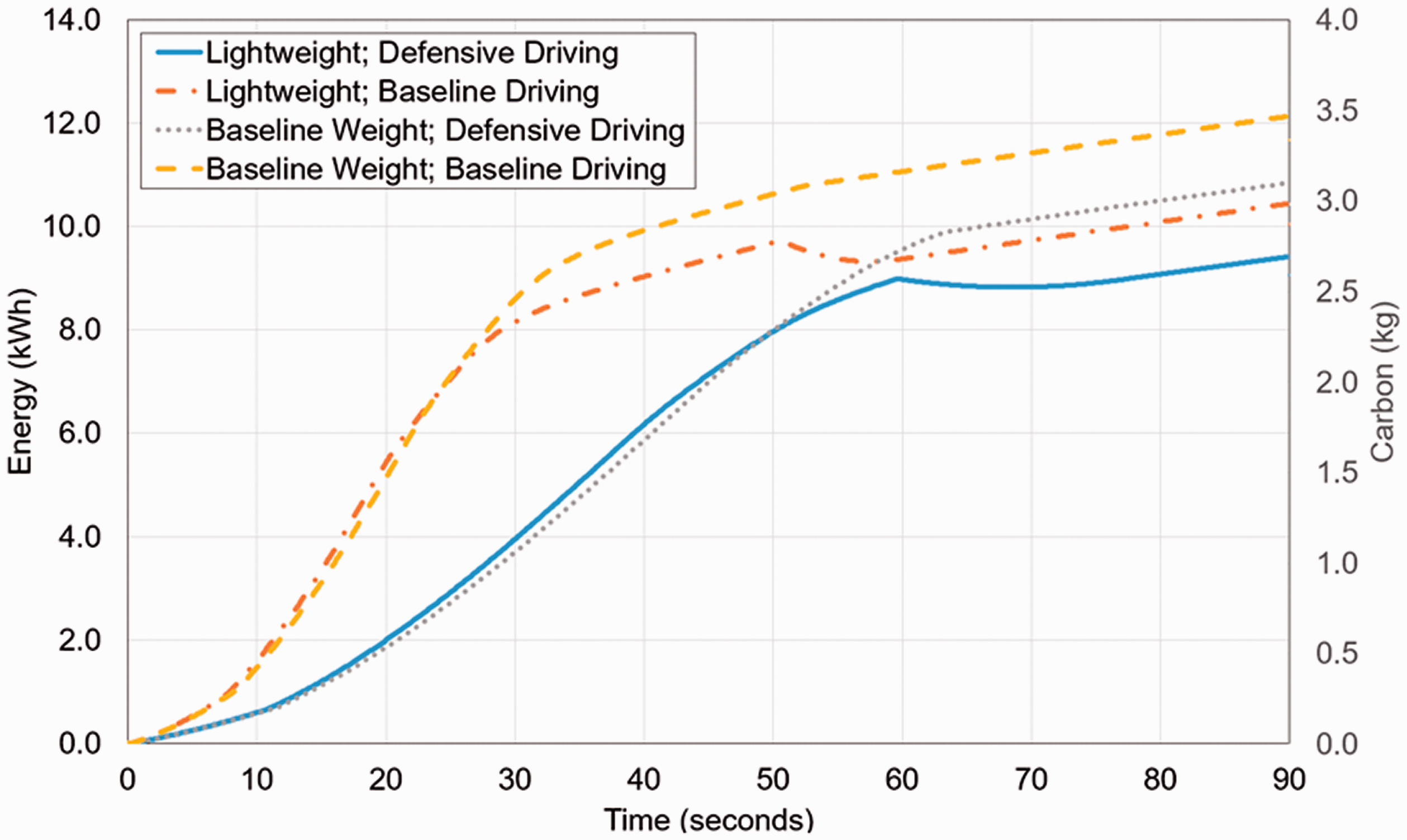
Energy (kWh) and carbon (g) used against time (seconds) for the four simulations.
Test criteria 4 – Integrating a third-party model
Figure 6 shows the results from a single co-simulation of the urban rail pilot incorporating the OPEUS battery as an FMU, as train speed and energy consumed. Both trains drive forward during the 80 second simulation and consume a small amount of energy from the battery. The line voltage in the original model was 1500 V while the battery produces 800 V, resulting in an underpowered Metro that moves slowly. This demonstrates that the battery is behaving in a manner that realistically effects the wider rolling stock system. While this may be operationally unrealistic for the context in which is being applied (e.g. for conventional operations between stations) there are potentially contexts where the battery could be useful even at low voltage, for example in depots, on infrastructure with limited clearance or access for OLE, or for a cheaper alternative than full electrification on slow line passing loops.
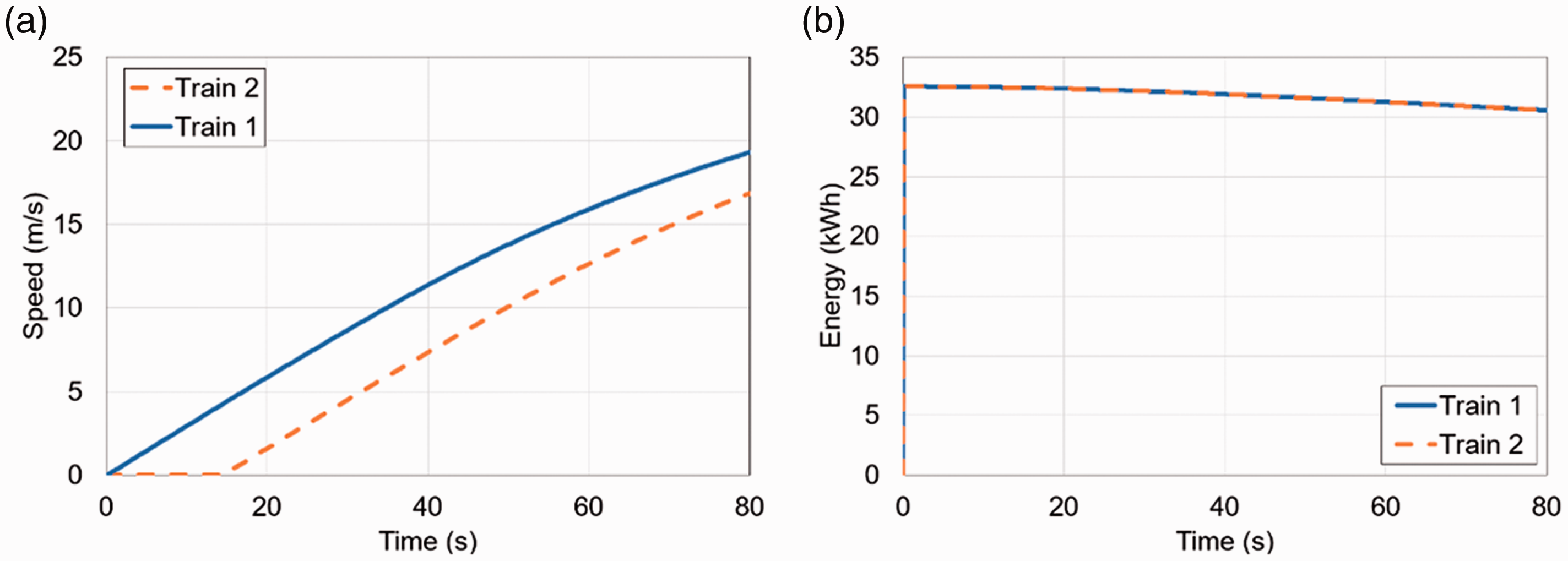
Co-simulation outputs showing the OPEUS battery FMU in the urban rail pilot (left to right – train speed and energy usage).
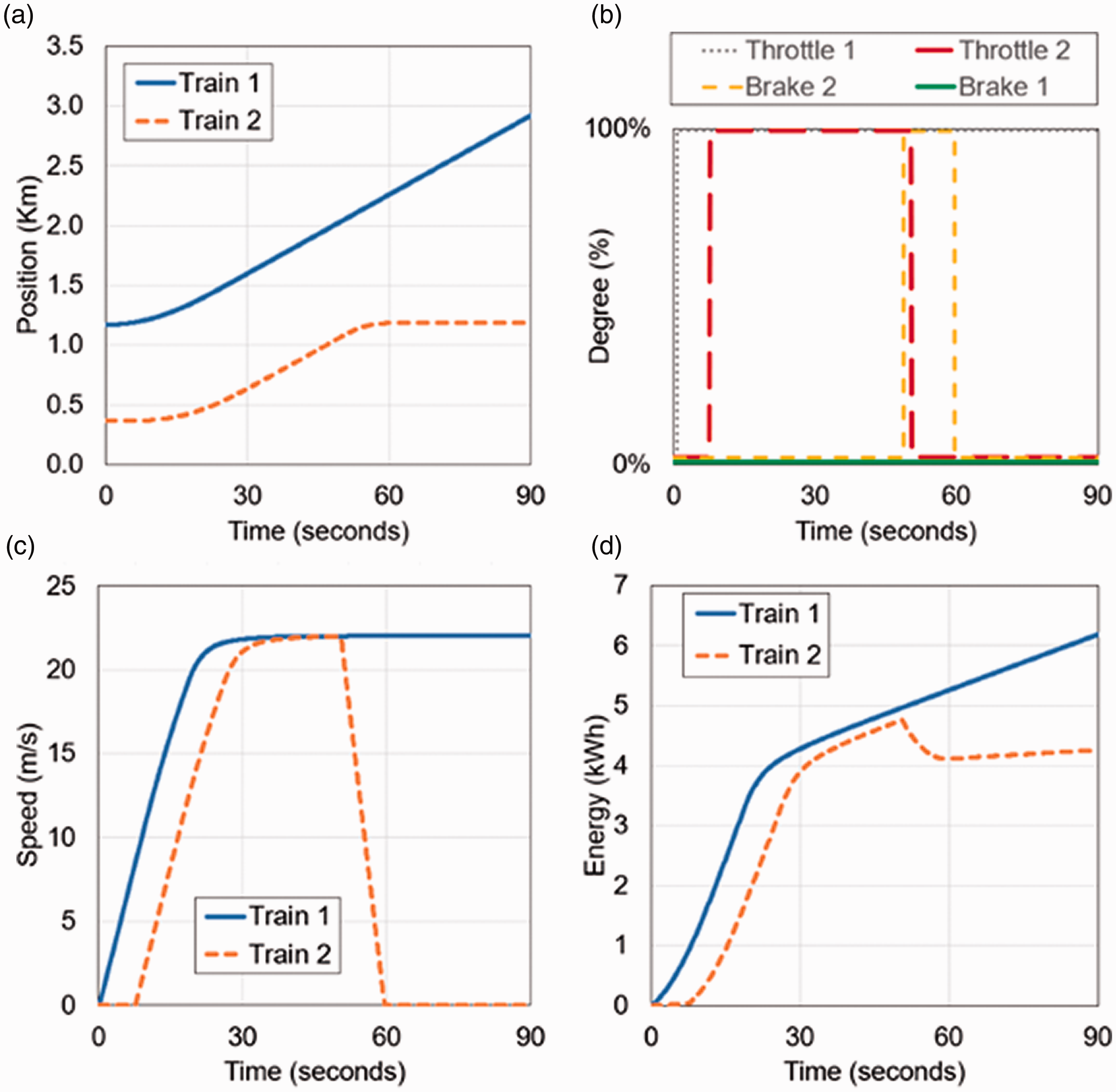
Step 5 – Adapting to mainline
Figure 7(a) to (d) show the modelling outputs for a run of a single train on the mainline scenario. Clockwise from top left: Figure 7(a) presents the position of the train over time, showing the acceleration and deceleration of the train at the beginning and end of the run. Figure 7(b) presents the outputs of the driver model. The driver applies power (blue line) before reducing to 20% power on approach to the cautionary aspect, and then applying brake (orange) to stop at the danger aspect, notionally at the end of the platform at Durham.
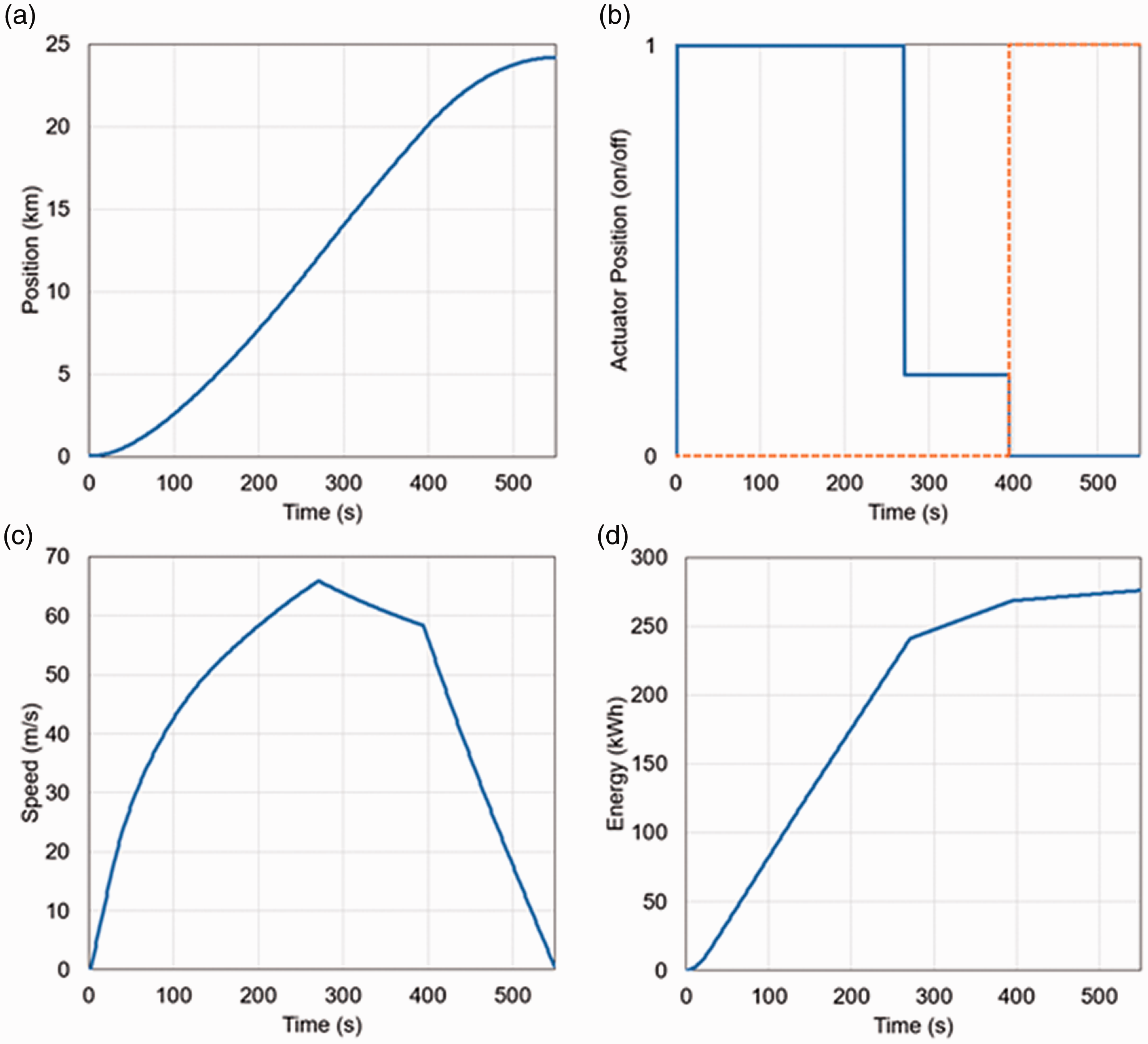
Mainline system simulation. Clockwise from top left: train position, driver model inputs to the simulation, cumulative energy consumption, and train speed.
Figure 7(c) presents power consumption, with linear consumption as power is applied, a lower rate of increasing consumption as the driver reacts to the cautionary aspect, and the power consumption dropping in response to the regenerative braking input when driver brakes in response to danger aspect. Assuming the conversion rate, as before, of 0.275 g of carbon per kWh, a journey distance of 20 km, and a load of 100 passengers, a total power consumption of 300 kWh equates to 40 grams of carbon per passenger per km, which is a reasonable result given the simplicity of the model. Figure 7(d) presents the train speed, approaching maximum speed before slowing after the drop in power due to the cautionary aspect, and then decelerating more rapidly as brakes are applied to stop for the danger aspect. Train speed reaches just over 60 m/s, or approximately 135 mph. While slightly high for a Hitachi class 800 on the East Coast Mainline, where maximum speed is 125 mph, this is broadly realistic. The models could be tuned to add line speed in the infrastructure, driver behaviour to adhere to linespeed, and to tune rolling stock to include a passenger load.
Use cases, barriers and enablers
Innovation can be challenging in any sector and railways are no exception. The rail sector has been highlighted in the past for lacking a systems perspective.73,74 It is also a domain where it can be difficult for non-rail organisations to have an impact. 20 Therefore, it was important not only to consider the technical feasibility of the multi-modelling approach, but also to consider the potential barriers and enablers that might impede or accelerate the integration of multi-modelling into rail decarbonisation work.
FMI and co-simulation are already well known and well applied approaches in other sectors, such as automotive and aerospace, and emerging as standard practice in areas such as robotics, digital twinning and maritime. It was therefore useful to talk to people with experience of FMI/co-simulation from other sectors, to understand what factors have encouraged adoption, and lessons learned.
Method
Discussions were held with a number of rail stakeholders. These included two interviews and workshops with members of the academic research community, and ten interviews or workshops with current and future operators, Small to Medium Enterprises (SMEs)s and Original Equipment Manufacturers (OEMs)s from the rail supply chains, infrastructure managers and steering bodies (e.g. cross-sector working groups). Across all organisations, discussion was held with those involved in rail systems, simulation, decarbonisation, data standards, and product design/engineering.
From this discussion, a number of potential use cases were identified that were both novel and valuable, in that they offered a potential contribution to rail decarbonisation efforts without duplicating pre-existing simulation tools. Each was then specified in terms of rail context, use case description, benefits and implementation status.
Additionally, interviews were conducted with five non-rail FMI experts from industry and academia. These experts worked in areas including maritime, aviation, automotive, agri-robots and FMI/co-simulation tool.
In all cases, discussions covered familiarity with FMI and co-simulation, utility of the multi-modelling approach, potential applications where multi-modelling would add value (i.e. use cases), and applications where it would not, and barriers and enablers.
Results
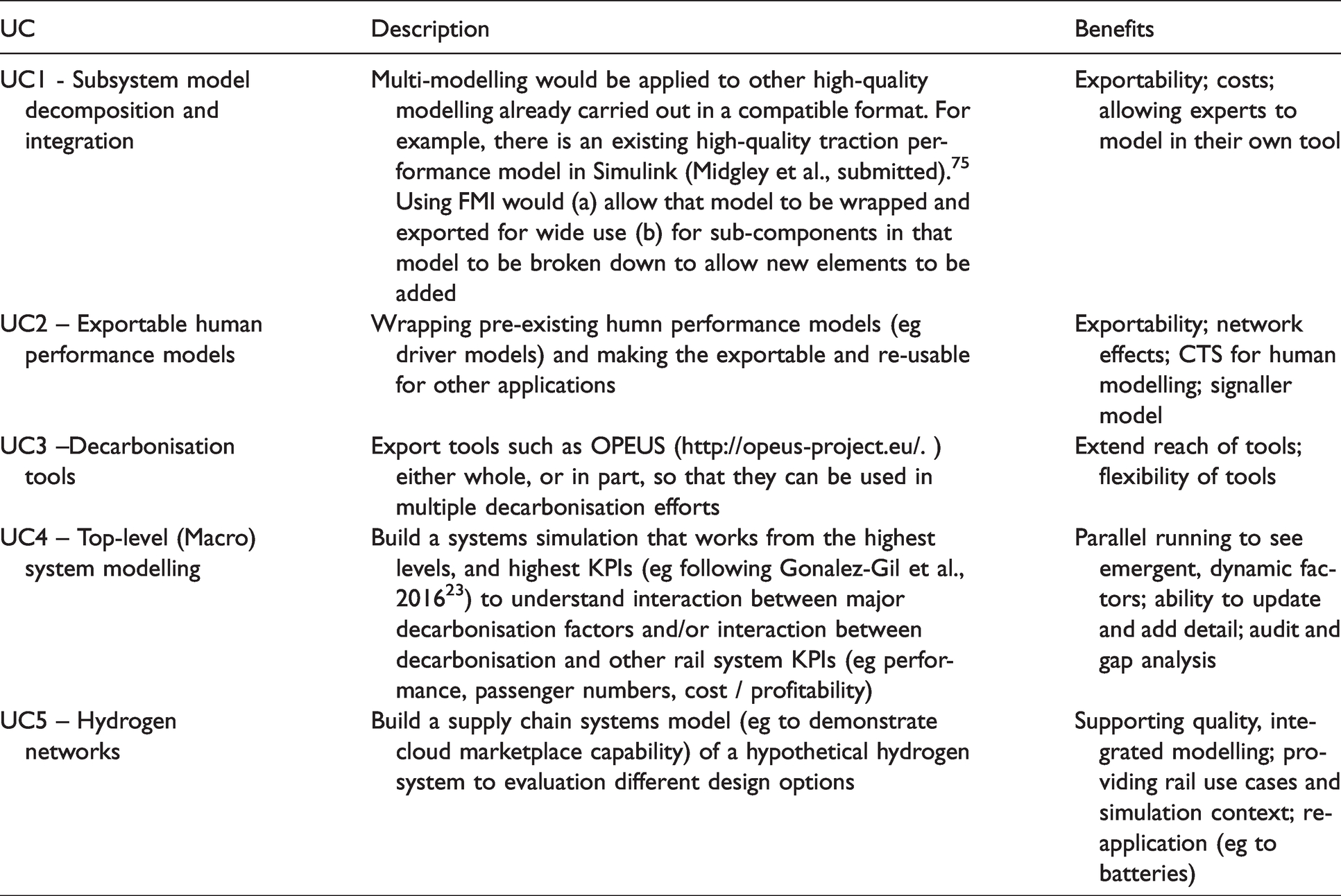
Use cases. Potential use cases came from across decarbonisation, including power design, rolling stock design, timetable for power optimisation, lineside renewables, and construction carbon. This supported the definition of five key use cases that are both tangible and can deliver value to the railsector in the short to medium term, presented in Table 4.
Summary of use cases.
Barriers and enablers
Feedback from rail sector representatives was as follows: -
Awareness of FMI was limited. Those with an awareness had an understanding of the potential value, and that they would benefit from knowing more about the FMI/multi-modelling approach, particularly with a view to understanding how other sectors (e.g. automotive) have successfully adopted FMI. Currently, complex system modelling tends to be applied to high priority/high value cases (e.g. power system design to match planned serice requirements for a route). Many of these models rely on legacy software, and it may be difficult to extend these models due to their bespoke nature. The barriers to FMI adoption, and collaborative or complex system modelling in general expressed by rail experts are those anticipated by the FMI multi-modelling approach – concerns lay around IP, models built in proprietary formats, and the activity of combining models being a resource intensive activity. Clarity is needed when presenting ideas around FMI and multi-modelling. Modelling in rail applies to a number of concepts and technologies – this could be carbon models which take the form of carbon calculators (e.g. the RSSB rail carbon tool), or data models which describe the structure and semantics of data.
74
Neither of these are directly addressed by multi-modelling, though both can help or benefit from multi-modelling efforts. Multi-modelling refers to simulation modelling – dynamic modelling of behaviours and performance, and descriptions of its relevance to the rail sector should be positioned as such. There are particular concerns around the quality of underpinning data that would be needed in multi-modelling efforts. In some cases the data are incomplete, and in many cases data sets are incompatible.
74
This is a more fundamental problem that might hamper efforts to apply simulation modelling built on heterogeneous data sets. There are challenges with mandating the adoption of sector wide approaches and ‘driving force' – similar to problems with who mandates data standards,
8
there is a concern around who has sufficient weight or power to encourage or enforce a standardized approach (see the point about automotive OEMs, below). While it was anticipated that simulation models might be subject to proprietary IP, this is also the case with simulation tools themselves. Simulation tool suppliers may be unwilling to open up their tools in a manner that would allow outputs to generate APIs (ie FMUs) into other simulation platforms.
The following feedback came from non-rail subject matter experts
FMI is emerging and flexible – it is a developing toolset and as such is flexible and responsive to the needs of its users and there is scope to continue to adapt to meet the needs of users, including new sectors like rail. While FMI is well established in automotive and aerospace, it is still able to accommodate new domains and applications. Adoption within the offshore renewables sector only commenced around 12/24 months ago, but has already proved its value in model-based design of propulsion systems. Multi-modelling has proven to be critical for optioneering and ‘right first time' – FMI is invaluable for saving costs and time by exploring options through simulation, rather than through physical engineering. It is not, however, universal in its value – FMI and co-simulation comes with limits on the speed of simulation. If rapid, high-powered simulation is required, then bespoke simulation may be more appropriate. The role of OEMs has been key in driving adoption – major automotive OEMs in particular have driven adoption and acceptance in their supply chain. The ability to supply to these OEMs is dependent on adopting FMI. However, these OEMs have also been supportive in sharing and upskilling suppliers in the relevant technology. One of the key applications for FMI in other sectors has been digital twinning. FMI allows the specification and integration of multiple models and diverse simulations to recreate a given system. The flexibility of FMI allows this to remain up to date as new performance data comes to light. Importance of academic relationships – because FMI and the related tool set is still emerging, much of the innovation occurs in collaboration with academia, and thus relationships with universities are critical to success.
Discussion and concluding comments
Multi-modelling aims to use a combination of Functional Mock-up Interface and co-simulation to support collaborative systems modelling for rail decarbonisation. A critical pre-cursor is to understand current state of adoption of FMI, the standard underpinning multi-modelling, within rail both in GB and globally. The results of engagement with industry, academic review and a review of FMI tools suggests that adoption so far is very limited, in part due to lack of awareness, but also due to legacy tools with a high-value lock-in. There is, however, awareness of the potential of FMI, and an interest in further adoption. Also, the range of material that discusses FMI, both from industry and research, suggests it is relevant to the problem of rail systems and decarbonisation. While there may be few rail specific applications of FMI at this time, there are several FMI-compliant simulation tools, particularly MATLAB Simulink which has recently been used in a number of rail applications in the UK (e.g.75,76) which opens up a range of rail multi-modelling applications.
A second objective was to assess the technical implementation of multi-modelling to decarbonisation problems. The output of this work demonstrates that FMI and INTO-CPS can be used together to simulate rail decarbonisation problems and effects. This includes both continuous-time and discrete-event models, running together to study overall effects. The system effects are evidenced by the different results and trade-offs seen in Figure 5. For example, the combination of lightweight and defensive driving shows better power performance, but at the expense of slightly slower performance. The inclusion of the battery model is important, as it shows not only the ability to import models, but also to do so from MATLAB Simulink. The process applied to import the battery model demonstrates the feasibility of importing and applying any number of different models. Finally, the ability to adapt the source models to the mainline context shows not only that the modelling can be scaled to a different rail context, but more generally that it is a flexible approach that can be applied to multiple situations.
The third objective was to understand from potential stakeholders the utility, barriers and enablers of multi-modelling, with five use cases were identified. Acceptance and adoption, and driving both through a standardised approach, were seen as a major barrier, and thus any programme of work to develop rail decarbonisation FMI should carefully consider the right use case and the right stakeholders if it is to deliver a significant advantage over current approaches. Use cases and more general comments from industry representatives confirmed that multi-modelling was potentially applicable to decarbonisation problems. However, a number of potential use cases were felt to be less valuable. These applied to the very highest priority simulation scenarios, such as basic rolling stock and power modelling for network design, where good quality modelling already existed. This was reflected in comments from non-rail sector representatives who confirmed the multi-modelling was not always relevant, particularly if high performance simulation was required.
While the use case work identified value for FMI and co-simulation, and many stakeholders could see value, there are challenges with the application in rail, particularly around adopting and enforcing a standardised approach and clear stewardship. These are problems the rail sector has experienced before, in areas such as data standards8,74 but have been addressed in other sectors, where FMI and co-simulation is now a key tool for exploring designs before implementation.77,78 On the specific issue of data standards, the GB rail sector is currently attempting to resolve the data standards issue through the work of the GB rail data council (https://www.raildeliverygroup.com/rail-data-council.html). On the more general issue of the GB rail sector being fragmented and innovation-averse, 79 it is notable that other sectors with success in adopting FMI have typically done so due to the top-down mandate of a major manufacturer (for example, automotive supply chains where a few key players dominate the market). Similarly, sectors with less need for safety regulations are more easily able to adopt new modelling approaches (such as smart agriculture). Other countries with a less fragmented rail sector may find it easier to move their sector towards FMI. Also, the involvement of OEMs that span multiple sectors including rail but also automotive or aerospace may also mean these companies are already well positioned to adopt FMI. In GB, recent policy change intends to both simplify the organisational structure of the railways, and to encourage data sharing. 80 This should provide a better environment for multi-stakeholder multi-modelling to occur.
Finally, it is also worth noting that these other sectors are now turning to cloud-based solutions 81 to increase to accessibility and reach of simulation-based design and widespread low-cost adoption of FMI. FMI, co-simulation and cloud-based simulation services offer a potential next step in simulation modelling for rail decarbonisation.
Limitations
There were two limitations of the work presented. First, because there were no available rail FMI implementations, several of the models in the original test had to be built from scratch. Therefore, there is a limitation around the quality of the modelling, and the potential validity of the results. While the aim was to show the flexibility of the approach at this stage rather than deliver highly accurate outcomes, validation is a necessary step in the near future. Ideally, multi-modelling would be applied in collaboration with a dedicated rail simulation capability (e.g. 75 ) The second limitation is that there is no direct comparison in terms of time or resource between the process of building a simulation in multi-modelling versus single model. Potentially, such as a not as comparison could be carried out though time may be better spent applying to approach to tackling decarbonisation problems.
Future steps
A number of future steps have been identified as a result of this project.
Human performance modelling – increase the fidelity of the driver model so that it can be used in multiple applications and to capture a number of characteristics that reflect a variety of driving performance (for more on this see
82
) Extension to accommodate railML – railML (or similar open formats for expressing rail systems) offer a rapid way to describe different infrastructure models. A tool that could rapidly port an infrastructure model into FMI format would allow rapid modelling of different rail environments. Scale up with a high-quality model – as described above, a limitation is that this project used relatively simple source models. A significant next step would be to work with other model developers to port their models into FMI/co-simulation to fully explore the benefits and technical limits. Apply to other problems – decarbonisation is just one of the areas with multi-modelling can be applied. Other areas would benefit, most notably performance/timetable simulation (particularly with a real driver model). Adhesion modelling (e.g.
76
) may be another area for development. A truly systems level model would be able to accommodate all of these objectives, and multi-objective optimisation
83
offers one route to this kind of complex balancing of performance criteria within the planned simulation environment.
Footnotes
Declaration of Conflicting Interests
The author(s) declared no potential conflicts of interest with respect to the research, authorship, and/or publication of this article.
Funding
The author(s) disclosed receipt of the following financial support for the research, authorship, and/or publication of this article: This work was funded by the Rail Safety and Standards Board under the Intelligent Power Solution project COF-IPS-06 DECIDe (Digital Environment for Collaborative Intelligent Decarbonisation).