
Abstract
The thermal error stability (STE) of the spindle seriously affects the machining accuracy of a machine tool, however existing empirical heating model-based active cooling strategies mainly focus on suppressing the spindle’s overall thermal deformation and cannot effectively stabilize the thermal error. This study regards the “active cooling-spindle” system as a feedback control system and employs a data-driven thermal error model to provide feedback. Thus, the spindle thermal error can be stabilized for a long time owing to the homeostasis of the feedback control system under disturbance. A mechanical spindle with an external cooling scheme is taken as the study object. Bearings are the primary heat sources of the mechanical spindle; thus, the angular contact ball-bearing heat generation is precisely modeled based on local heat sources analysis of bearing components, elastohydrodynamic lubrication, and micro-contact theory. Thermal simulation of the spindle under varying-coolant temperature cooling is conducted to pre-validate the thermal error suppression and variation trend influencing effect, and obtain the Reference Input of Thermal Error (RITE) for the feedback control under different work conditions. Subsequently, a spindle thermal error feedback control system is developed, including computation, cooling, and real-time monitoring modules with inter-communication. Finally, the thermal error feedback control strategy is applied on the mechanical spindle, and experimental comparisons with constant coolant temperature cooling show that the thermal equilibrium time is advanced by 61.46%, 59.16%, 40.51%, and 58.08%. The thermal error variation range (TEVR) after the preheating stage is reduced to1.92, 1.52, 1.91, and 1.69 μm, respectively. The significant reduction in TEVR validated the effectiveness of the proposed strategy for spindle thermal error stabilization.
Keywords
Introduction
The thermal error of the spindle accounts for a non-negligible proportion of the total machining error of precision machine tools.1–3 A precision machine tool typically starts machining after preheating, and the thermal error can be eliminated by setting the tool before the machining begins. Therefore, the magnitude of the spindle thermal error has a negligible impact. However, the variation in thermal error causes the tool center point (TCP) displacements, which seriously affect the machining accuracy.4,5
Active cooling is an effective method to reduce the thermal error of the precision spindle in a machine tool. Ge and Ding presented various external cooling schemes for a motorized spindle; thermal-structural numerical simulations compare the external cooling schemes for the spindle, and the optimal scheme is chosen. 6 Liu et al. developed a differential coolant recirculation system for the temperature control of a motorized spindle. The coolant supply power adjusts to control the difference in the coolant temperature of the cooler’s outlet and inlet, representing the heat dissipated from the spindle by coolant circulation. 7 A power matching-based heat dissipation strategy is then proposed, in which the coolant temperature varies with the heat generation estimations of the major spindle components. 8 Grama et al. proposed the cooler trigger model strategy for the temperature control of a spindle, which dynamically controls the switching frequency of the cooler compressor such that the heat extraction follows the estimated heat generation rate. 9 Li et al. established an analytical model to optimize the heat accumulation with the spindle rotation speed, axial feed rate, cooling water flow rate, and the compressed air temperature, so that the thermal energy balance of the high-speed spindle can be realized and the average temperature of the spindle can be significantly reduced. 5 The above active cooling strategies aim to minimize the overall structural thermal deformation of the spindle and can effectively reduce the thermal error.
However, empirically and theoretically, estimated heat generation of the bearings and motors under varying work conditions is not accurate, and the dynamic influences, such as the ambient temperature, are complex and unpredictable. So, the above active cooling strategies can hardly stabilize the thermal error of the spindle in long-time operation. Moreover, the active cooling strategy of suppressing the overall thermal deformation requires extra cooling equipment such as thermoelectric modules and multi-loop internal cooling channels. It will consume a large amount of energy.
In this study, the “active cooling-spindle” system is regarded as a feedback control system, which takes the coolant temperature variable as the control variable, the spindle thermal error as the controlled variable, and the cooler as actuator; moreover, a data-driven thermal error regression model is employed to output real-time feedback. In this way, the spindle thermal error can be kept stable owing to the homeostasis of the feedback control system under disturbances (heat generations and ambient temperature variation). Then, the spindle thermal error can be effectively eliminated by adjusting the tool in long-term operations. Compared to those above active cooling strategies, the proposed thermal error feedback control strategy can effectively stabilize the thermal error without reducing much of the magnitude, so the thermal-induced error in machining can be reduced mainly with only low energy consumption, moreover, due to that the mechanical spindle possesses no inner coolant recirculation channel, an external cooling scheme that can take effect on the mechanical spindle is proposed, which can be installed on the spindle to dissipate heat from the internal components and restrict the thermal housing deformation, thus suppressing the thermal error for the spindle. 6
This study takes the mechanical spindle under external cooling as the research object. Thermal simulation of the spindle under varying-coolant temperature cooling is conducted to pre-validate the thermal error suppressing and its variation trend influencing effect before realizing the feedback control system. The mechanical spindle isolates most of the motor’s heat generation and possesses no internal cooling channels, so the bearings are the most notable heat sources of the mechanical spindle. The common-used integral heat generation model considers only the friction torques caused by the external load and lubricant viscosity, so the model accuracy is inadequate.10,11 Primary heat sources of the angular ball-bearing include the sliding, spinning, and lubricant friction force, and a more precise model can be established by analyzing the heat sources. 11 However, the ball-raceway contact traction coefficient seriously influences the calculation accuracy of the sliding friction heat generation, and the traction coefficient is usually determined by experiments. This means the traction experiments of different lubricant types, work conditions, and raceway roughness of the bearing must be conducted when using the heat sources model; thus, the application of the model is limited. For this reason, we propose a theoretical bearing heat sources model based on the lubricant properties and contact surface roughness so that the bearing heat generation can be easily calculated without traction experiments. Then, an accurate thermal simulation model of the mechanical spindle under cooling can be established.
Adjusting the coolant temperature is a slow process. The equipment capabilities usually limit the coolant temperature range, so the thermal error feedback control strategy can hardly take effect when the thermal error rises too rapidly and is better performed after preheating when the spindle thermal behavior tends to equilibrium. Spindle thermal error should be controlled to a set-point value, namely the Reference Input of Thermal Error (RITE). RITE is the value at which the thermal error stabilizes and is the threshold to trigger the thermal error feedback control. The main cause of the thermal error is the ununiform temperature field and the resultant thermal deformation field of the spindle structure; the optimal RITE value must be determined considering the ambient temperature and the initial structure temperature field. Experimentally choosing the optimal RITE for different ambient and work conditions will bring considerable time and workload costs. The thermal characteristics of the internal components, such as the bearing and shaft, are difficult to investigate with existing experimental techniques. For cooling scheme pre-validation and RITE determination purposes in the context of thermal error feedback control, it is necessary to simulate the thermal behavior of the spindle under cooling numerically.
The framework of this study is as follows. In Section 2, the ball-bearing sliding friction heat generation model is studied based on elastohydrodynamic lubrication and micro-contact theory; heat sources analysis model of the bearing is established and validated. Then, thermal simulation is conducted to pre-validate the cooling effect for thermal error control of the mechanical spindle, and obtain the RITE. Section 3 introduces the thermal error feedback control strategy, develops and describes the control system for the mechanical spindle. Section 4 experimentally performs the thermal error feedback control on the mechanical spindle, and quantitively analyzes the thermal error stabilizing effect.
Thermal simulation of the mechanical spindle under cooling
This section describes the numerical simulation for the thermal behavior of the spindle with an external helical cooler, which pre-validates the thermal error suppression and variation trend influencing effect before developing the thermal error feedback system and obtain RITE.
The simplified geometrical spindle model is shown in Figure 1(a). Four angular contact ball-bearings (7013C) are installed, positioned, and preloaded in the front with DBB form, and two angular contact ball-bearings (7011C) are installed in the rear with DB form. The torque of the spindle motor and the gearbox is delivered to the shaft by the transmission. The helical cooler is installed on the spindle, as shown in Figure 1(b). The rough interface between the helical cooler and the spindle housing is coated with thermal grease, so that the cooling efficiency can be improved.
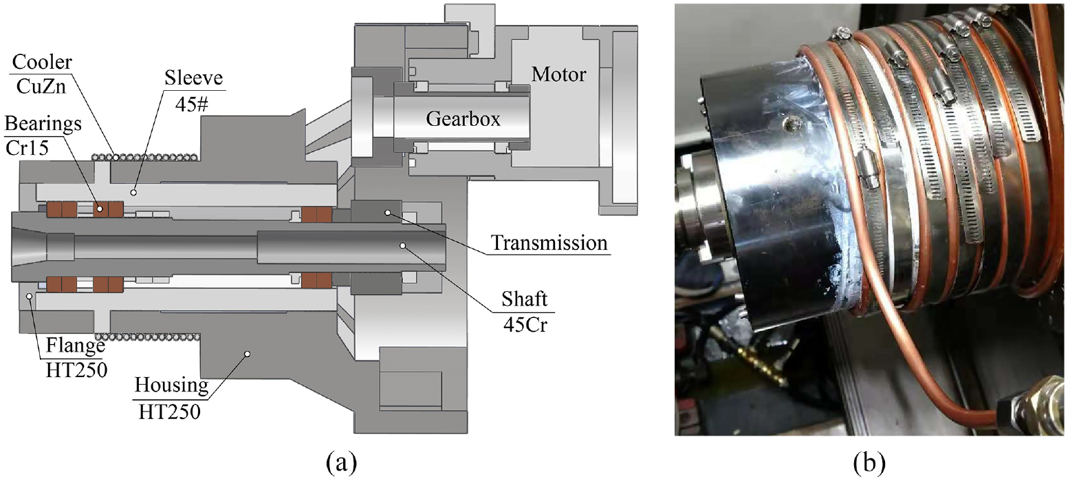
The spindle with an external cooler: (a) cross-section of the simplified geometrical spindle model and (b) install the helical tube cooler.
Boundary conditions for the spindle thermal simulation are detailed in Sections 2.1∼2.3, and the results of the thermal simulation are presented in Section 2.4.
Heat sources analysis of the ball-bearing considering lubrication
Quasi-static analysis of the angular contact ball-bearing
For the angular contact ball-bearing in operation, the forces on the rolling element(ball) are shown in Figure 2. Each ball (the jth ball) is under the contact normal loads (Qij and Qoj) of the inner and outer race and subjected to the centrifugal force Fcj and the gyroscopic moment Mgj, the contact angles change to αij and αoj from initial contact angle α0 under the forces. Elliptical Hertz contact area with major axis aij and minor axis bij is generated due to the normal loads. The ball-raceway contact angle αij and αoj, normal pressure Qij and Qoj, and contact area size (aij and bij) are calculated using the quasi-static mechanics. 12
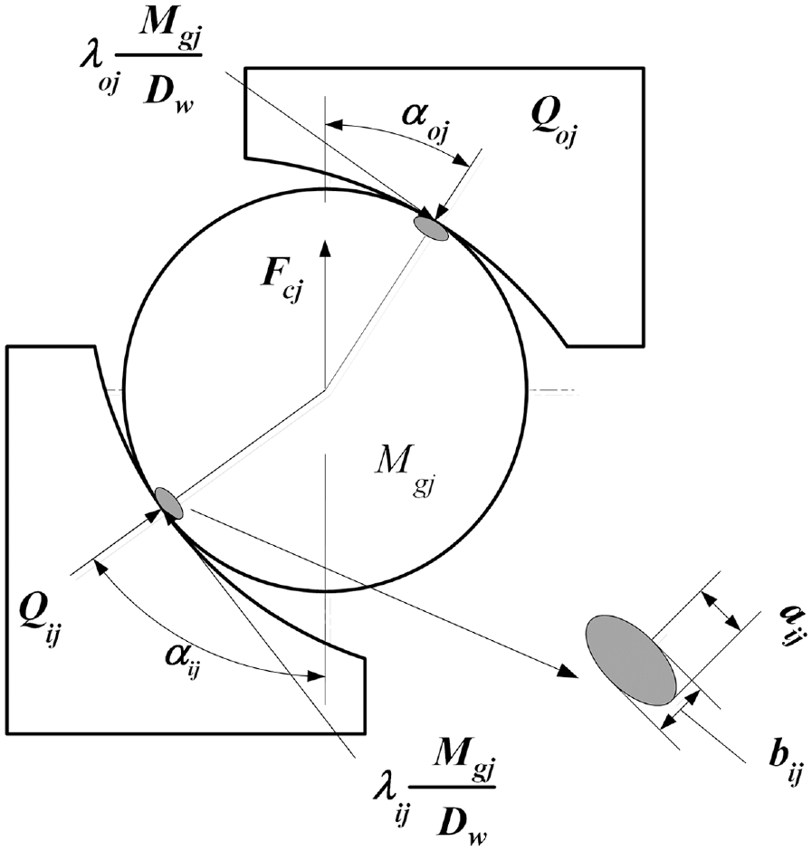
Forces diagram of the rolling element.
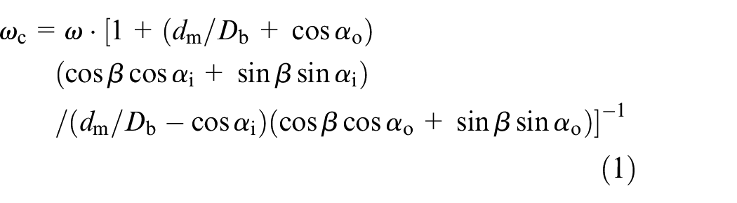
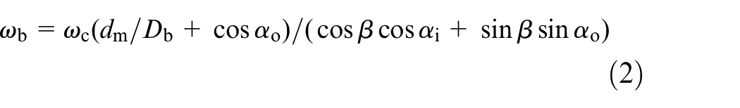
Then, the revolution angular velocity ωc around the bearing axis, the rotation angular velocity ωb, the spin angular velocity (ωsi and ωso) of the ball on the inner and outer races, and the included angle β of the ball rotation axis projections in radial and vertical planes (Figure 3), can be calculated as


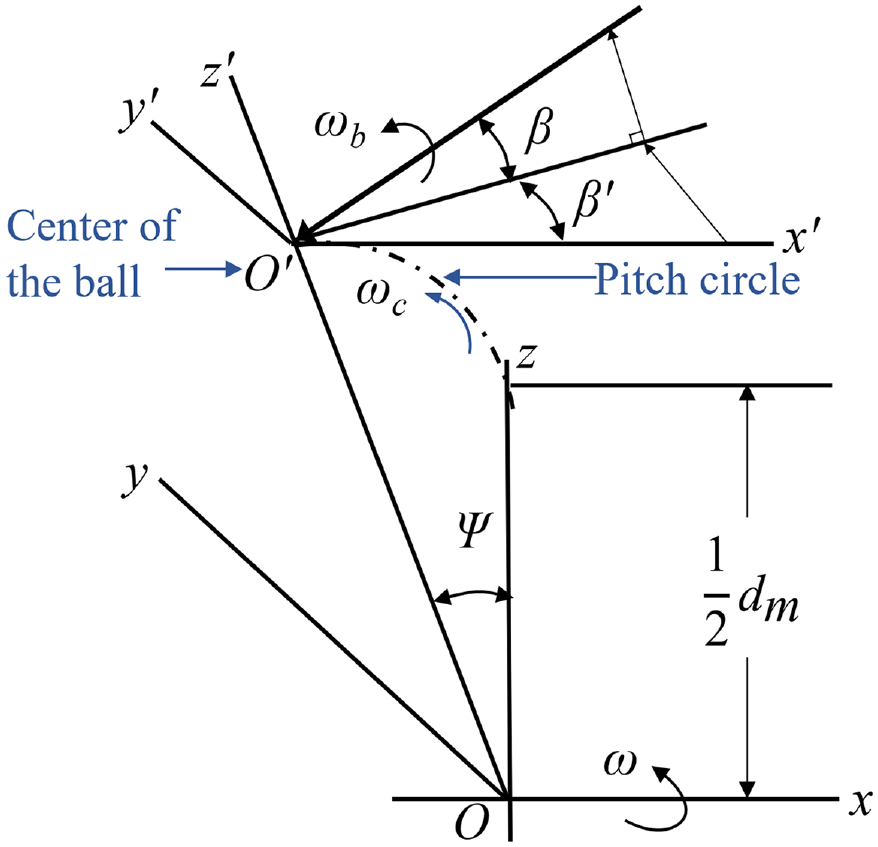
Ball rotation around the axis.
where Db is the ball diameter, dm is the pitch diameter, ω is the angular rotation velocity of the spindle.
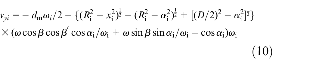
The differential sliding velocity vyo of the rolling element on the outer race is expressed as
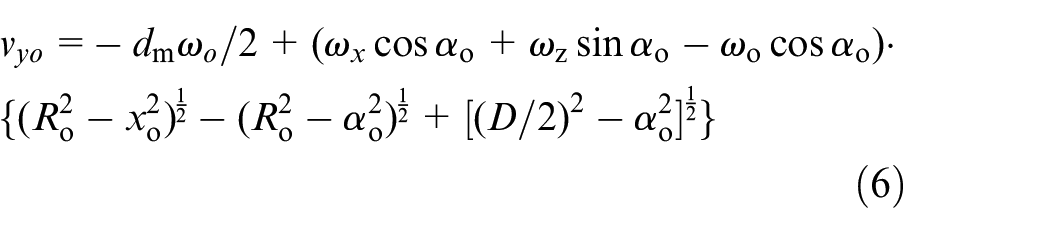
where


where ωx, ωy, and ωz are the angular velocity components in different directions, and ω is the rotation speed of the spindle. Moreover, the ball differential sliding velocity vyi of the inner race is similar to that of the vyo
Heat generation caused by the sliding friction
The sliding friction is a significant heat generation source of the angular contact ball bearing. Considering the lubrication condition and contact pressure between the ball and raceway, the contact is regarded as elastohydrodynamic and partial film lubrication, so the minimum film thickness hmin 13 is

where
The parameter
τy is the friction shear stress in the rolling direction of the ball-raceway Hertz contact area, and is expressed as follows:
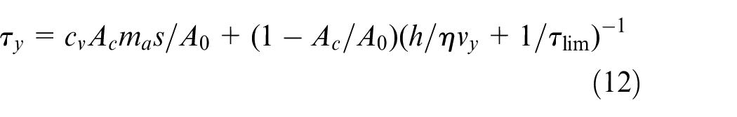
where cv is 1 or -1 depending on the sliding direction (forward or reverse), A0 is the Hertz contact area, Ac is the asperities contact area. τlim is the assumed value maximum shear stress under unlubrication friction, τlim = μm·p/(π·a·b), where a and b are the axes of the Hertz contact ellipse area, p is the normal pressure and μm is the empirically estimated maximum friction coefficient. h/ηvy is the Newtonian part dependent on the oil-film thickness h, viscosity η and sliding velocity vy.
h is the isothermal oil film thickness in the contact area, which can be expressed using Hamrock and Dowson’s point contact film thickness formula15,16:

Moreover, when the normal pressure is constant, the working temperature in the contact areas will increase with the accumulation of heat inside the bearing, and the kinematic viscosity of lubrication oil will decrease with the increase of the working temperature

where c is empirically set to 0.0233, T0 is the initial temperature which equals 20°C, T means the working temperature of the bearing. η0 is the lubricant viscosity at 20°C, and η is the lubricant viscosity at the operating temperature.
The theoretical model of the sliding friction shear stress is verified by the experimental results of Bair and Kottke 17 ; the results are shown in Figure 4.
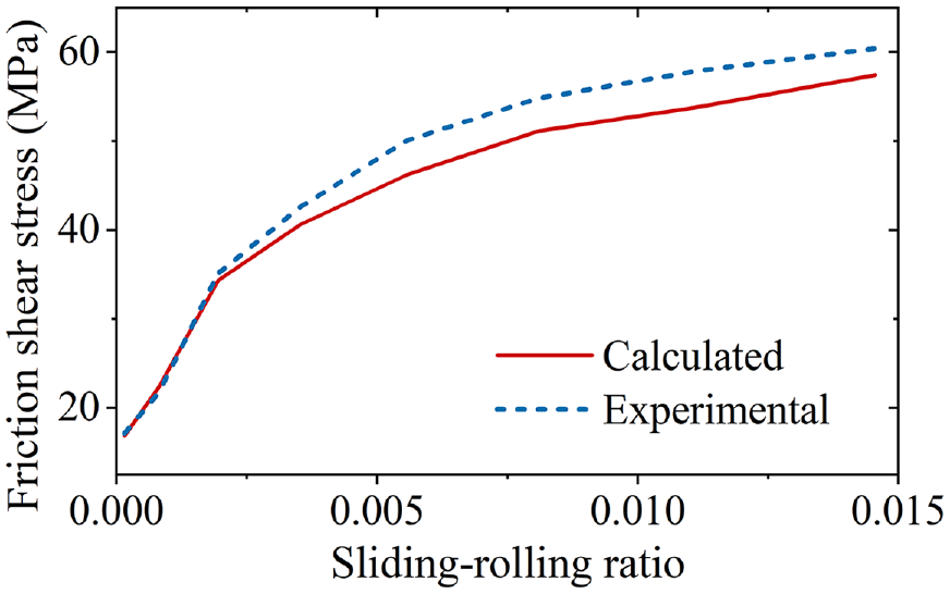
Comparison of the calculated and experimental traction force.
In the ball-raceway contact, along the rolling direction (y), the sliding friction heat generation rate can be calculated as
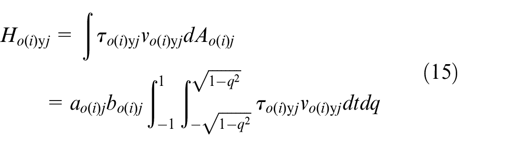
where o(i) is the outer race or the inner race that contacts the rolling element.
Heat generation caused by spinning motion friction and lubricant friction
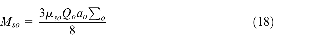
Spinning motion friction also causes significant heat generation; the spin friction torque Ms is expressed as18,19
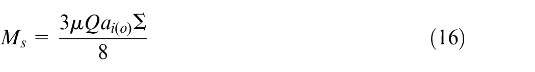
where μ is the friction coefficient and ∑ is the second ellipse integral of the Hertz contact area. Spin friction torques for the rolling element-raceway contact areas are respectively expressed as
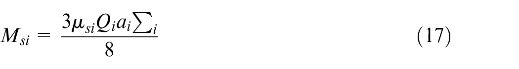
and the heat generation caused by spin friction is

where ωsi and ωso are given by equations (3) and (4).
Lubricant friction is another heat source, lubricant friction caused heat generation Hv is11,18,19

where
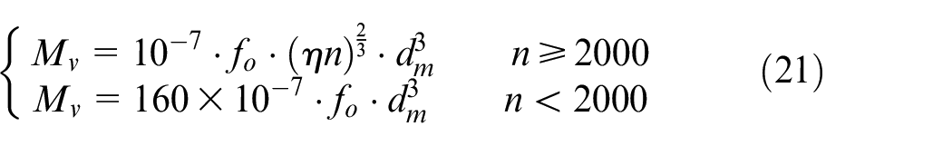
where dm is the pitch diameter, η is the kinematic viscosity of the lubricant (cSt), n is the operating rotational speed in revolutions per minute (rpm), fo is empirically chosen considering the bearing and lubricant type.
Total heat generation of the angular contact ball-bearing
Total heat generation of the bearing can be expressed as:

Taking the 7008C ball bearing as the study object, the established theoretical heat sources model is compared with the conventional integral model and the traction experiments-based heat sources model. 11 The theoretically calculated sliding friction heat generation generally meets the experiment-based sliding friction heat generation calculation, as is shown in Figure 4. The total heat generation calculated by the theoretical heat sources model is close to that of the experiment-based heat sources model. The calculations of the integral model seriously deviate from that of the two heat sources models (Figure 5).
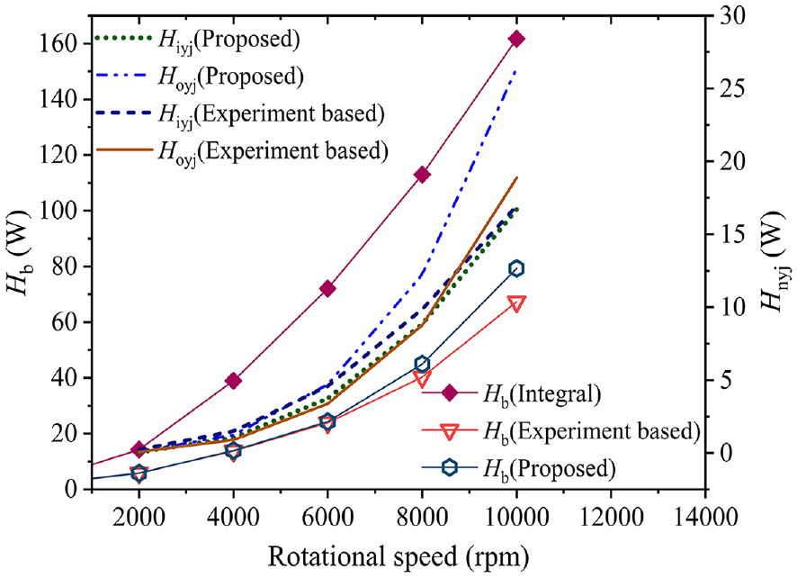
Heat generation calculation results for the 7008C ball bearing.
Transient thermal simulation results of the spindle under cooling
Other thermal boundary conditions for the thermal simulation of the spindle
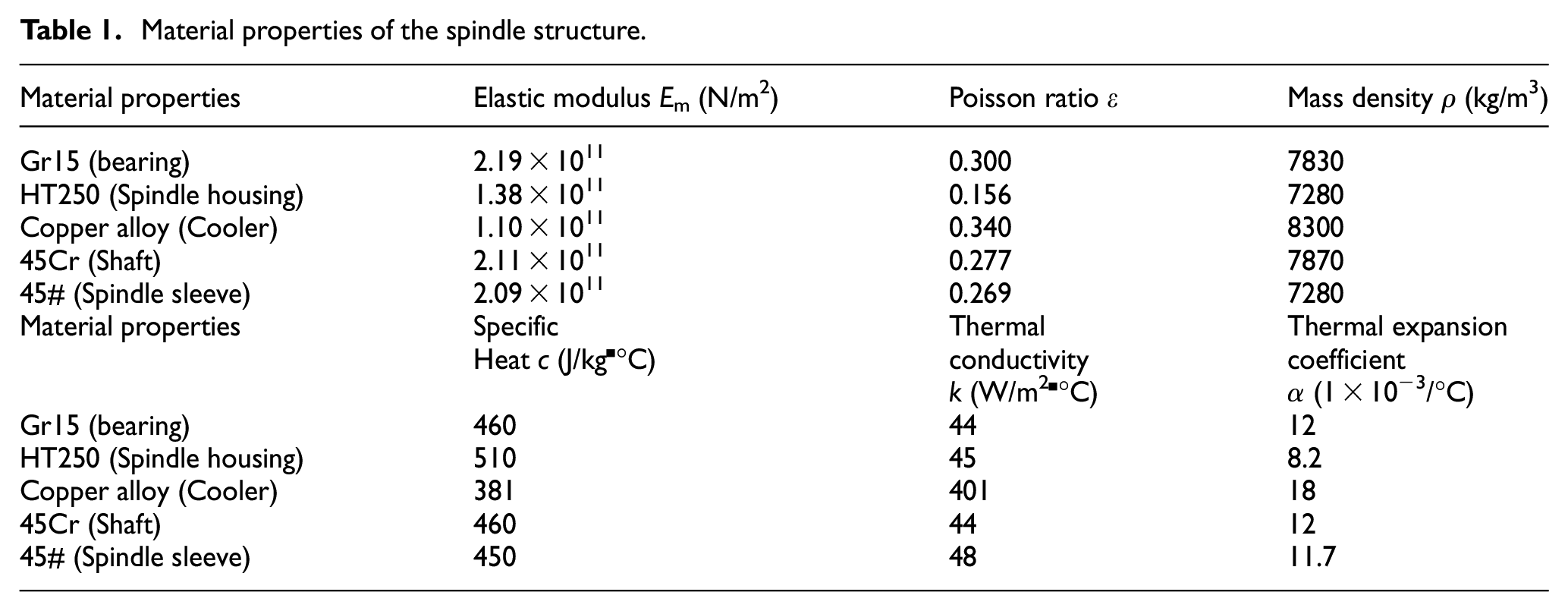
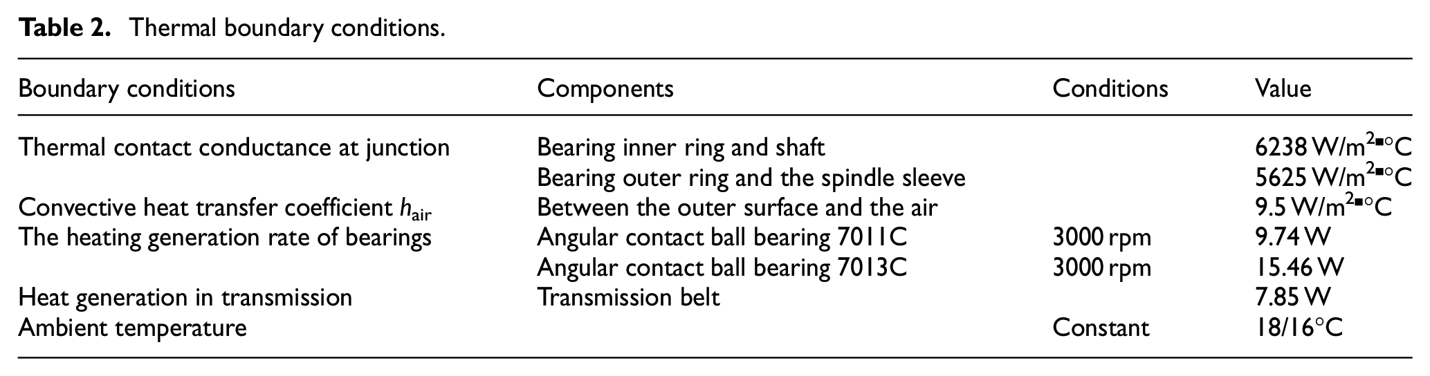
The thermal resistance of the grease coated cooler-housing interface, the contact thermal resistance model for solid-solid interfaces (such as the bearing outer ring and the bearing seat contact), the ambient air-housing heat convection, and the heat generation of the motor and transmission refer to our previous works20,21 and the literatures.10,22 The material properties of the spindle structure are detailed in Table 1, and the thermal boundary condition calculations is detailed in Table 2.
Material properties of the spindle structure.
Thermal boundary conditions.
Simulation of the thermal error suppressing effect for the mechanical spindle under external cooling
The thermal behavior of the mechanical spindle with an external cooler is simulated. The transient simulation process is set to 18 sub-steps, and each sub-step is set to 1200 seconds. The thermal simulation is conducted in ANSYS software. 23
As is shown in Figure 6(a) and (b), the thermal displacement of the bearing and shaft is more minor than 20.9 μm, thus proving that the external cooling scheme can effectively suppress the thermal error. The simulation results (Figure 7(a)) show that the spindle thermal error under cooling can quickly reach a stable state and possesses significantly superior stability than that without cooling. In the spindle thermal simulation results of vary-temperature cooling (Figure 7(b)), the thermal error variation trends change with the coolant temperature. The simulation results show that the external cooling scheme can effectively suppress the thermal error and influence the variation trends, and it is practicable to dynamically control the spindle thermal error by the external cooling with varying-coolant temperature.
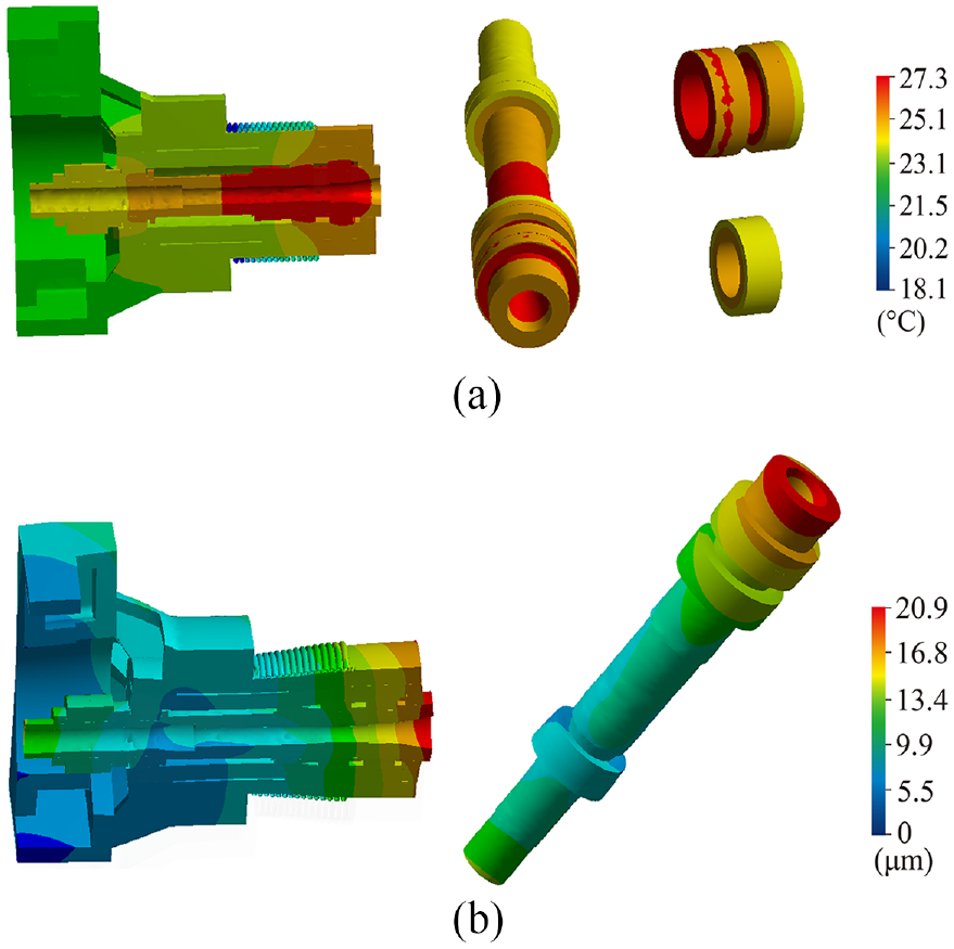
Temperature and deformation fields of the mechanical spindle under cooling: (a) temperature field (at 300 min) and (b) thermal deformation field (at 300 min).
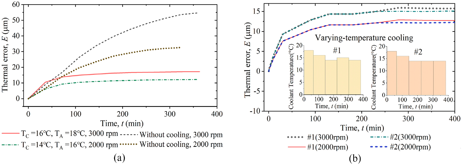
Simulated thermal error of the mechanical spindle under cooling: (a) E curves with constant temperature cooling and (b) E curves with temperature-varying cooling.
Determine the RITE on the basis of simulation results
In the active cooling process of the precision mechanical spindle, the preheating with constant coolant temperature (TC) is first conducted, and the thermal error feedback control is then performed when a thermal error (estimated by the regression model) reaches RITE.
In the preheating stage of constant TC, the ambient temperature (TA) and the initial temperature of the spindle structure are 18°C (autumn) and 16°C (winter). Less energy will be consumed in heat convection with ambient air if TC keeps close to TA because instruction for TC (uk) distant from TA leads to energy consumption in the coolant temperature controller. Thus, TC should be close to TA in the feedback control process to reduce energy consumption. Based on simulation results (Section 2), the constant coolant temperature in preheating is 16°C in autumn situations (TA = 18°C) and is 14°C in winter situations (TA = 16°C).
Adjusting and maintaining coolant temperature consumes significant energy in the active cooling of the spindle. The value of RITE mainly affects the total cooling energy consumption of the thermal error control process and only slightly affects the Stability of Thermal Error (STE) and thermal equilibrium time. Maintaining STE at a relatively high thermal error value can reduce the amount of heat that needs to be dissipated by coolant circulations, thus decreasing the energy consumption of TC adjusting in the coolant temperature controller. Referring to the thermal simulation results (Figure 7), for the feedback thermal error control with the rotation speed of 3000 rpm, RITE is set to 17 μm with TA of 18°C and TC varies around 16°C; as for the thermal error control with the rotation speed of 2000 rpm, RITE is determined to be 12 μm with TA of 16°C and TC varies around 14°C, and 9 μm with TA of 18°C and TC varies around 14°C.
The thermal error feedback control system for the spindle
The thermal error feedback control strategy
The thermal error feedback control strategy regards the “active cooling-mechanical spindle” system as a feedback control system so that the spindle thermal error can be stabilized for a long time owing to the homeostasis of the feedback control system. The feedback control system takes the spindle as the controlled object, the coolant temperature as the control variable, the thermal error as the controlled variable, the cooler as the actuator, and the heat generation and ambient temperature variation as a disturbance. The real-time measurement for spindle end-elongation is unable to conduct during conventional machining processes; thus, a regression model of the temperature-thermal error relationship is established and is used to provide feedback in the thermal error control.
The spindle thermal error feedback control adopts the proportional-integral-derivative (PID) algorithm. The PID controller is given as follows,
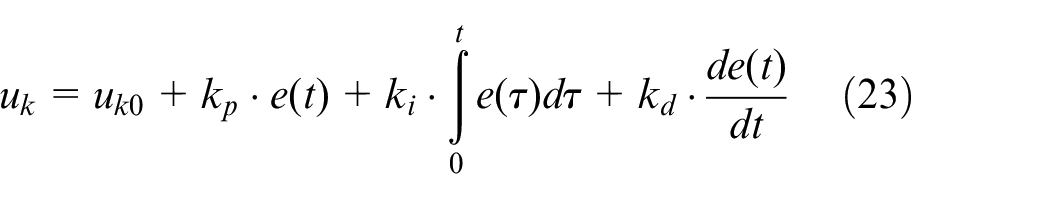
where uk is the instruction for TC, uk0 is the controller bias and the initial uk when the control starts, and e1(t) is the control error that equals RITE minus the estimated E. The controller parameters are the proportional gain kp, integral gain ki, and derivative gain kd. Moreover, a thermal error model, which uses real-time temperature measurement as input, will be employed to output thermal error estimation for feedback.
The feedback control scheme for the spindle thermal error is shown in Figure 8. The thermal error feedback control system consists of the spindle’s active cooling module, the spindle structure’s real-time monitoring module, and the coolant recirculation.
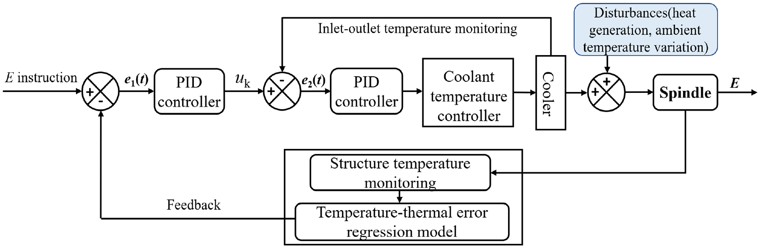
The thermal error feedback control scheme.
Software and hardware of the thermal error feedback control system
After the thermal error suppressing effect is pre-validated by simulation (Section 2), the thermal error feedback control system is developed, including the computation module to run the algorithms, the real-time monitoring module, the cooling module, and the PLC and PC based data exchange approach to integrating the modules.
Framework of the thermal error control system integrated with the modules
Figure 9 shows the framework of the thermal error feedback control system, integrating the industrial computer-based computation module, the real-time monitoring module, and the cooling module. SQL Server runs on the computer, and a Siemens S7-200 PLC is used to realize the data exchanging among the modules.
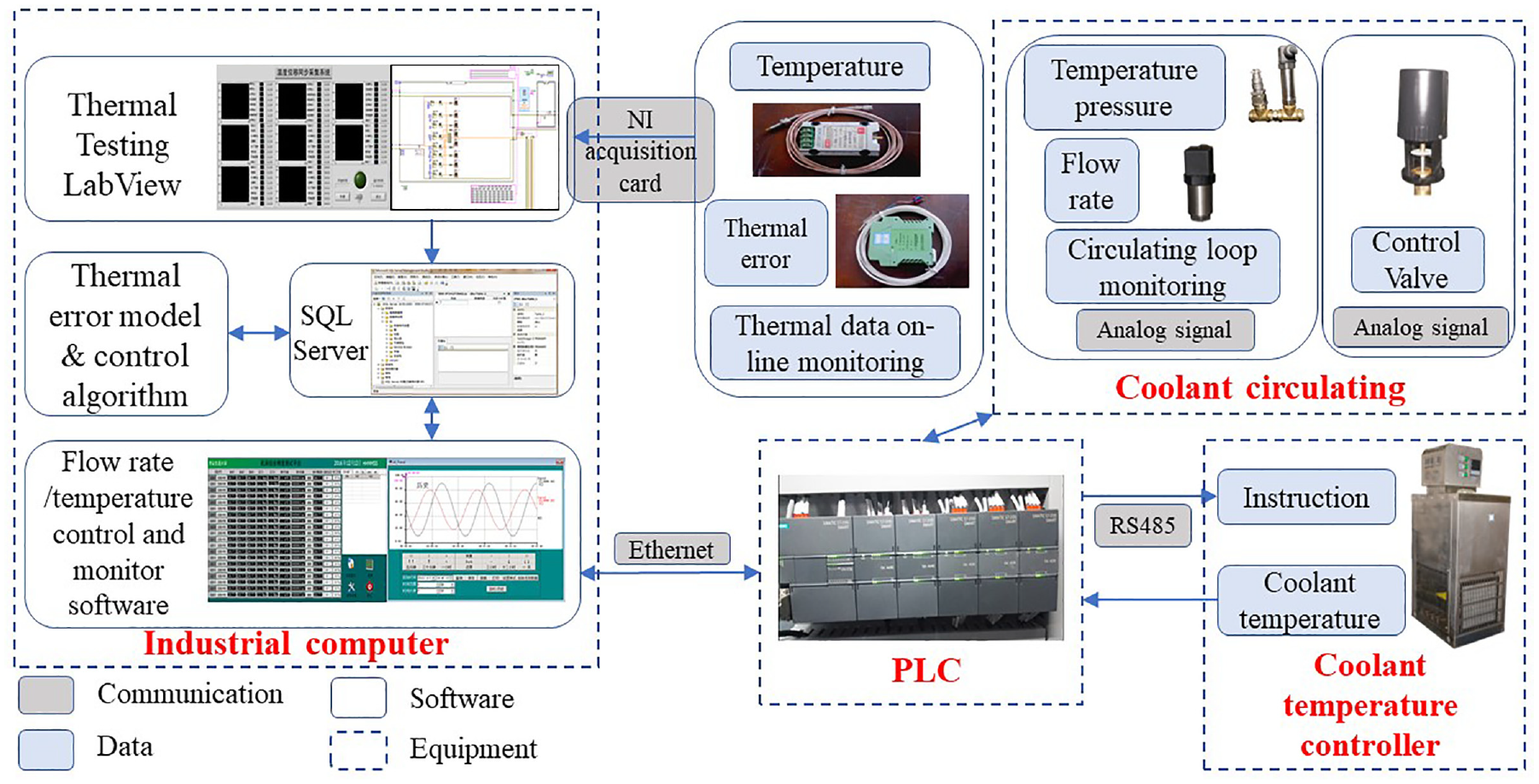
Data exchange and software communications.
The configuration software (Force Control), which runs on a host industrial computer, is adopted to control and monitor the coolant recirculation loop. The coolant temperature is adjusted according to the control instruction and is then pressurized with a recycle pump and stabilized with a turbine flowmeter and flow control valve during the circulation. The coolant flows in the helical cooler and then recirculates to the coolant temperature controller. The data acquisition software for the coolant recirculation (coolant flow velocity, pressure, temperature of the cooler inlet and outlet, structural temperature) is developed using secondary development of Force Control configuration software and the data exchange between the active cooling module and the host computer through the SQL Server database. Same for the data exchange between the acquisition software in a host computer and the synchronous measurement system. The control module uses SQL query operation to write the latest acquired data in a database table and execute the feedback control algorithm. The coolant temperature (uk) instructions are reported to another table in the database. Data in the table is then transferred to a real-time database using an ODBC router. Finally, the uk is sent to the PLC of the coolant temperature controller by an I/O driver.
Real-time monitoring module for the spindle structure
The thermal behavior of the mechanical spindle of a precision boring machine is investigated experimentally based on our previous works. Synchronous temperature and displacement data are gathered by online measurement with an acquisition card (NI SCXI-1600 series). The sampling interval is 1 s, the precision of the temperature sensor is ≤ ±0.1°C, and the non-linearity in the displacement sensor is ≤±1%.
The experiments are conducted in a workshop with a constant ambient temperature of 18 and 16°C (autumn and winter). Photographs of the experiment site and the sensors setup is shown in Figure 10. The eddy current displacement sensor directly faced the end of the spindle detection rod, so the thermal error of the spindle can be measured. Regarding the PT100 temperature sensors, T2 is embedded beneath the housing and direct contact with the outer ring of the bearing, T4 is installed on the front flange, T1, T3, T5, and T6 are installed on the rear of the housing, so the disturbances from the cooler will be alleviated.
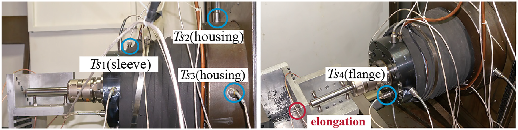
Thermal sensors arrangement.
Before the machining is started, a precision boring machine usually preheat until the equilibrium state is reached. The thermal equilibrium means the stable state of its temperature field and thermal deformation field, and the stability of the thermal error can be used to judge whether the equilibrium state is reached.
Moreover, the pressure and the temperature sensors are setup the inlet and outlet of the cooler to monitor the flow rate and temperature of the recirculating coolant.
The cooling module for the mechanical spindle
The cooling module refers to our previous study 14 and is illustrated in Figure 11. A liquid temperature controller and a pressure pump are employed to adjust the temperature and flow velocity of the coolant. The coolant is pressurized with the pump and regulated by a turbine flowmeter and flow valve in the recirculation loop. The coolant flows in the cooler and recirculates to the liquid temperature (TC) controller (Figure 11(a)). The helical cooler is externally installed on the spindle, and thermal grease fills the cooler-housing interface to promote heat transfer (Figure 11(b)). The coolant temperature and flow velocity are adjusted according to the control instruction transmitted by the PLC (Figure 11(c)).
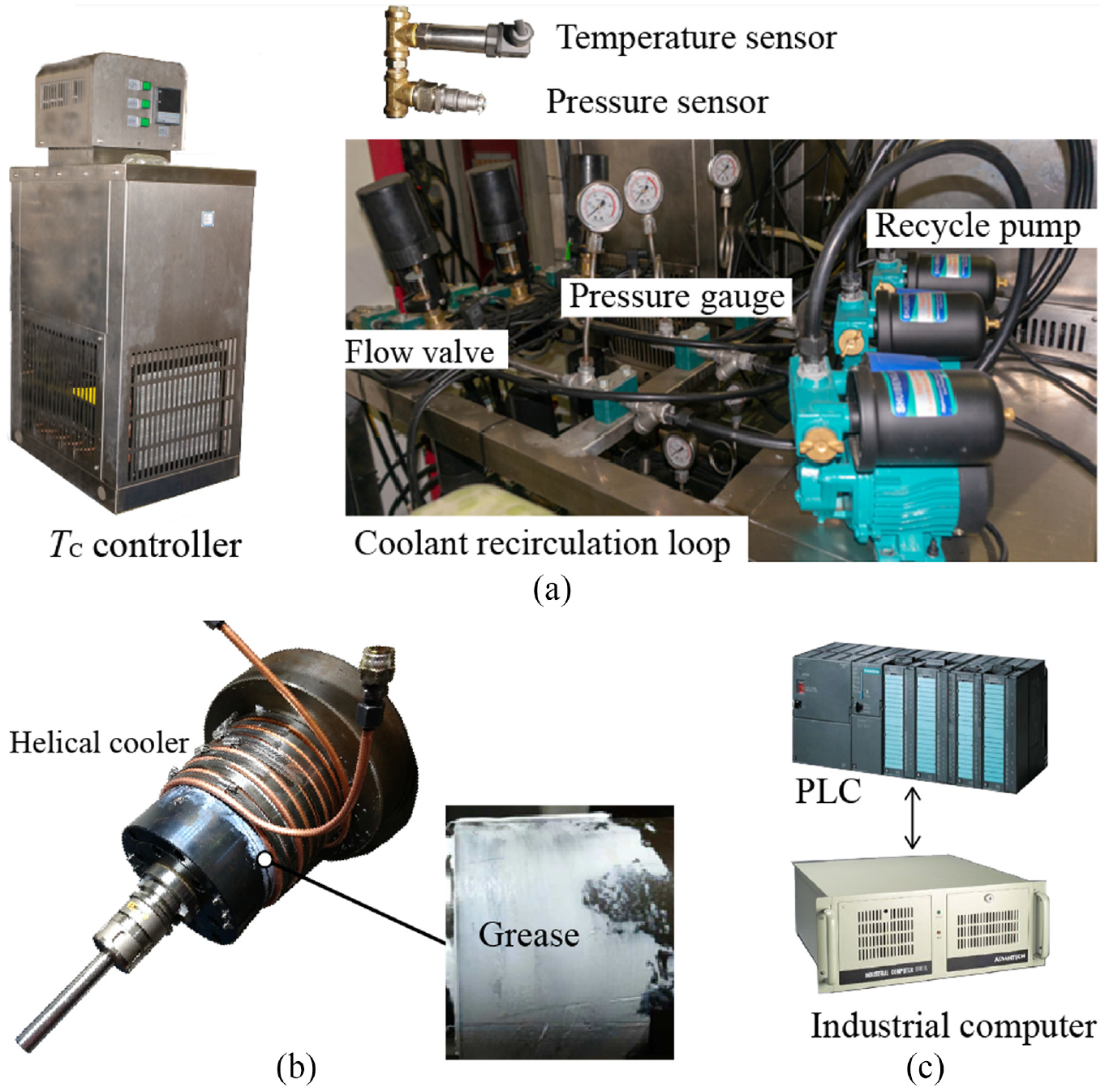
Cooling system for the spindle: (a) liquid temperature controller and recirculation, (b) helical cooler on the mechanical spindle, and (c) industrial computer and PLC.
The thermal error model to provide feedback
Then, the Support Vector Regression (SVR) is adopted to establish the regression model of the temperature-thermal error relationship.24,25 Three experimental datasets from different work and cooling conditions are adopted for training the spindle thermal error model (Figure 12). The experimental data can well reflect the effect that the coolant of varying temperature act on the spindle. The selected positions for temperature measuring are relatively distant from the cooler and close to the significant heat sources (Section 3.2.2). Thus, temperature measurements are less affected by the variations in TC and are strongly associated with the thermal elongation in the spindle (Figure 10).
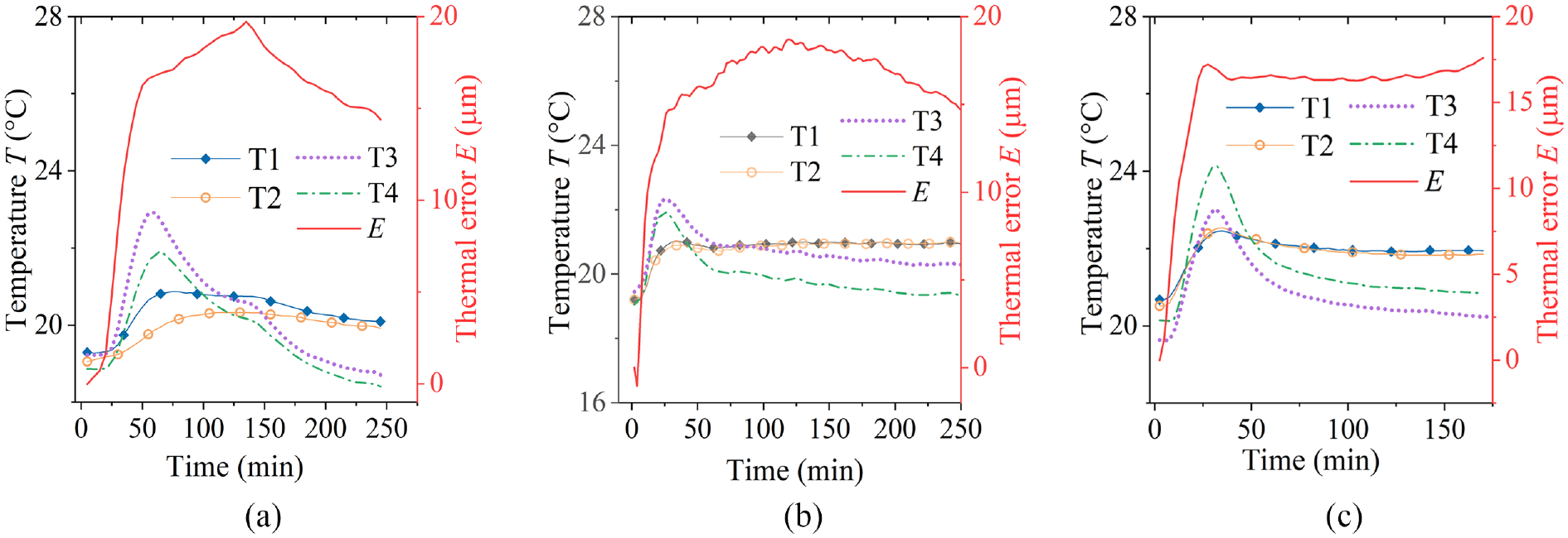
Experimental datasets for training the thermal error model.
The SVR algorithm is employed to establish the thermal error model with the experimental datasets, where the temperature is input, and the thermal error is output. Fitting results for the thermal error are shown in Figure 13.
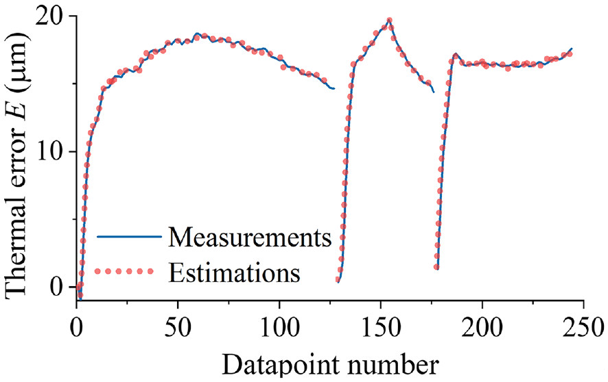
Fitting the thermal error modeling dataset.
Application and experimental verification of the thermal error feedback control strategy
Quantitative evaluation method of STE
To quantitatively evaluate the STE using discrete derivatives, the fluctuations in the measured thermal error curves should be avoided. The significant variation trend of the thermal error will be reflected. The spindle thermal error, which varies non-linearly with time, is fitted to a smooth curve by the least-square algorithm:

STE is the discrete derivative of fitted thermal error f(t) to time t.

The spindle thermal deformation-induced machining error is minimal when the absolute STE value is close to 0. The thermal error is considered stable when STE becomes less than a threshold value, then the stable part of the spindle thermal error can be eliminated by setting the tool. The thermal error can be considered stable when the absolute value of STE becomes less than 0.5 × 10⁻³ μm/s, namely the stable state.
Performance of the spindle thermal error feedback control strategy
In the active cooling experiments of the precision mechanical spindle, the spindle is preheated by constant TC until the thermal error reaches a threshold (close to RITE), then the thermal error feedback control is triggered to run; that is to say, when the E estimation reaches RITE, the active cooling strategy switches to feedback control from constant TC preheating process. The PID parameters are empirically and experimentally set to kp = 2, ki = 0, kd = 50 in the experiments.
Experiments of different work and ambient conditions are conducted to validate the thermal error feedback control strategy. The work conditions are detailed as follows. Work condition #1: the spindle operates at a constant rotation speed of 3000 rpm. Work condition #2: the spindle operates at a constant rotation speed of 2000 rpm. Work condition #3: the spindle operates at 3000 rpm before 100 min, 4000 rpm between 100 and 250 min, and 2000 rpm until the experiment ends. Work condition #4: the spindle operates at 2000 rpm before 100 min, 3000 rpm between 100 and 220 min, and 2500 rpm until the experiment ends. Then, the thermal error measurements are fitted by using equation (24), so the fitted curves are smooth, and the STE of each experiment can be obtained.
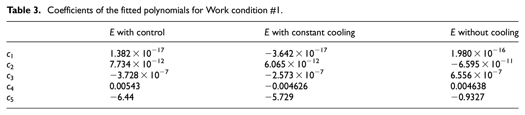
The first experiment is conducted under condition #1 of constant rotation speed with a TA of 18°C (Figure 14(a)). The fitted polynomial is given in Table 3, and the STE curves with or without control are shown in Figure 14(b). The absolute value of STE with constant cooling (TC = 16°C) becomes less than 0.5 × 10⁻³μm/s at 252.2 min and is larger than 0.4087 × 10⁻³μm/s in the entire experiment process. In contrast, the absolute value of STE with control becomes less than 0.5 × 10⁻³μm/s at 97.2 min and is no larger than 0.2 × 10⁻³μm/s after 120.3 min. Moreover, the stable state of the Thermal Error Variation Rage (TEVR) under the feedback control strategy is 1.92 μm.
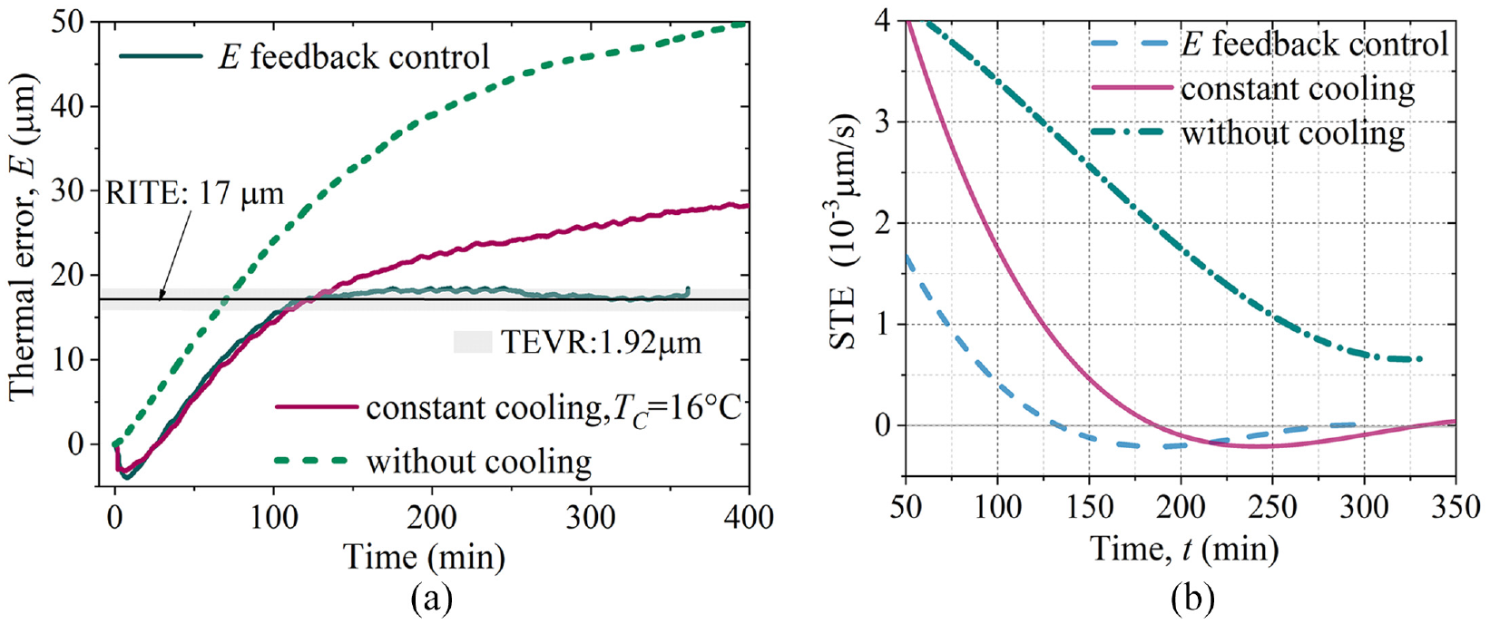
Thermal error variation for a spindle under Work condition #1 (TC = 16°C, TA = 18°C): (a) measured and fitted E curves and (b) STE.
Coefficients of the fitted polynomials for Work condition #1.
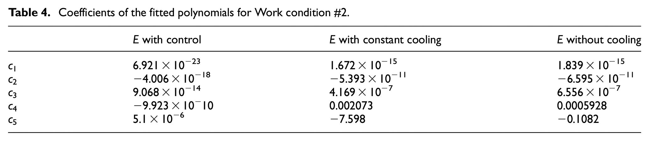
The second experiment is conducted under condition #2 of constant rotation speed with a TA of 18°C (Figure 15(a)). E curves without control rose steadily throughout the experiment; the E curve with feedback control stabilized at about 9 μm and was kept for around 180 min. The fitted polynomial is given in Table 4, and STE curves are shown in Figure 15(b). The absolute value of STE with constant cooling (TC = 14°C) becomes less than 0.5 × 10⁻³μm/s at 232.4 min and is always larger than 0.4566 × 10⁻³ μm/s in the experiment; the absolute value of STE with control is always less than 0.5 × 10⁻³ μm/s after 94.9 min and is no more than 0.2 × 10⁻³ μm/s after 114.9 min. For the thermal error under the feedback control strategy, TEVR is 1.52 μm.
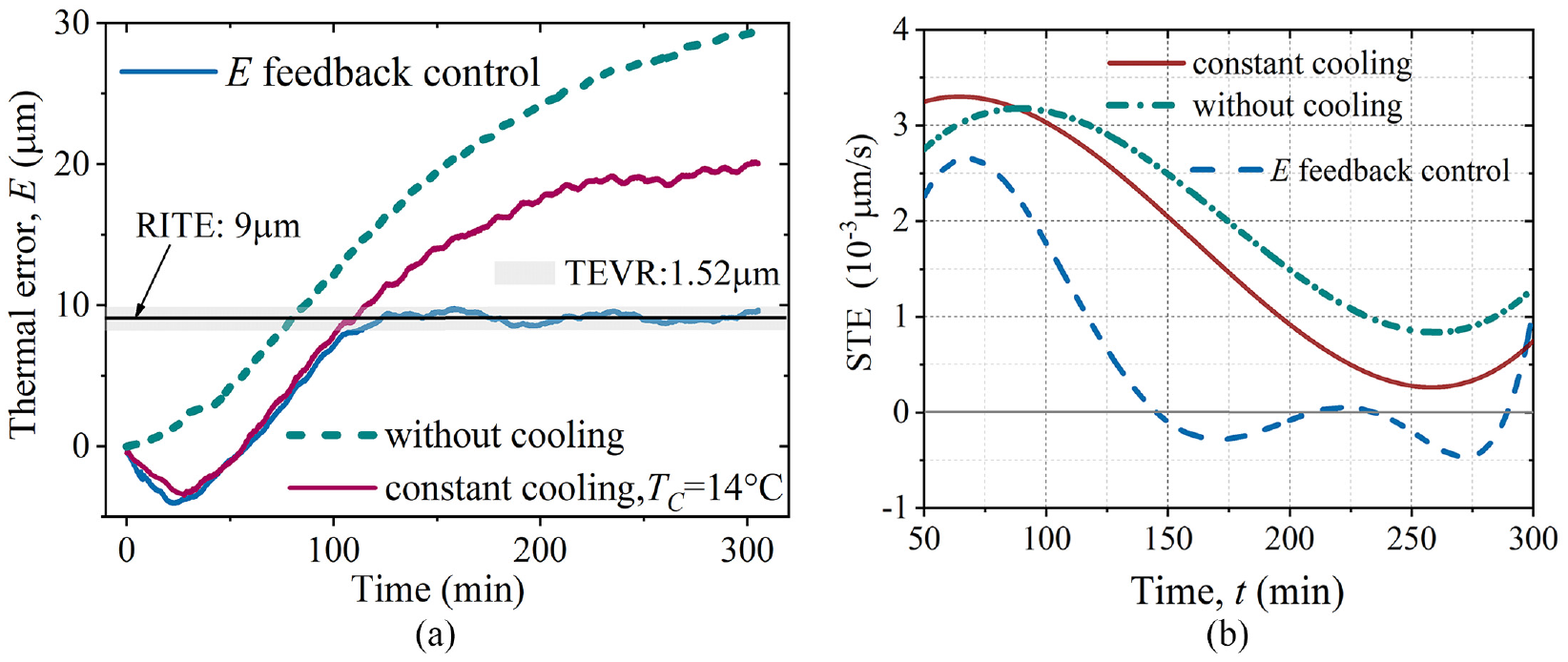
Thermal error variation for a spindle under Work condition #2 (TC = 14°C, TA = 18°C): (a) measured E curves and (b) STE.
Coefficients of the fitted polynomials for Work condition #2.
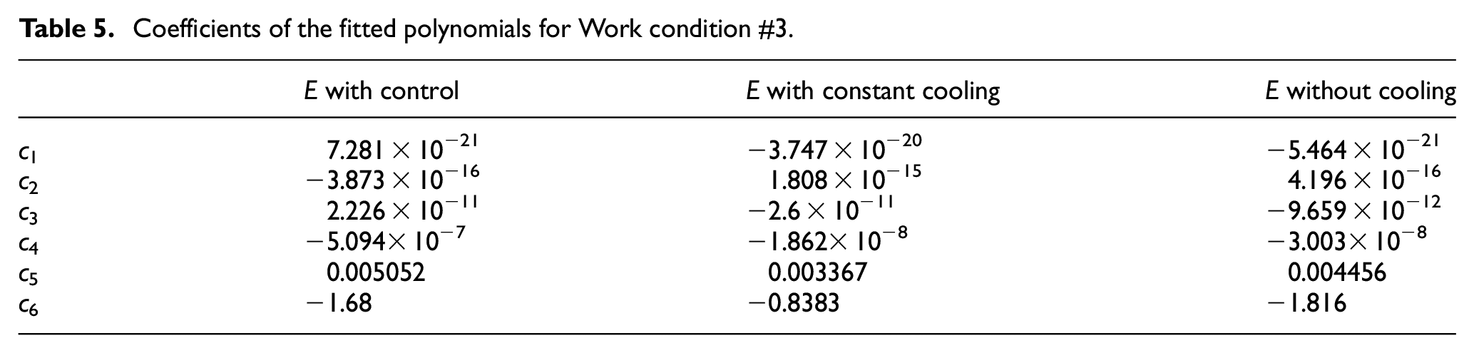
For the varying rotation speed of work condition #4 under TA of 18°C (Figure 16(a)). The fitted polynomial is given in Table 5, and the STE curves with or without control are shown in Figure 16(b). The absolute value of STE with constant cooling (TC = 16°C) becomes less than 0.5 × 10⁻³μm/s at 223.5 min and is larger than 0.4087 × 10⁻³ μm/s in the entire experiment process. In contrast, the absolute value of STE with control becomes less than 0.5 × 10⁻³ μm/s at 117.5 min and is smaller than 0.2 × 10⁻³ μm/s after 132.3 min. Moreover, under the feedback control strategy, the equilibrium stage’s TEVR is 1.91 μm.
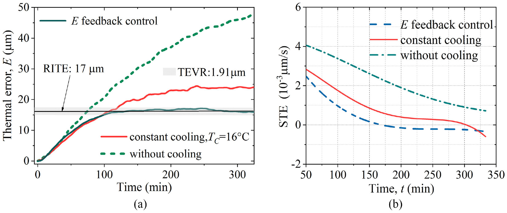
Thermal error variation for a spindle under Work condition #3 (TC = 16°C, TA = 18°C): (a) measured and fitted E curves and (b) STE.
Coefficients of the fitted polynomials for Work condition #3.
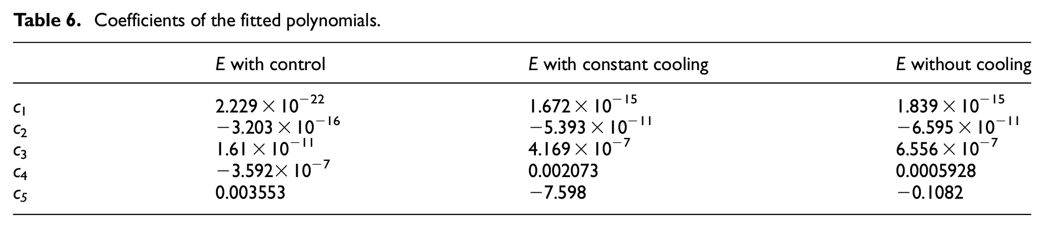
For the varying rotation speed condition under TA of 16°C (Figure 17(a)). The E curve with feedback control stabilized at about 12 μm and was kept for around 200 min. The fitted polynomial is given in Table 6, STE curves with or without control are shown in Figure 17(b). The absolute value of STE with control is always less than 0.5 × 10⁻³ μm/s after 97.4 min and is no more than 0.2 × 10⁻³ μm/s after 121.7 min. For the thermal error under the feedback control strategy, TEVR is 1.69 μm. The absolute value of STE with constant cooling (TC = 16°C) becomes less than 0.5 × 10⁻³μm/s at 204.4 min.
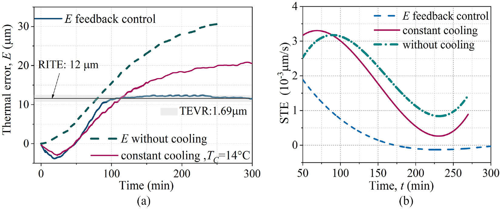
Thermal error variation for a spindle under work condition #4 (TC = 14°C, TA = 16°C): (a) measured and fitted E curves and (b) STE.
Coefficients of the fitted polynomials.
Discussion of the experimental results
As shown in Figures 14 to 17, the thermal error can hardly reach a stable state without cooling; the E curves with constant cooling kept rising throughout the experiment process, while the E curve with feedback control stabilized around the pre-set RITE. The time when the spindle thermal error with control reaches a stable state (STE < 0.5 × 10⁻³ μm/s), namely the thermal equilibrium time, is significantly more advanced than that with constant TC cooling by 61.46% 58.08%, 52.57%, and 47.58% in the four cases respectively.
The thermal error stability in the stable state is also primarily enhanced. In the experimental comparison under Work condition #1, TEVR of the spindle with proposed active cooling is 1.92 μm in the stable state, while the variation range of the spindle with constant cooling (TC = 16°C) is 4.10 μm in the stable state, the TEVR is reduced by 53.17% (Figure 14(a)). TEVR of the spindle with proposed active cooling is 1.52 μm in the stable state under Work condition #2, while the variation range of the spindle with constant cooling (TC = 14°C) is 3.39 μm in the stable state, so TEVR is reduced by 55.16% (Figure 15(a)) under Work condition #2. TEVR of the spindle with proposed active cooling is 1.91μm in the stable state under work condition #3, while the variation range of the spindle with constant cooling (TC = 16°C) is 3.25 μm in the stable state, so TEVR is reduced by 41.23% (Figure 16(a)) under work condition #3. Under work condition #4, TEVR of the spindle with proposed active cooling is 1.69 μm in the stable state, while the variation range of the spindle with constant cooling (TC = 16°C) is 3.39 μm in the stable state, so TEVR is reduced by 55.16% (Figure 17(a)). In conclusion, compared with constant cooling, the feedback control based active cooling.
Conclusion
In this study, a mechanical spindle is taken as a research object to present the theoretical heat sources model of the bearing, the spindle thermal simulation, and the thermal error feedback control-based active cooling strategy for stabilizing the rapidly-varying thermal error. The core conclusions are as follows.
Accurate bearing heat generation calculation is vital for the effective thermal simulation of the mechanical spindle. The sliding friction caused by heat generation is theoretically calculated based on the elastohydrodynamic and partial film lubrication theories, independent of traction experiments. Theoretical calculation results are close to the experimental results in comparison. On this basis, thermal simulation of the spindle can be conducted to pre-validate the thermal error suppressing and variation trend influencing effect and obtain the RITE for the feedback control.
Consider that the coolant temperature adjustment is slow, the thermal error feedback control is better performed after preheating when the thermal error variation is not too rapid. As in this study, the thermal error feedback control is only triggered when the real-time estimation of the thermal error reaches RITE.
Quantitative evaluation of STE and TEVR shows that the feedback thermal error control significantly advances the thermal equilibrium time and improves the long-term thermal error stability. Moreover, experimental results from different ambient temperatures and work conditions preliminarily validate the adaptability of the proposed strategy.
Footnotes
Declaration of conflicting interests
The author(s) declared no potential conflicts of interest with respect to the research, authorship, and/or publication of this article.
Funding
The author(s) disclosed receipt of the following financial support for the research, authorship, and/or publication of this article: This work is financially supported by the National Science Foundation of China (No. 52205540), the Natural Science Basic Research Program of Shaanxi (No. 2023-JC-QN-0505) the Natural Science Fundamental Research Program of Shaanxi Province (No. 2021JQ-475), the Science and Technology Major Project of Shaanxi Province (No. 2018ZDZX01-02-01), and the Shandong Tai Shan industrial leader talent project (No. 2017TSCYCX-24).