
Abstract
In the present study, the two configurations of the combined intercooled cascade supercritical carbon dioxide (sCO2) cycle/organic Rankine cycle (ORC) (configuration-1) and the combined intercooled cascade sCO2 cycle/parallel double evaporator ORC (PDORC) (configuration-2) were considered for the comparison on the basis of thermodynamic performance. Solar power tower (SPT) was considered as heat source for both the configurations. The effects of SPT design parameters on the systems were investigated. It was concluded that the addition of basic ORC and PDORC to the standalone intercooled cascade sCO2 cycle enhanced the thermal efficiency by 2.26% and 6.66% respectively, at 950 W/m2 of direct normal irradiation (DNI). In the case of basic ORC and PDORC, the waste heat recovery ratios were 0.1197 and 0.1775, respectively. It was also discovered that configuration-2 performed better than configuration-1 in terms of waste heat recovery and its optimized thermal efficiency was found as 52.34%. An exergoenvironmental analysis also performed on the present systems. Exergoenvironmental impact index decreases from 1.6504 to 0.6801 with increase in DNI while the exergetic stability factor increase from 0.3773 to 0.5952 with DNI.
Introduction
Demand of energy is increasing continuously due to rapid population growth and industrial development. 1 As a result, there is an ongoing growth in the usage of fossil fuels, which raises carbon emissions. Stocks of fossil fuels are, however, steadily declining. Finding trustworthy and clean energy sources becomes difficult as a result. 2 Biomasses, wind, geothermal and solar are some renewable energy sources which are being used to produce the ecofriendly power. Among these various renewable energy sources solar energy can produce economic and noise free operations. However, solar installation cost is high (collectors and receiver purchasing cost) and it gave power in all weather but its storage unit cost is also fairly high. 3
The solar power tower (SPT) is the newest CSP (concentrated solar power) technology. The SPT technology consists several sub systems such as thermal storage (optional), receiver, 75–150 m high tower, heliostats having 50–150 m2 per heliostat area and this integrated a energy conversion system. Solar radiation incident upon the heliostats via this concentrated on the receiver where it heated the heat transfer fluid which is further used to produce power through high temperature power cycle and/or process heat for industry. 4 Several research on SPT-driven cycles were conducted, such as combined recompression sCO2 cycle and transcritical CO2 cycle,5,6 supercritical CO2 Brayton cycle, 7 with or without main compressor intercooled recompression sCO2 cycle, 8 and multi-generation combine cycle. 9
Supercritical CO2 is nothing but CO2 above 7.38 MPa pressure and 30.9°C temperature. Furthermore, the sCO2 cycle is the thermodynamic cycle in which sCO2 used as working fluid. The density of the CO2 at the inlet of the compressor is 60% of the density of water; therefore compression work is reduced as compared to the other fluids. Also at vicinity of the critical condition it becomes incompressible. Therefore the sCO2 cycle is compact. 10 The sCO2 receive the heat from the various heat sources such as solar, geothermal, nuclear, coal energy and natural gas. 10 Khan and Mishra 11 published a research on the partial heating sCO2 cycle combined with the ORC. This cycle received heat from the parabolic trough solar collector (PTSC). They also looked into the effect of the solar system on the overall functioning of the combined cycle. They concluded that thermal efficiency boosted by 4.47% by incorporating ORC into the base cycle. Finally, they discovered that R1233zd(E) performed better than other working fluids studied, including R1234ze(Z), R1234yf, R1234ze(E), R1243zf, R1224 yd(Z). Khan and Mishra 12 also evaluated a pre-compression sCO2 cycle to an ORC incorporated with the SPT. The ORC improved power output and thermal efficiency of base pre-compression cycle by 4.52% and 4.51%, respectively. They also determined that R227ea absorbed the more heat of the working fluids studied. In another study, thermal and the economic assessment of the sCO2 pre-compression driven by the SPT has been performed by Khan and Mishra 13 in which ORC worked as waste heat recovery cycle. They found that at 950 W/m2 of DNI, maximum thermal performance has been gotten by R1336mzz(Z) fluid. In another study, Khan and Mishra 14 used low climate change potential fluids to conduct a thermal evaluation of an SPT-driven main compressor intercooled recompression sCO2 cycle. They discovered that adding the ORC enhanced the thermal efficiency of the complete cycle by 7%–8% when compared to base cycle. Kim et al. 15 also performed a comparison study on 12 different sCO2 cycle configurations, of sCO2 cycles as land filling gas turbine. They discovered that the recompression and pre-compression cycle were more thermally efficient than the other investigated cycles. They also proposed future studies on the merging of two cycles. Yu et al. 16 investigated four configurations of CO2 cycle such that recompression cycle, flow split recompression cycle, pre-compression and simple recuperated cycle to recover the waste heat from internal combustion engine. In addition, the waste heat recovery ratio and thermal efficiency of the four systems were calculated. The maximal waste heat recovery factor was determined at the 5.8 MPa for pre-compression and 7.65 MPa for simple sCO2 cycle. Furthermore, the split flow cycle was discovered to be the best and most consistent cycle. Neises and Turchi 17 carried out the performance, design and cost analysis of the three molten salt solar power tower-driven sCO2 cycle configurations such as partial cooling, simple cycle, recompression cycle. As a result, the recompression cycle was obtained maximum thermal efficiency compared to the other two cycles. While on the basis of cost, partial cooling cycle was found more expensive cycle than other two cycles due to high turbo-machinery.
One extra compressor and one intercooler are used in the intercooled cascade cycle 18 than in the other cascade cycle (single heated). The intercooling process increased the turbine work while it reduces the compressor work, resulting in high thermal cycle efficiency compared to the basic cascade cycle for the same baseline conditions. 18 As a result, due to the greater impact of increased thermal efficiency of the cycle than the lack of heat absorbed, this cycle has 0.09 MW higher net produced work. This cycle, on the other hand, generates equivalent net work along with the more components than partial heated cycle. 15
Aside from that, ORC is a valuable technology for recovering waste heat at the low temperature. In the current case, ORC has been used as a bottoming cycle. In present study two deferent configurations of ORCs have been in cooperated as waste heat recovery cycle. A few studies back up this assertion. For example, Shaaban 19 conducted a solar operated combined study steam Rankine cycle in which ORC has been taken as the waste heat recovery cycle. Author also examined the 15 working fluids in the ORC. It was observed among the selected fluids R1234ze(Z) was recommended as best fluids on the basis environmental, thermodynamic, economic and safety concern. Hoang 20 studied the performance of the ORC which was used as the bottoming for using diesel engine exhaust heat. The ORC thermal efficiency was found as 25%. While with combined cycle with diesel engine it can be found 90%. Song et al. 21 also performed a study in which ORC is applied as heat recovery cycle. They observed that ORC is responsible to enhance thermal efficiency of the base sCO2 cycle. Also ORC was able to use the waste heat completely. Apart from basic ORC, PDORC is also suitable to recover more residual heat in the comparison of the basic ORC. More work can be obtained by PDORC due to use of two turbines. 22
It was concluded from the literature review that by using ORC as waste heat recovery cycle, performance of the intercooled cascade sCO2 cycle could be further improved. However, it was also found that no study was performed in detail on the SPT integrated combined cycle (intercooled cascade sCO2-ORC). In this study the PDORC was also used as the waste heat recovery cycle in SPT integrated intercooled cascade sCO2 cycle; this showed the main novelty of the present study. The main objectives of the current research are following;
To add the SPT system to the standalone intercooled sCO2 cycle
To compare the performance of the ORC and PDORC as waste heat recovery cycle integrated to the standalone intercooled sCO2 cycle
To check the feasibility of the system on the basis exergoenvironmental analysis
To improve the performance of the best selected configuration by single objective optimization.
A short exergoenvironmental analysis also has been performed to investigate the system’s effects on environment. Further, the performance of the standalone intercooled cascade sCO2 cycle was compared by incorporating the basic ORC (configuration-1) and PDORC (configuration-2) as bottoming cycle. Simultaneously, the parametric analysis was conducted to investigate the best configuration for recovering waste heat from the base cycle that is, basic intercooled sCO2 cycle. A computational technique was used to solve the current problem. Net output work, thermal efficiency, exergy efficiency were taken as the performance indicators of the system. The influence of the independent variables such as SPT design parameter (DNI, solar receiver emittance, and concentration ratio), turbine inlet temperature, and inlet temperature of compressors on the cycle performance were investigated. At the end also the single objective optimization study was performed on the best configuration for finding the optimum performance.
Systems description
Current study deals with two configurations for comparison. First configuration consist three subsystems such as solar system, intercooled cascade sCO2 cycle 15 and bottoming basic ORC (configuration-1) as shown in Figure 1. While Figure 2 shows the configuration-2 which consist two subsystems same as first configuration but PDORC 22 as bottoming cycle. The system descriptions of both of the cycle were discussed one after the other in subsequent paragraphs.
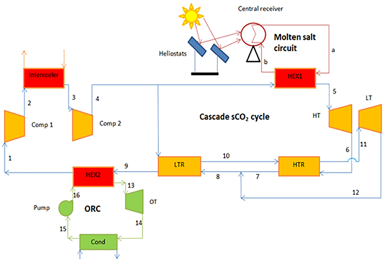
Schematic diagram of SPT driven combined intercooled cascade sCO2and ORC (configuration-1).
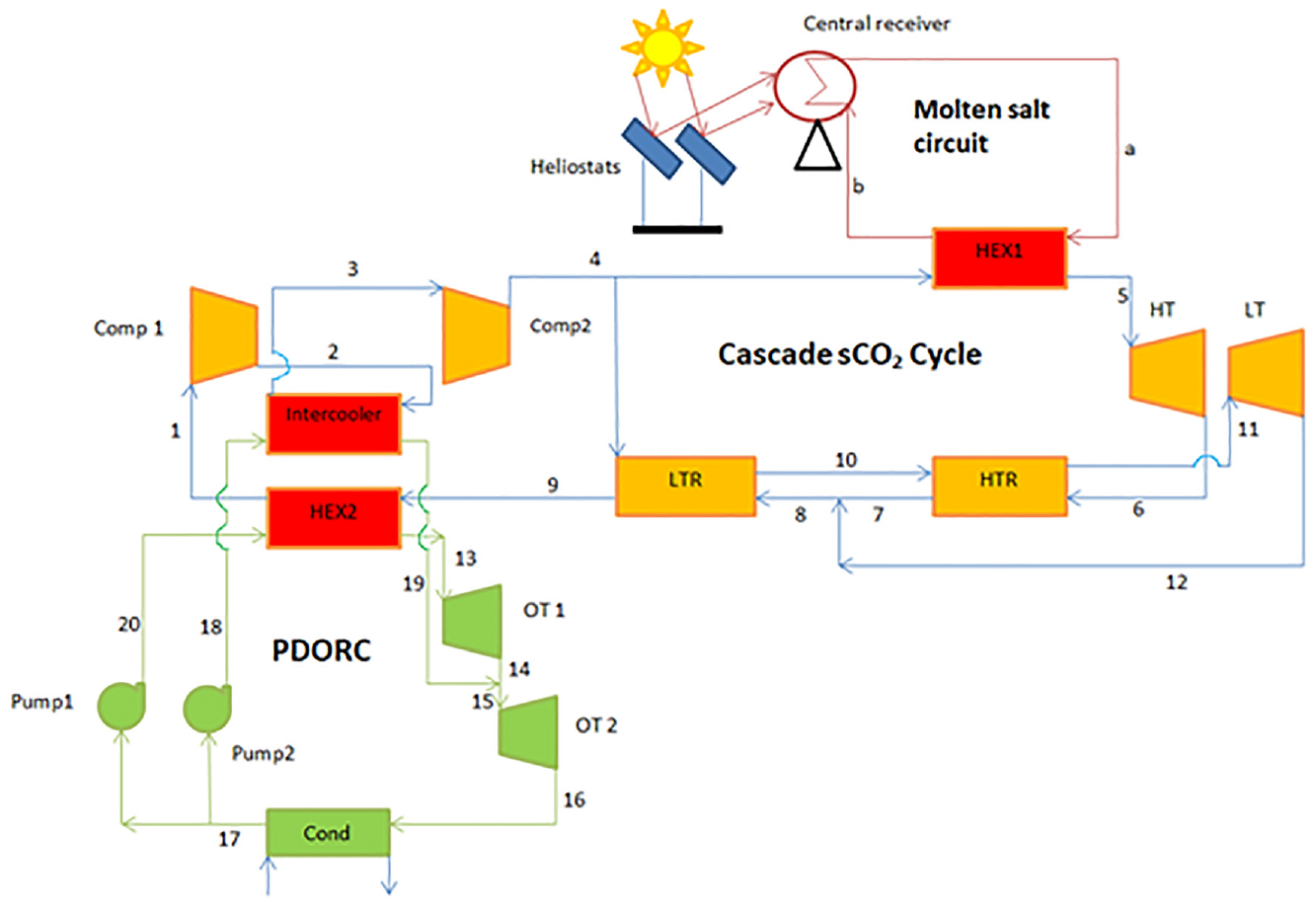
Schematic diagram of SPT driven combined intercooled cascade sCO2 with and PDORC (configuration-2).
In the configuration-1 (Figure 1), as the heat transfer fluid (HTF) the mixture of molten salt has been taken in solar circuit. The sCO2 stream is flowing in the intercooled cascade cycle. After taking the heat through the heat exchanger-1 (HEX1) (state 4–5) sCO2 stream expanded in the high temperature turbine (HT) (state 5–6). Expanded stream contains still lot of heat. It further used to heat the low temperature stream in low temperature recuperator (HTR) (state 6–7), then passes through the low temperature recuperator (LTR) (state 8–9) after mixing with expanded stream by low temperature turbine (LT). After LTR some heat is still remain. This remaining heat is supplied to the ORC via heat exchanger-2 (HEX2) (state 9–1). Further, compressor-1 (Comp 1) (state 1–2) compressed sCO2 stream after it perfectly intercooled (state 2–3), after this stream again compressed in compressor-2 (Comp 2) (state 3–4). After the compressor-2 a part of sCO2 stream goes to LTR (state 4–10) and then passing through the HTR (state 10–11) it was expanded in low temperature turbine (LT) (state 11–12) and remaining part of the stream goes to HEX1 (state 4–5), through the HEX2 the waste heat was absorbed by the ORC by working fluid R1234yf (state 16–13). This stream was expanded through the organic turbine (OT) (state 13–14) and passing through the condenser (state 14–15) where heat was rejected it was passed by the pump (state 15–16). Finally, similarly this repeats again and again.
It would be better if the waste also from the intercooler as well as through HEX2 could be utilized, for this purpose in the configuration-2 instead of basic ORC, the PDORC is applied to utilize the wasted heat from the intercooler and HEX2 simultaneously as shown in Figure 2. After getting the heat through HEX2 (It is possible to call it evaporator-1) (state 20–13) organic working fluid R1234yf (or it can also be written as HFO1234yf) stream is expanded in organic turbine-1 (OT1) (state 13–14), expanded stream mixed with the stream which was coming from the intercooler (It is better to call it evaporator-2) (state 18–19). Total mass of working fluid R1234yf stream is passed through the organic turbine-2 (OT2) (state 15–16). After the condenser (state 16–17) R1234yf stream splits in two parts, through pump-2 (state 17–18) one part goes to recover remaining part of the waste heat. Another part goes to the HEX2 (state 20–13) for recovering the waste heat. Thus PDORC completed and repeated again and again. T-s diagrams of the intercooled cascade sCO2 cycle, basic ORC and PDORC corresponding to the state points are shown in Figures 3 to 5 respectively. Input data for the SPT system has been taken from ref. 1 while data for the combined cycle given in Table 1.
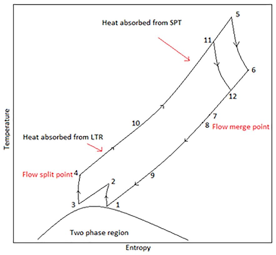
T-s diagram of intercooled cascade sCO2 cycle.
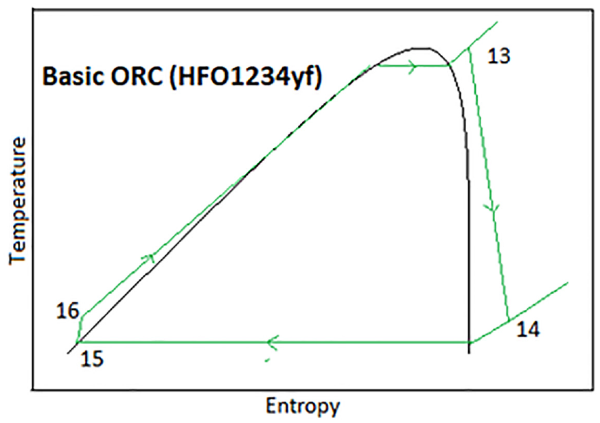
T-s diagram of basic ORC using HFO1234yf (R1234yf) fluid.
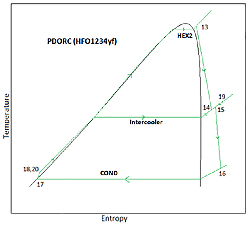
T-s diagram of PDORC using R1234yf (HFO1234yf) fluid.
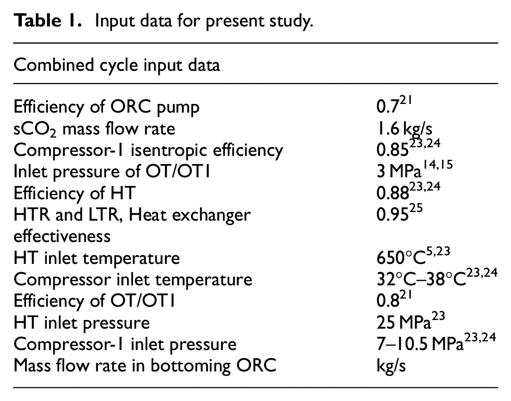
Input data for present study.
Thermodynamic and exergoenvironmental analysis
Assumptions
Following assumptions were considered for the simulation;
A steady state conditions has been considered for the each components. (2) In each component and pipes friction and pressure drop are loss neglected. (4) Change in kinetic and potential energy due to position for the each component is ignored. (5) The 700°C molten salt temperature is fixed at the inlet of HEX1. 24 (6) Temperature inlets to the HEX1is fixed 50°C less than the inlet of molten salt due to thermal losses. 15 (7) R1234yf has been chosen as organic fluid in ORC and PDORC due to its ultra low GWP, ODP and high temperature stability. 21 (9) Mixture of molten salt is considered as HTF in SPT field which thermophysical properties are given in Xu et al. 26
Modeling equations
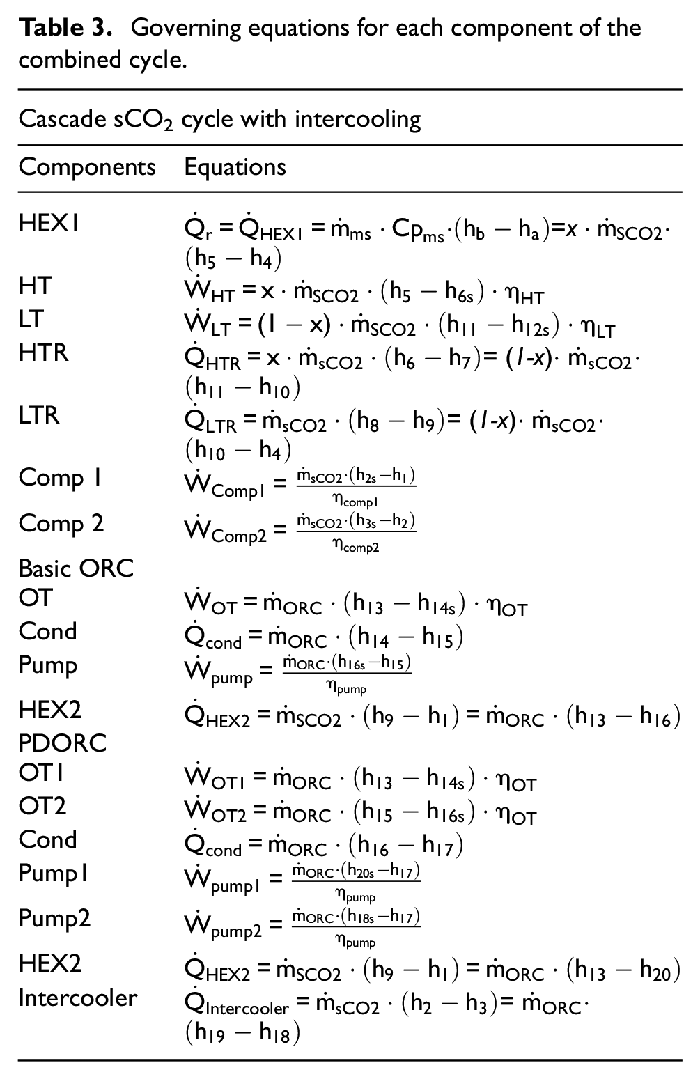
Modeling equations of the given system have been discussed in this part. These equations have been made considering energy balance equations. Also these equations were developed on the basis of given assumptions. Modeling equations of SPT system were developed and listed in Table 2.
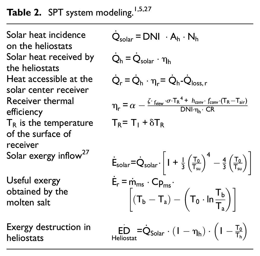
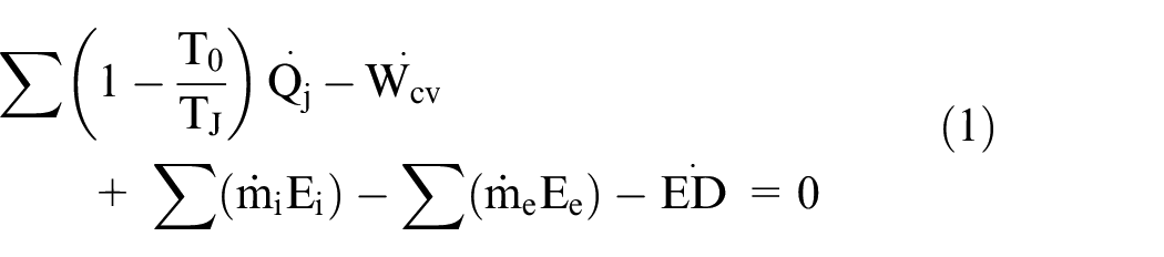
The modeling equations of the heliostat, central receiver and solar exergy are given in Table 2. Exergy is the maximum work obtainable when the any thermal system is brought to its dead conditions isentropically. 5 While exergy balance equation is written;
Where,
After neglecting the chemical exergy in the components due to no change in concentration of the fluids during the process and potential and kinetic energy, at any state specific flow exergy formula is given as5,28;

Thermal modeling equations of combined cycle have been discussed further. Based on the energy balancing equations and control volume approach, equations for the each component of the cycles were developed and listed in Table 3.
Governing equations for each component of the combined cycle.
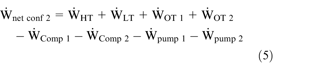
Net power outputs by the different configurations are defined by the equations;


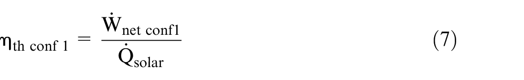
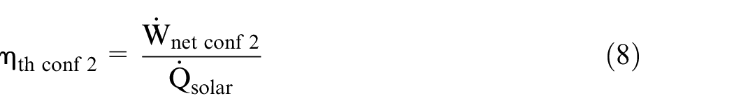
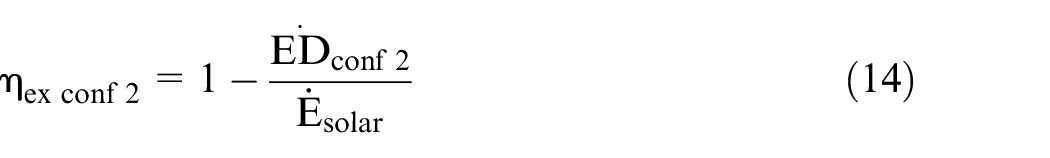
Thermal efficiency of the different configurations powered by the solar energy can be defined as;

Furthermore, in this section it is needed to calculate the rate of exergy destruction for all components to perform exergetic analysis. It is determined by using the equation (1) after assuming no loss in heat. 29
Now total exergy destruction rate for each configuration can be calculated as;
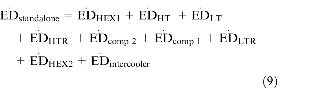
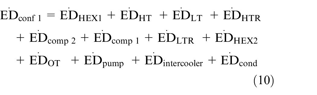
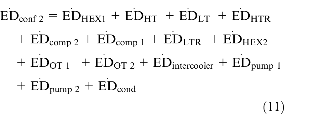
Performance parameters for the solar assisted combined cycles were defined by taking considerations of the various mathematical relations in thermal modeling sections and discussed below;
Exergy efficiencies of different configurations were calculated as28,29;

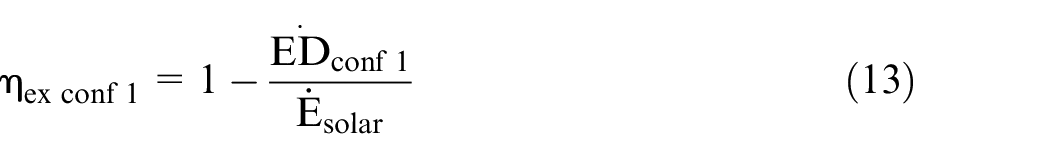
Exergy efficiency formula is also given as 29 ;

Waste heat recovery ratio (WHRR) is another performance parameter. It denotes the capacity to utilize the wasted heat by a cycle. It is expressed as 30 ;

Where,
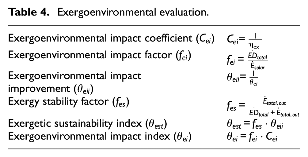
Apart from the thermal analysis, nowadays it is necessary to analyze the impact of power system to the environment to investigate its sustainability. Thermodynamic analyses of power plants that focus solely on energy and exergy are insufficient. Therefore, environmental analysis and sustainability assessment are carried out in the integrated multi-generation systems on the basis of exergy. 31 The path of exergoenvironmental analysis is determined by the impact of exergy destruction rate and exergy efficiency on the surrounded environment. Table 4 lists the most important exergoenvironmental parameters. The exergoenvironmental impact factor has been taken to show how a thermal system affects the environment and how it can be utilized to reduce environmental hazards by minimizing irreversibilities. It was described as the ratio of total exergy destruction to the total available exergy to the inlet of the system. The inverse of exergy efficiency is the exergoenvironmental impact coefficient, and its low value for the researched system is greatly praised. Whether a system is harmful to the environment or not is determined by the exergoenvironmental impact index. The lower the value of the exergoenvironmental impact index, the better the system’s performance. Parameter exergoenvironmental impact improvement is used to determine the system’s relevance to environmental conditions. In contrast to the exergoenvironmental effect index, a higher value of this parameter is thought to be better for the environment. The value of the energy stability factor should be close to “one.” A higher exergetic sustainability value is beneficial to the system. If it is lower, the system under investigation is harmful to the environment. The lower the value of the exergoenvironmental impact index is preferred for the better the system’s performance. The exergoenvironmental analysis was conducted using giving modeling equations and results were calculated by the computational techniques using EES.
Exergoenvironmental evaluation.
Optimization
By adjusting numerous independent variables within an acceptable range, optimization is a procedure for minimizing or maximizing an objective function. If only one function is necessary, single objective optimization is used; if multi-objective optimization is selected where more than one objective are used. Efficiencies, power, cost, released pollutants may be the objective function of the power generation systems. 31 There are various decision variables that affect the objective functions in optimization, hence more independent variables, referred to as degree of freedom, must be chosen. Direct normal irradiation, entry temperature of turbine, inlet temperature of the compressor and heat exchanger effectiveness are all independent variable to be considered for optimization of the system. Thermal efficiency is the main performance parameter for the any thermal power plant. Therefore thermal efficiency is considered as the objective function of the current single objective optimization problem. Therefore the objective of the present optimization is to maximize the thermal efficiency of the system. Method and procedure of the optimization were discussed in “optimization results” section.
Validation of proposed system
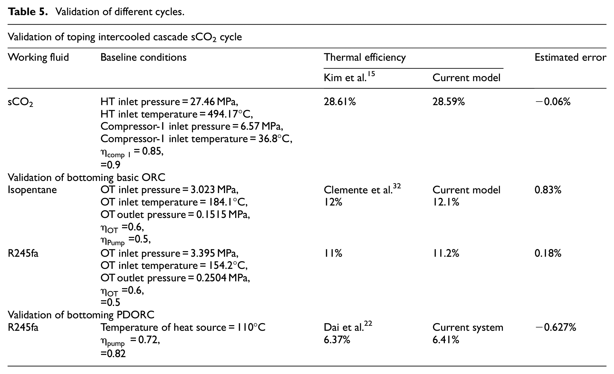
It was necessary to validate the current system to authenticate the proposed model for the further analysis. Separately, all three cycles were validated with different literature are given in the Table 5. Thermal efficiency has been taken as the validation parameter for all three cycles. Cascade sCO2 with intercooling cycle was validated with the previous study Kim et al. 15 The ORC and PDORC were also verified with the study by Clemente et al. 32 and Dai et al. 22 respectively at same input data respective to references. It was seen that all cycle’s thermal efficiency was obtained nearly to the respective literature as displayed in Table 5. Also estimated errors with the previous systems were calculated and listed in the last column of the Table 5. It was seen that estimated error was less than 1%. It means that current system is authenticated and can be used for the further analysis.
Validation of different cycles.
Results and discussion
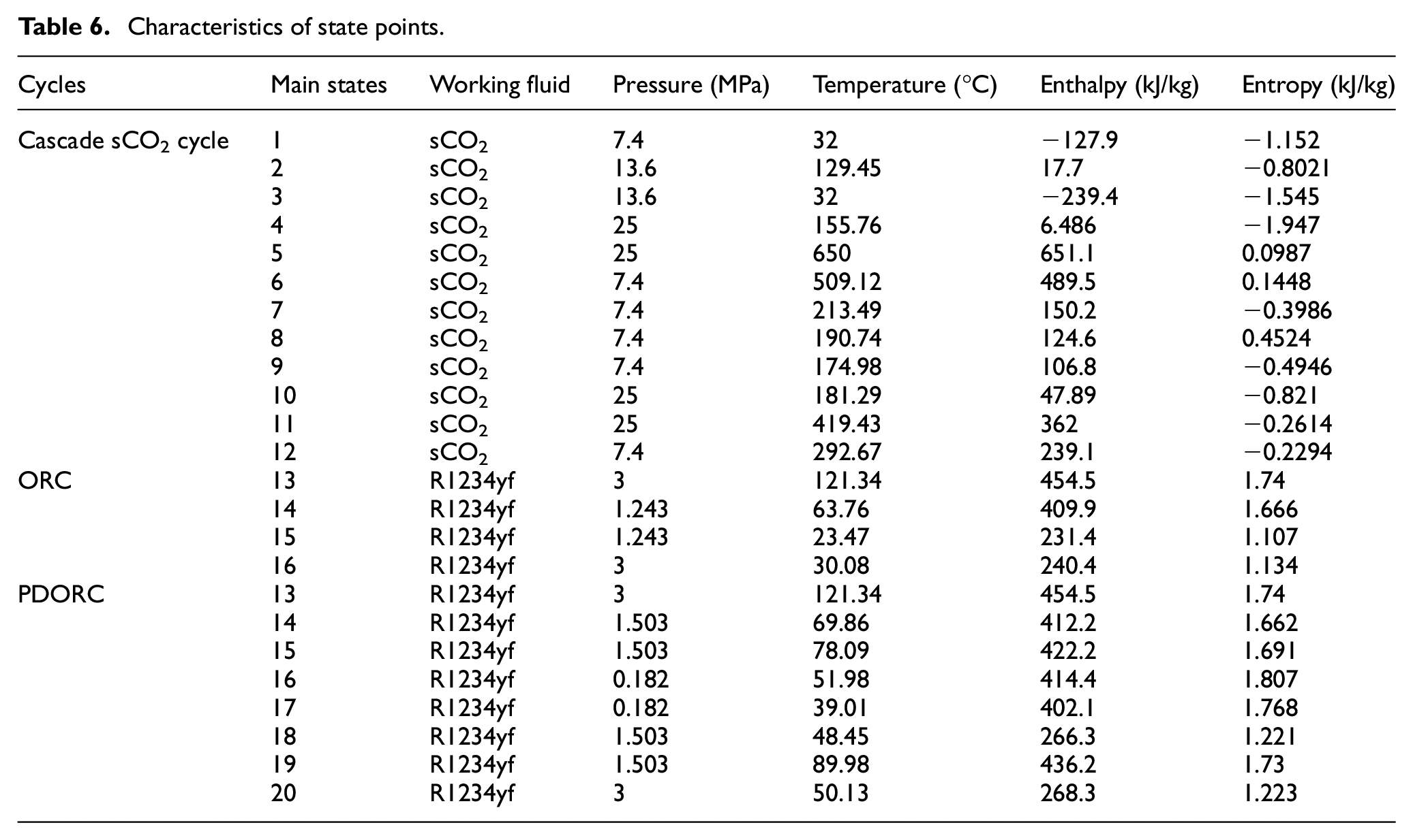
Results were found from the computational analysis in EES taking all input data in consideration are listed in Table 1. Also the characteristic of the main state points are listed in the Table 6. These considered ranges of the independent parameters usually affects the system performance most. Therefore the ranges of the independent parameters were considered from the previous studies.5,19,25,28 Effects of different independent variable were discussed in this section one by one.
Characteristics of state points.
System performance evaluation with solar irradiation
Base condition of solar irradiation has been taken as 850 W/m2as per Indian climate at Mumbai. Since the present study is based on the solar energy. Therefore, it is needed to discuss the effects of solar radiation on performance. The efficiency improved continuously with DNI, because with increase in DNI, rate of energy conversion increased. 30 According to the left axis of Figure 6, maximum exergy efficiency for standalone cycle, configuration-1, and configuration-2 was 69.76%, 70.86%, and 72.98% at the DNI of 950 W/m2. At the DNI of 950 W/m2, the exergy efficiency of the intercooled cascade sCO2 was enhanced by 1.57% and 4.61%, respectively, by integrating the basic ORC and the PDORC. It was seen that improvement in the exergy efficiency with PDORC is more than the basic ORC. Because PDORC recovered more heat compared to the basic ORC due to the double evaporators. Additional heat was recovered from the intercooler by the incorporating the PDORC.
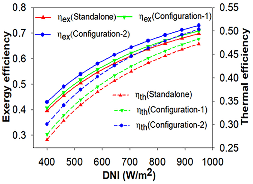
Efficiency variation with the solar irradiation.
Configuration-2 attained the power output and thermal efficiency of 273.3 kW 50.38% respectively, at DNI of 950 W/m2, as shown in Figures 6 and 7. The thermal efficiency and power output curves follow the same pattern as the exergy efficiency curve. This is because thermal efficiency is closely related to exergy efficiency. 29 Increase in solar irradiation from 400 to 950 W/m2, thermal efficiency of the configuration-1, configuration-2 and standalone cycle were increased from 27.89% to 48.3%, 30.06% to 50.38%, and 26.76% to 47.23%, respectively.
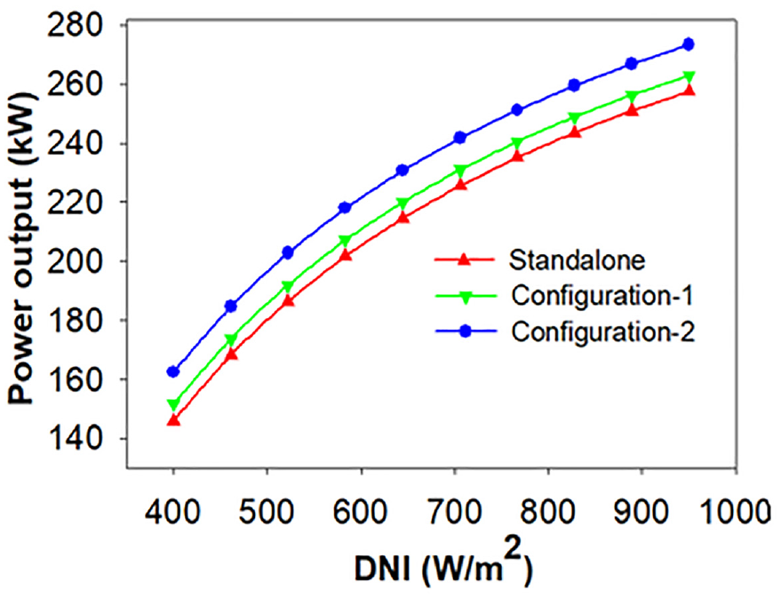
Power output variations with DNI.
Performance evaluation with solar emittance
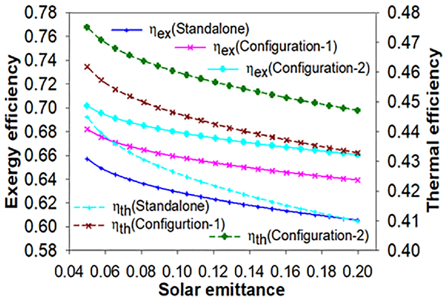
Since receiver performance highly affected with the solar emittance, so it is needed to discuss the impact of solar emittance on the system performance. As efficiencies of the system drop as solar emittance increases seen in Figure 8. The receiver surface temperature is determined by the solar emittance. Efficiency of the receiver falls as solar emittance increases. Its meaning is that higher loss of heat to the environment and, as a result, lesser heat availability to the combined cycle. Consequently, the exergy efficiency and thermal efficiency of the combined cycle are lowered. Increased solar emittance from 0.05 to 0.2 affects configuration-2’s thermal and exergy efficiency by 6.28% and 3.57%, respectively. All of the cycles operate under the identical input conditions, with the exception of bottoming cycles like ORC/PDORC. As a result, the curve pattern is consistent across all combinations. The similar effect of solar emittance was seen in the other two configurations as well.
Solar emittance versus efficiencies.
Performance evaluation with the concentration ratio
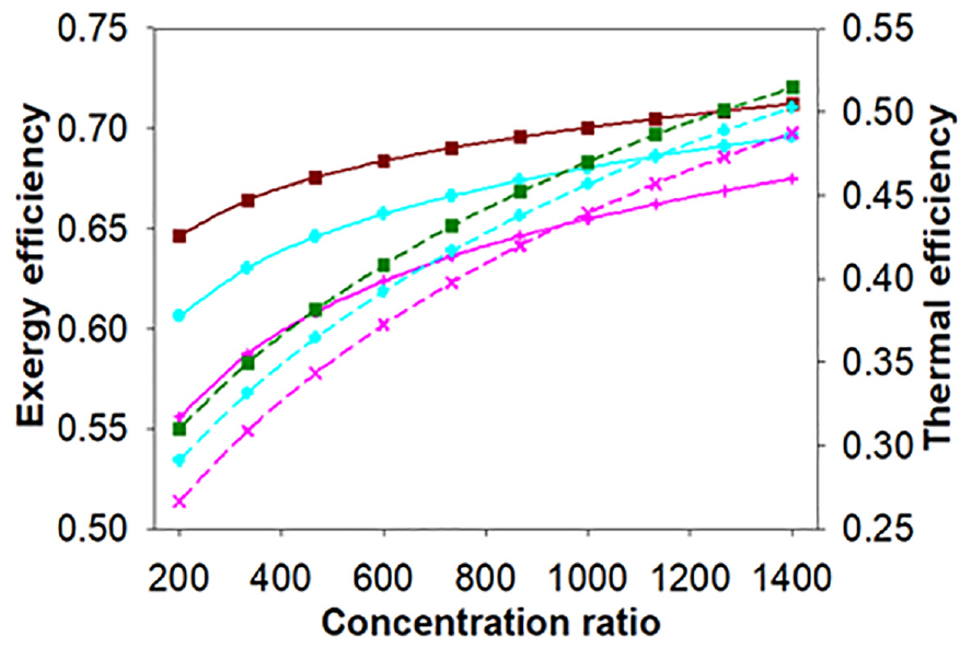
Concentration ratio is also critical parameters to be discussed. Thermodynamic performance of the power system can be affected by the concentration ratio. Efficiencies of the system increased with concentration ratio as can be seen in Figure 9. It can be explained as receiver efficiency increased with the concentration ratio. That increased the outlet temperature of HTF. As it is known, inlet temperature of turbine has direct relation with the receiver outlet temperature. Consequently, as the temperature of the turbine inlet increased, the combined cycle efficiency increased. Once again configuration-2 got highest thermodynamic efficiencies. With improvement in concentration ratio from 200 to 1400, thermal and exergy efficiencies raised by 56.25% and 7.85% and respectively.
Efficiencies variation with the concentration ratio.
HT inlet temperature effect on performance
The temperature of the molten salt has a direct impact on the HT inlet temperature (HTIT). HTIT rises in proportion to the molten salt’s temperature. The heat loss in the solar receiver however increases, as the molten salt temperature rises. As a result, receiver efficiency is reduced. 5 However, in this study, the characteristics of solar system are held constant and are reported in Table 1. The primary goal is thus to compare the thermal performance of the standalone cycle with configuration-1 and configuration-2.
Other input parameters were held fixed while evaluating the impact of HTIT, as seen in Table 1. Thermal performance (efficiencies and power output) have all risen with HTIT, as seen in Figures 10 and 11. Improvement of thermal performance can be explained as HTIT enhanced the enthalpy difference throughout the HT, the output power increases. 15 However, as HTIT grows, efficiencies and power output follow a distinct pattern, as illustrated in Figures 10 and 11. The highest thermal performance was achieved with configuration-2. At 800°C of HTIT, the power production, thermal efficiency and highest exergy efficiency of configuration-2 were 314.9 kW, 51.43% and 71.22% respectively. As a result, performance will higher with higher input thermodynamic properties. However, this much performance is not possible due to material and safety restrictions. Even though both supercritical carbon dioxide and superheated steam cycles had greater input turbine conditions, the sCO2 cycle had a better efficiency. 33
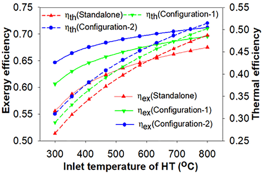
Efficiencies versus inlet temperature of HT.
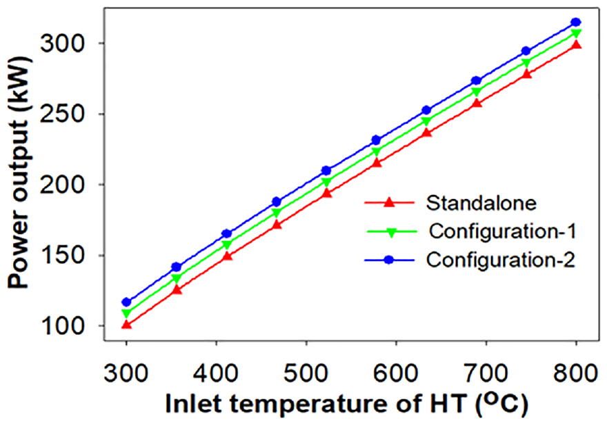
Power output versus inlet temperature of HT.
Performance evaluation with the compressor-1 inlet pressure
Thermodynamic efficiencies of the system rise with the compressor-1 inlet pressure in the subcritical area. Beyond the critical pressure it decreased continuously. This suggests that there is a pressure point where efficiencies and output power are both at their highest levels. Figures 12 and 13 show that the system’s thermal performance (efficiencies and output power) followed bell-shaped curves, because maximum CO2 density at critical pressure causes a decrease in compression power. 34 As a result, more power output power and thus the best efficiencies are achieved. In the case of configuration-2, the best thermal performance was achieved. As shown in Figures 12 and 13, the configuration-2 got the highest values of the output power, thermal, and exergy efficiency 269.4 kW, 49.42% and 73% at 7.74 MPa of optimum pressure.
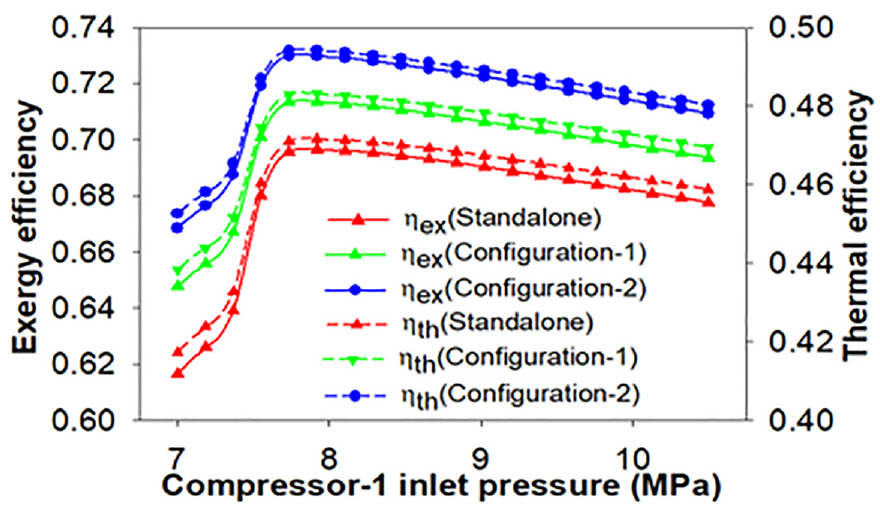
Efficiency variation with compressor-1 inlet pressure.
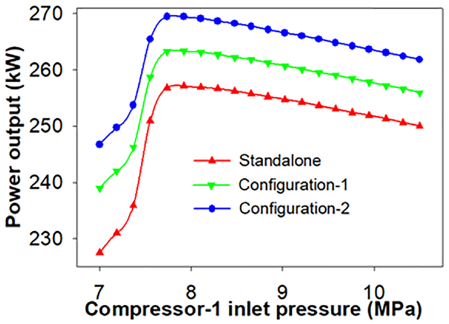
Effect of compressor-1 inlet pressure on power output.
Performance evaluation with compressors inlet temperature
The intercooling has been assumed to be perfect in this investigation. That is, following the compressor-1, the intercooler lowers the sCO2 stream temperature to the compressor-1’s inlet temperature. Performance of the system is influenced by the compressor’s inlet temperature. While maintaining the value of the other input parameter’s constant, as stated in Table 1, the impact of the CsIT on system performance was examined. At 7.5 MPa, the compressor-1’s inlet pressure has already been set. The CsIT is between 32°C and 38°C. The thermal performances of the all configurations were decreased with the CsIT as shown in Figures 14 and 15. The reduction in thermal performance of the system is due to the fact that as the temperature rises over the critical state of CO2, the CO2’s specific heat falls, resulting in a decreased enthalpy at the compressor-1 inlet. 35 This results in a greater enthalpy differential across the compressor, resulting in increased input power. The net power production is consequently decreased. Depending on the SPT parameters, it is known that the heat available at the combined cycle’s input is constant. 12 As a result, the CsIT decreased the combined cycle’s efficiency and net output. Additionally, it was demonstrated that the standalone sCO2 cascade cycle was to blame for the combined system’s overall decline in thermal performance. As seen due to increse in CsIT performance of bottoming ORC also slightly decreased due to slight decrement in turbine output. Therefore, performance of the ORC was not affected by the CsIT variation. It is shown that configuration-2 perfomed well among other configurations. As a result, the configuration-2’s highest exergy efficiency, thermal efficiency, and power output were 70.17%, 47.51%, and 259 kW at 32°C of CsIT, respectively, as revealed in Figures 14 and 15.
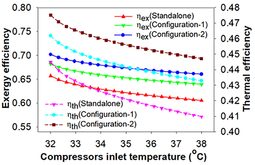
Compressors inlet temperature effects on efficiencies.
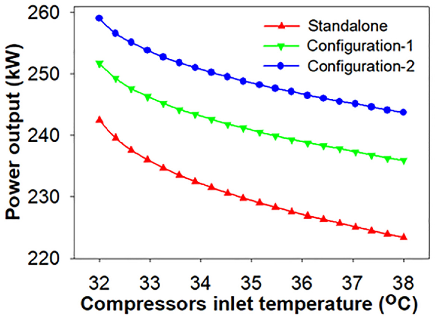
Power output variation with compressors inlet temperature.
Effects on waste heat recovery ratio
Key aim of the current study is to compare the effect of basic ORC (configuration-1) and PDORC (configuration-2) to utilize the wasted heat. That means which system is better to recover the waste heat configuration-1 or configuration-2. WHRR is for the configuration-2 is more than the configuration-1. That means PDORC recovered more heat than basic ORC. At 0.95 effectiveness of HEX2, the highest WHRR for configuration-1 and configuration-2 was 0.1372 and 0.2016, respectively. As a result, the PDORC recovers 46.93% more heat than the ORC, as shown in Figure 16. WHRR increased continuously with the HEX2 effectiveness. As the recovery of waste heat in HEX2 is increased with effectiveness, the increase in WHRR with HEX2 effectiveness can be clarified. As a result, more enthalpy leads to improved output work through the ORC turbine. 12 Consequently, as per the equation (16), WHRR increased.
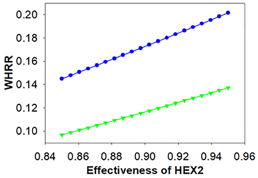
Effect of the effectiveness of HX2 on WHRR.
This part also looked more closely at how the LTR’s effectiveness affected how well the ORC performed. Figure 17 illustrates how the efficiency of the LTR led to a modest increase in WHRR. This is due to the fact that when the LTR’s efficiency rises, the sCO2’s cold stream recovered more heat. As a result, the sCO2 temperature at HEX2’s input is reduced. In other words, it can be claimed that the heat at the HEX2’s inlet is minimal. It lowers the ORC turbine’s inlet temperature. As a result, while using organic working fluids, the ORC turbine’s output power is increased due to its lower inlet temperature. On the other hand at inlet of HEX2 enthalpy also lowered because of lower heat at the HEX2 inlet. The configuration-1’s WHRR is less than the configuration-2’s. The greatest WHRR for configuration-1 and configuration-2 was 0.1775 and 0.1197, respectively, at 0.95 of the LTR effectiveness, as seen in Figure 17.
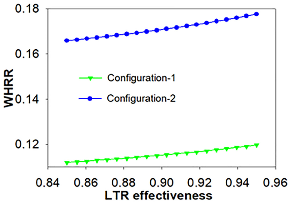
WHRR variation with LTR effectiveness.
Effects on exergoenvironmental parameters
On other hand, exergoenvironmental assessment is used to analyze potential ecological effects of the proposed system. The total rate of exergy destruction and the exergy correlated with every part are determined. Then, based on this exergy destruction, one could make a determination as to whether or not the suggested system will have any negative consequences on the environment. It was seen that configuration-2 is much better on the basis of thermal performance. Therefore, in these section exergoenvironmental parameters for the configuration-2 has been discussed. Furthermore, the exergoenvironmental impact index (
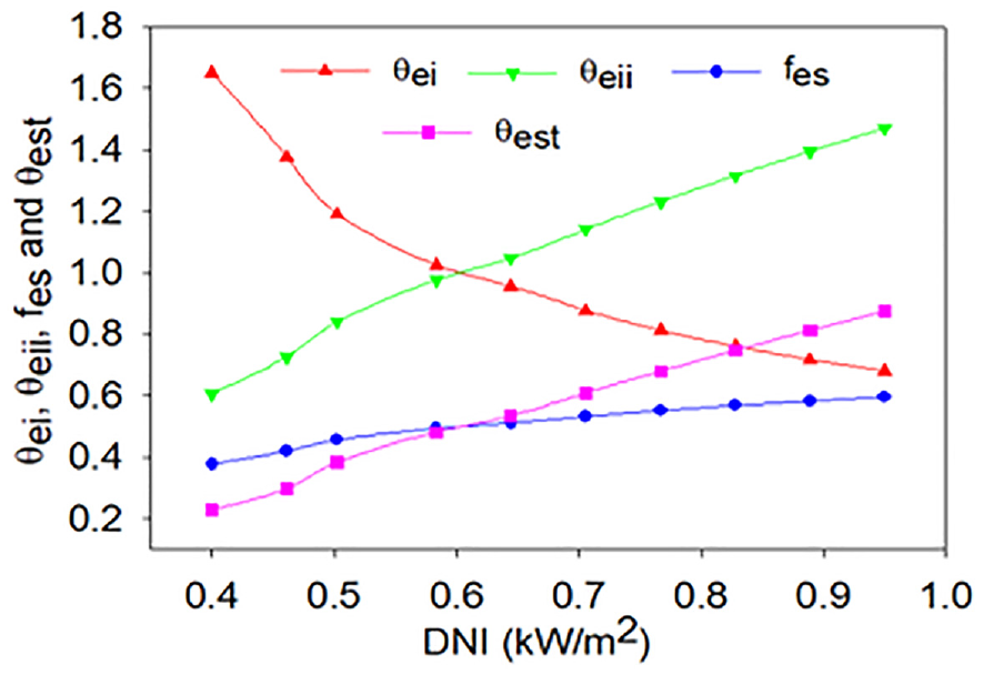
Effects of DNI on exergoenvironmental parameters.
Exergoenvironmental impact index (
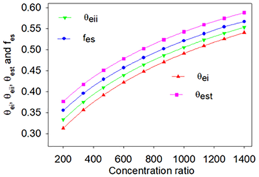
Effects of concentration ratio on exergoenvironmental parameters.
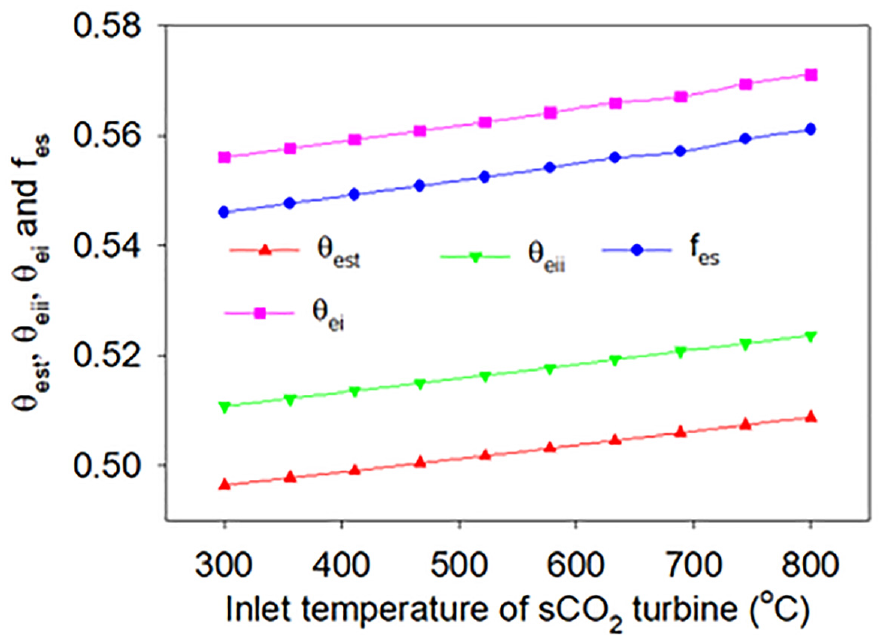
Effect of inlet temperature of sCO2 turbine on exergoenvironmental parameters.
Optimization results
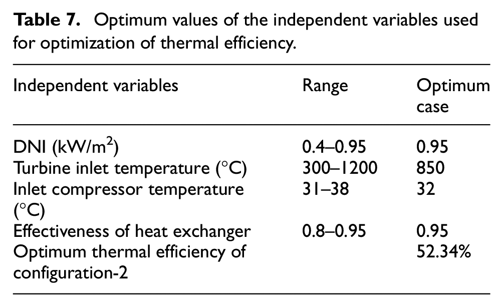
In this part of the research paper, several parameters are optimized to obtain the optimum performance corresponding optimum input parameters values. Using min/max property of EES tool the system has been optimize. Since the from the comparison it was found that configuration-2 gave the highest cycle thermal efficiency among the two configurations such that configuration-1 and standalone cycle. Therefore the thermal efficiency of the configuration-2 was considered as the objective function of the present single objective optimization problem. Table 7 lists the different factors with their range, system boundaries and its optimum values over the optimized thermal efficiency of the combined power plant. The major purpose of this study is to maximize the integrated system’s thermal efficiency, which is calculated using 550 equations, 131 iterations, and 201 blocks in 4.5 s. From the previous study Khatoon and Kim 5 and Al-Sulaiman 28 it was found that DNI, turbine inlet temperature, inlet compressor temperature, and effectiveness of heat exchanger were the most critical parameters that influence the performance of the combined system. Therefore, these four variables were selected as independent variable and their range to determine how they influence the overall thermal efficiency of the system.
Optimum values of the independent variables used for optimization of thermal efficiency.
The structure and the solution of the present study have been explained by the flow chart as shown in diagram Figure 21.
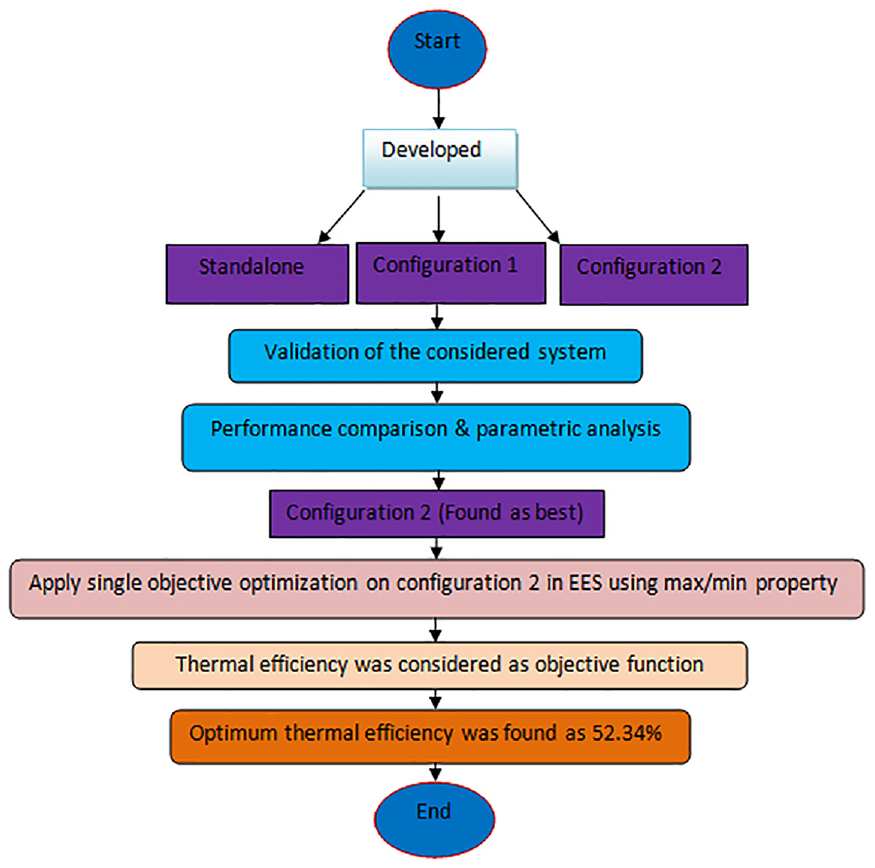
Flow chart for the structure and the solution of the present study.
Conclusions
From the result and discussions sections various conclusions were drawn.
Thermal performance of the proposed cycles was improved with solar irradiation. The standalone cycle, configuration-1 and configuration-2 show maximum exergy efficiency of 69.76%, 70.86%, and 72.98% respectively at the 950 W/m2 of DNI.
By incorporating the basic ORC and the PDORC to the intercooled cascade sCO2 cycle, exergy efficiency were improved by 1.57% and 4.61% while thermal efficiency improved by 2.26% and 6.66% respectively at DNI of 950 W/m2.
System performance falls as solar emittance increases, but increases when the concentration ratio increases. As a result, in order to improve the combined cycle’s performance, the solar emittance must be reduced and the concentration ratio must be increased.
The highest output power, thermal efficiency and exergy efficiency of the configuration-2 were achieved as 269.4 kW, 49.42% and 73% respectively, 7.74 MPa of optimum pressure of compressor-1 inlet pressure.
At 0.95 of LTR effectiveness, the maximum WHRR for configuration-1 and configuration-2 was 0.1197 and 0.1775, respectively.
The PDORC recovered 48.28% more waste heat than the basic ORC. Therefore, configuration-2 is more suitable to recover the waste heat completely.
Exergoenvironmental impact index decreases from 1.6504 to 0.6801 with increase in DNI while the exergetic stability factor increase from 0.3773 to 0.5952 with DNI.
Optimum thermal efficiency of configuration-2 was found 52.34%.
Finally, it was highly recommended to design the SPT system carefully to obtain the best thermal of the SPT integrated cycle.
In future the exergoeconomic, cost analysis and the life cycle assessment of the current power system can be performed for actual installation for power production.
Footnotes
Appendix
Declaration of conflicting interests
The author(s) declared no potential conflicts of interest with respect to the research, authorship, and/or publication of this article.
Funding
The author(s) received no financial support for the research, authorship, and/or publication of this article.