
Abstract
This work presents the characteristics of a solar thermal tower power plant in two different places (Seville and Dubai) using three different HTFs (NaNO3-KNO3, KCl-MgCl2 and Li2CO3-Na2CO3-K2CO3) and three different power cycles (Rankine, sCO2 Recompression and sCO2 Partial cooling cycles). An indirect configuration is considered for the Gemasolar power plant. Detailed modelling is carried out for the conversion of incident power on the heliostat to the output electricity. Optimization of the cycle is carried out to determine the most promising cycle configuration for efficiency. The results showed that for the Gemasolar power plant configuration, the performance of the KCl-MgCl2 based plant was poorest amongst all. NaNO3-KNO3 based plant has shown good performance with the Rankine cycle but plant having Li2CO3-Na2CO3-K2CO3 as HTF was best for all three cycles. Partial cooling was the best performing cycle at both locations with all three HTFs. Placing the Seville Plant in Dubai has improved the efficiency from 23.56% to 24.33%, a capacity factor improvement of 21 and 52 GW additional power is generated. The optimization of the plant in Dubai has shown further improvements. The efficiency is improved, the Capacity factor is increased by 31.2 and 77.8 GW of additional electricity is produced.
Introduction
Two main problems faced by our society are a shortage of power and environmental pollution. To overcome these problems study of renewable and sustainable energy should be the top priority.1–4 Concentrated Solar Power (CSP) technology is one of the most promising technologies that can use renewable energy to generate electricity thus meeting energy demand and sustainability of the environment. Using this technology direct sunlight is converted into renewable electricity without emission of greenhouse gasses.5,6 Concentrated solar technologies with integrated Thermal Energy Storage (TES) allow a centralized solar energy generation independent of weather conditions and generation is possible during no sun hours.7–9 Most modern CSP stations are based on Solar Thermal Tower Power Plant (STTPP) stations, since these are better suited to achieve very high temperatures than other CSP stations, thus increasing the efficiency of heat to electricity conversion. 10 STTPP is one of the concentrating solar energy technologies that generate electricity by concentrating the solar radiation on the receiver placed on top of the tower that is surrounded by the heliostat field.11,12 A typical STTPP consists of four main components: a solar concentrating field, a receiver, a High Temperature Fluid (HTF) storage system and a conventional power plant.13–16 STTPP are of two main configurations: The first one is the Direct Steam Generation (DSG) system, in which heat is absorbed by water in the receiver and is directly converted into steam for power generation, for example, Ivanpah solar thermal plant in California.17,18 The second is the indirect configuration in which heat is transferred from the receiver to HTF and then transferred to the power block for power generation, for example, Gemasolar plant in Seville Spain.19,20
Modern receiver systems for commercial STTPP use the latest technology so that an outlet temperature greater than 700°C can be achieved. The design and study of receivers with particles, gases and liquids as HTF that can reach such high temperatures were discussed by many researchers.21–24 Particle-based technologies include direct irradiative design (obstructed, free fall and centrifugal) and enclosed design (fluidized and fed by gravity).25,26 New gas receivers include micro-channel design and optical trapping configurations due to which surface area of the receiver is increased, which in turn increases heat transfer and absorption of solar energy, thereby increasing fluxes as well as pressures.27,28 Receivers having liquid HTF include high-temperature salts like halide (chloride and fluoride) and carbonate salts and some liquid metals (lead, bismuth and sodium).29–31
The HTF is an important part of the transfer and storage of thermal energy in a centralized solar system. Due to its thermo-physical nature, the salt mixture can be used as a high-temperature HTF. CSP operation requires a lot of HTF; therefore, it is important to choose the most suitable HTF to reduce costs when it comes to performance. The most commonly used salt as HTF is usually solar salt (60% NaNO3– 40% KNO3), 32 which is used in commercial plants like the Gemasolar power plant and Crescent Dunes power plants.19,33,34 Some salts are especially suitable for high-temperature processes to get higher efficiencies, for example, Li2CO3-Na2CO3-K2CO3, KCl-MgCl2, etc. Li2CO3-Na2CO3-K2CO3 is suitable for high-temperature operations between 450°C and 700°C. Liu et al. 31 enlisted the thermo-physical properties of Li2CO3-Na2CO3-K2CO3 salts from 450°C to 600°C. Li2CO3-Na2CO3-K2CO3 can meet the requirements of high-temperature fluids that can be used as HTF. 30 Also, KCl-MgCl2 can be used as HTF for high-temperature storage and heat transfer applications for CSP operating at high temperatures up to 800°C.35,36
For CSP applications, a combined cycle can be used for power generation. Brayton cycle is used as a primary and Rankine cycle is used as a secondary cycle for the solar tower power plant using rock bed storage. The overall efficiency of 69.2% is achieved using this cycle.37,38 sCO2 Brayton cycle is recommended39–41 as a replacement for Rankine and other gas cycles as it has different advantages like compressibility of CO2 in incompressible regions thus less work is required. After the critical point (31°C, 7.38 MPa), CO2 remains dense throughout the power system and smaller equipment like turbine and heat exchanger are required compared to conventional cycles. It can be used in the sCO2 Brayton cycle for the CSP cycle in the drought region due to its dry cooling possibility. Various cycle designs have been proposed for the sCO2 Brayton cycle, including Recompression cycle, Pre-compression cycle, Partial cooling cycle, an Inter cooling cycle and a simple recuperation cycle, etc.42–44 Higher conversion efficiencies can be achieved using high-temperature HTFs as higher temperatures increase the efficiencies of the sCO2 cycle. Recompression with Main Compressor Inter-cooling (RMCI) selected has shown the best solar to power conversion efficiency, that is, 24.5% at maximum temperature value of 750°C using KCl-MgCl2 as HTF. 36
Plant layout
Figure 1 shows the installed components of STTPP evaluated in this work. The solar power station has a Solar Tower (ST) with one receiver placed at the top to collect thermal energy concentrated by the heliostat field placed all around. The heat is transferred to the HTF by the receiver, a TES system with two units is placed to store the excess HTF in peak hours that can be used in no sun hours thus increasing the power generation. The heat from the power unit to the environment is removed by the air cooler. This is because only a limited amount of water is available in areas with high solar radiation. Two alternative HTFs, KCl-MgCl2 and Li2CO3-Na2CO3-K2CO3 are considered that can withstand higher temperatures and compared results of both HTFs with NaNO3-KNO3. A comparative analysis between HTFs shows the most promising specifications, which can explain the advantages and disadvantages of each fluid choice. Table 1 shows the main and conditional characteristics of the three considered HTFs. These three molten salts have different thermal properties as enlisted in Table 1 and for the comparison purpose same plant configuration is considered for all three HTFs. Comparison of these HTFs, that is, NaNO3-KNO3, KCl-MgCl2 and Li2CO3-Na2CO3-K2CO3 is carried out considering the same incident power on the heliostat field.

Gemasolar solar thermal tower power plant drawn using GoogleEarthPro (left), different power cycle under consideration (right).

A detailed comparison is carried out considering solar to electric efficiency as a criterion to compare different HTFs. Total efficiency ηtotal of the solar thermal power plant is the amount of net energy produced from the solar energy incident on the heliostat field of the STTPP.
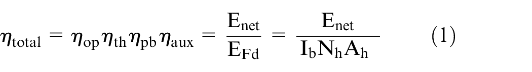
Optical efficiency ηop of the solar thermal power plant is the amount of energy converged onto the receiver from the solar energy incident on the heliostat field. This depends upon total optical losses of the heliostat field Eop,loss.

Receiver thermal efficiency ηth of the solar thermal power plant is the amount of energy absorbed by the HTF from the total energy incident on the receiver. This depends upon total convection and emission losses of the receiver Eth,loss.

Power block efficiency ηpb of the solar thermal power plant is the amount of the receiver’s absorbed energy converted to the electrical output of the power block. This depends upon total power block losses Epb,loss of the solar thermal power plant.

Auxiliary efficiency ηaux of the solar thermal power plant is the amount of electricity dispatched to the grid from the electrical output of the power block. This depends upon power consumption of the plant auxiliaries Eaux,loss like power consumed by heliostats’ motors, receiver and tower HTF pumps, TES HTF pumps and condenser system of the solar thermal power plant.

Two different locations are selected for these comparisons so that variations in Direct Normal Irradiance (DNI) and the corresponding maximum temperature’s effect can be calculated accordingly. At first same layout is kept for both locations but later optimization of the receiver, tower and field is carried out for the second location to consider DNI variations into account from different field layout. For comparison in ideal conditions, it was assumed that total heliostat availability at all times, as well as no soiling considerations, are taken in this research. This will later be useful in finding the maximum possible receiver wall temperature. Later the results are enlisted considering the availability and soiling of heliostats.
Modelling and methodology
This section includes details of modelling and procedure used to evaluate plant performance during the conversion of solar energy into electrical energy.
Field layout
The field layout design should take full advantage of the HTF features described in this article. The key feature is the maximum heat flux incident on the receiver supported by NaNO3-KNO3, KCl-MgCl2 and Li2CO3-Na2CO3-K2CO3 receiver is set to be 2130 kW/m2. At first heliostat layout and receiver used will be based on the Gemasolar thermal tower power plant. Afterward optimization of the solar field layout will be carried out and this will include changing the solar field size, reducing the size of the receiver, varying the height of the tower on which the receiver is placed.
The Google Earth Pro and SolarPilot software are used for modelling the solar field layout of the Gemasolar tower plant in Seville to get the corresponding flux patterns on the receiver. The project was developed by reversing the solar field of the Seville using Google Earth Pro. The boundaries of the solar field, inner circle, tower position and pathways to simulate the exact layout field are plotted in Google Earth Pro. These boundaries are imported in the solar pilot for placing heliostats within layouts boundary limits. The summer solstice is selected for Sun location at the design point, a design point DNI of 970 W/m2 is assumed and the solar multiple of 2.8. A solar field similar to the Gemasolar power plant is formulated into the SolarPilot. The dimensions of the receiver and the heliostats are kept the same for all three molten salts KCl-MgCl2, NaNO3-KNO3 and Li2CO3-Na2CO3-K2CO3. Also, aspect ratio, total thermal power to receiver (193 MW), and tower height are kept the same. Figure 2 shows the final design of the heliostat field and the key features of the solar field are enlisted in Table 2. In addition to the heliostat layout and visual efficiency, the Solar Pilot also provides a heat flux map for the receiver shown in Figure 3 for the plant in Seville Spain, and Figure 4 for the plant in Dubai UAE.

Gemasolar power plant layout (left): GoogleEarth pro (right): solar pilot.
Parameters of the receiver of Gemasolar solar thermal power plant on 20th March at 12:00 h.


Map of incident Flux on the receiver on the 20th March at 12:00 h in Seville (Spain).
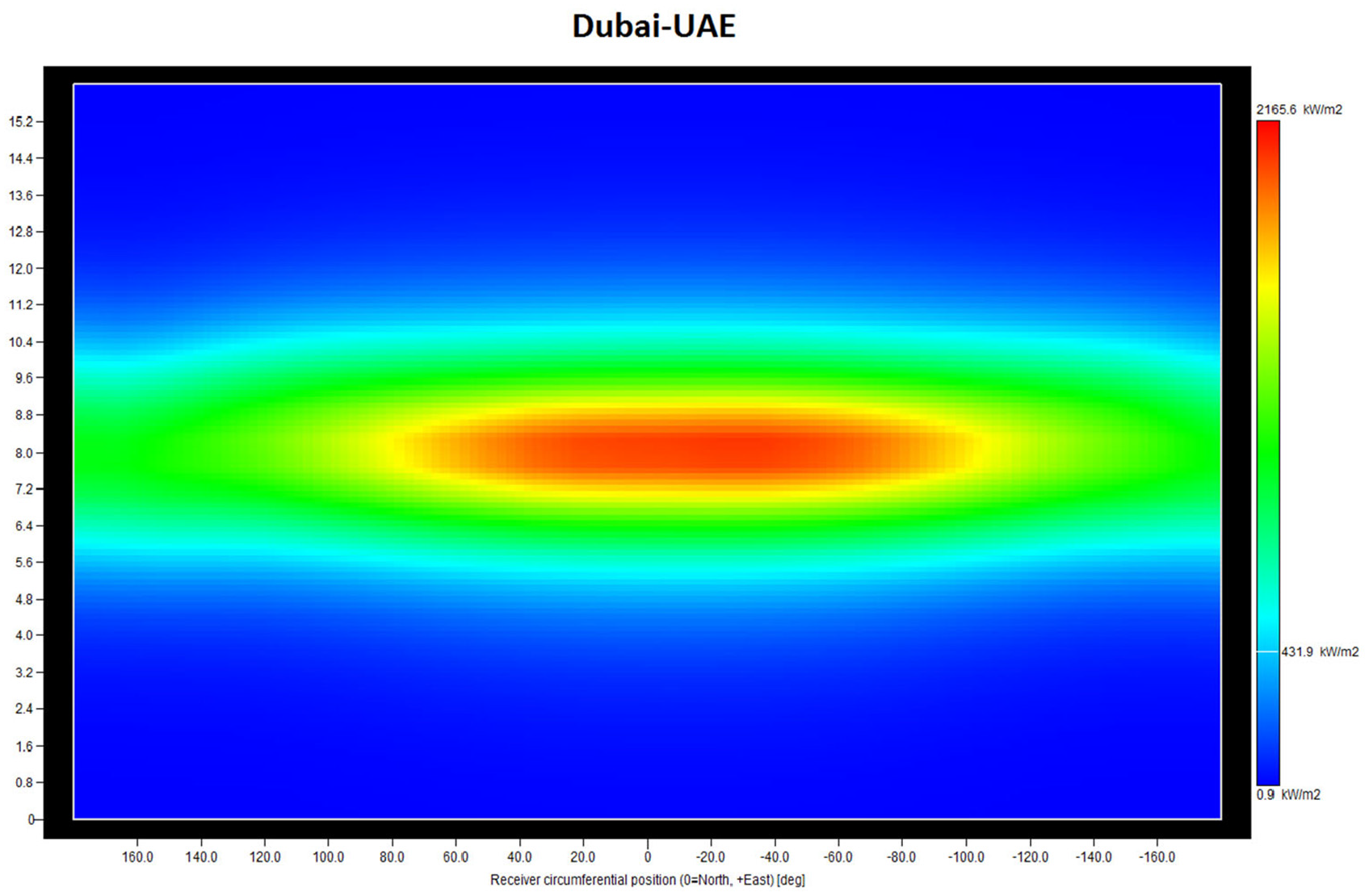
Map of incident Flux on the receiver on the 20th March at 12:00 h in Dubai (UAE).
Receiver design
The external receiver selected comprises of many panels attached in series. Each panel consists of several vertical tubes placed parallel to the axis of the tower. These panels are placed all around the receiver and are connected by connecting attachments at the top and bottom. To reduce the overheating of the tubes, the cold HTF inlet is located on the northern side of the receiver. Considering the assumption that the power plant is situated north of the Hemisphere with maximum heat flux is incident on the same side. The HTF entering the receiver is divided into two paths and each path flows to one quarter on one half and then crosses to flow through the next quarter on the other half of the receiver. At the outflow, these streams combine again from where it is sent to HTF storage. By changing the mass flow rate of the HTF on both sides of the receiver, the output temperature is controlled. Due to the daily uneven distribution of heat flux on the receiver, in most cases, the two different mass flow rate loops are formed. The shape and flow path of the receiver is based on the thermophysical properties of HTF and should be optimized to reduce pressure loss in the tubes and increase efficiency. The three types of HTFs, NaNO3-KNO3, KCl-MgCl2 and Li2CO3-Na2CO3-K2CO3 in this study have different characteristics that affect the flow rate and heat transfer process. In previous studies, the receiver shape of the Gemasolar power station was also determined to be suitable for use with KCl-MgCl2 as HTF due to the physical and thermal similarities of the mixture of salts and solar salt. 36 Table 3 shows the detailed characteristics of the receiver.
Solar receiver main parameters.

Heat losses in the receiver are estimated using a simplified thermal resistance model. A receiver model can predict performance based on the working temperature of various HTFs. This model estimates the thermal losses by using an equivalent resistance network to calculate radiative losses. Based on the input conditions of the HTF, after the HTF runs through each flow path’s panels, each panel is divided into upright sections and the energy balance of each section is analysed. Various studies are already conducted in this regard using solar salt as HTF on Gemasolar plant conditions. 36 In some previous studies, 46 the thermal performance of the receiver extended at high HTF temperature was estimated based on the simplified model. In the present study, this approach is not considered as this is not useful in yearly calculations due to poor performance.
Thermal energy storage and piping
In this study, two-tank thermal storage of 15 h is considered to have cold and hot tank heaters. The HTF storage tank is kept at atmospheric pressure because its size is large and high pressurization goes uneconomical and HTF minimum height is set to 1 m. TES will help balance the plant in transient conditions like haze, cloudy as well as producing electricity during the night when no sun is available. Since HTF needs to be pumped to the top of the tower in the receiver from the tanks, a pumping system is required to provide ground pressure and also compensates for pressure losses in pipes and receivers.
Power cycle description
An extensive description of carbon dioxide as a working fluid and, possibly, the inclusion as HTF in power plants is already provided.42,43 Various sCO2 cycles, some of which were preheating, reheating, pre-cooling or inter-cooling are already modelled and compared with each other, as well as with the Brayton cycle and Rankine cycle. Overall, due to the simple design of the Brayton cycle compared to the Rankine cycle and higher efficiency at low pressure/high temperature, it is of great potential in the CO2 cycle. The latter is due to the effect of low-pressure circulation due to the low compression ratio of carbon dioxide at critical points.42,43
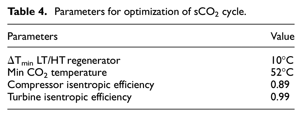
Three cycles are considered for this study including one steam (Rankine cycle) and two sCO2 cycles: Recompression cycle (sCO2-R) and Partial cooling cycle (sCO2-P). In both cases, CO2 leaving the compressor is cooled (regenerated) in the heat exchanger by heating the cold CO2 coming out from the turbine; this reduces the necessary external heat input and increases efficiency. In the sCO2-P configuration, the main compressor is divided into two different stages; the first stage with the intercooler reduces the temperature of carbon dioxide to the minimum temperature of the cycle before compression in the second stage occurs. In terms of flow distribution, the location where the splitter is located is different for sCO2-R and sCO2-P. In the sCO2-P configuration, the splitter is located after the first stage of the main compressor, secondary current bypass the intercooler, and the main compressor’s second stage. Instead, it is compressed into the secondary compressor before mixing it with the major currents. In sCO2-R splitter is located before pre-cooler and heat rejection is not carried out for the secondary stream.36,46 Based on a preliminary economic and technical assessment, the air cooler is designed with a minimum temperature difference of 10°C. The Primary heat exchanger (PHX) is designed with a temperature difference of 15°C between sCO2 and HTF. Given a calculated ambient temperature of 37°C, the minimum CO2 temperature is set to 52°C. Optimization of the cycle is carried out based on PHX temperature difference, air-cooler temperature and HTF in and out temperatures for each cycle to get an output of 30.4 MW and efficiency close to 44%. Details of different parameters on which, optimization is based are enlisted in Table 4.
Parameters for optimization of sCO2 cycle.
Annual energy
This section presents methods for assessing annual electricity generation and the corresponding solar energy efficiency for electrical production. As already discussed that simple model calculations were not carried out due to poor performance compared to other cases, simple processes were not considered in this analysis. In previous studies, it is also concluded that simple cycle consideration resulted in limited economic benefits.46,47 The analysis is performed at two different locations, that is, Seville and Dubai to illustrate the plant and working fluid performance under different DNI conditions. Weather files for both the locations are based on the PVGIS data. 48 The details of the DNI values are plotted in Figure 5 for both locations and details are enlisted in Table 2 (The DNI in Seville is 4.86 kWh/m2/day and the DNI in Dubai is 6.71 kWh/m2/day). The solar multiple for Seville is 2.8 as used in previous work,36,46 the same is then used for Dubai as the same plant is placed there.

Monthly data of weather file (for 1 year) of beam irradiance-DNI (W/m2) and global irradiance-GHI (W/m2) for Seville-Spain (left) and Dubai-UAE (right).
An annual analysis is performed by determining the efficiencies of the optical, thermal and conversion cycles based on the position of the sun, sunlight and ambient temperature. By compiling an hourly summary of environmental conditions during the year, the change in yield can be calculated for a certain hour to characterize the annual yield. Optical efficiency depends on the zenith and azimuth of the Sun and the plot of both locations is shown in Figure 6.

Field optical efficiency for the NaNO3-KNO3 receiver as a function of Azimuth and Zenith for Seville-Spain (left) and Dubai-UAE (right).
After evaluating the optical efficiency at different places of the sun, the thermal efficiency of the system can be determined at both locations. In principle, the thermal efficiency of each point of sunlight and radiation should be calculated by year. One way to present it is in the form of daily maximum thermal efficiency and an average for the whole year can be calculated. Figure 7 shows the average daily max for different HTF receiver in Seville. It is evident from the figure that the NaNO3-KNO3 receiver shows the highest average daily max receiver thermal efficiency compared to the other two receivers. One of the reasons is that it operates at lower temperatures (Ranges from 450°C to 575°C) compared to others that have higher temperatures, that is, Li2CO3-Na2CO3-K2CO3 (Ranges from 600°C to 700°C) and KCl-MgCl2 (Ranges from 600°C to 850°C). It is also clear from Figure 7 that an increase in temperature results in thermal losses increase and a decrease in efficiency and the same trajectory is observed in all the receivers.
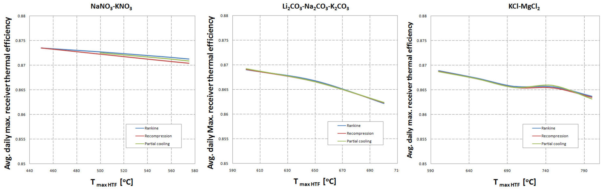
Average daily maximum receiver thermal efficiency of the receiver as a function of HTF maximum temperature in Seville (Spain).
Next in the calculation is to calculate the efficiency of the power cycle which varies for all three cycles considered. This depends upon the conversion of thermal energy absorbed by the receiver to the electrical energy. Power consumed by different entities of the plant is deducted to calculate the final net energy of the Plant. This deduction includes consideration of
Power consumed for circulation of HTF by Thermal energy storage pumps, pumping HTF to the receiver,
Power consumed by the condenser operation,
Power consumed by heliostats’ drives and other fixed loads.
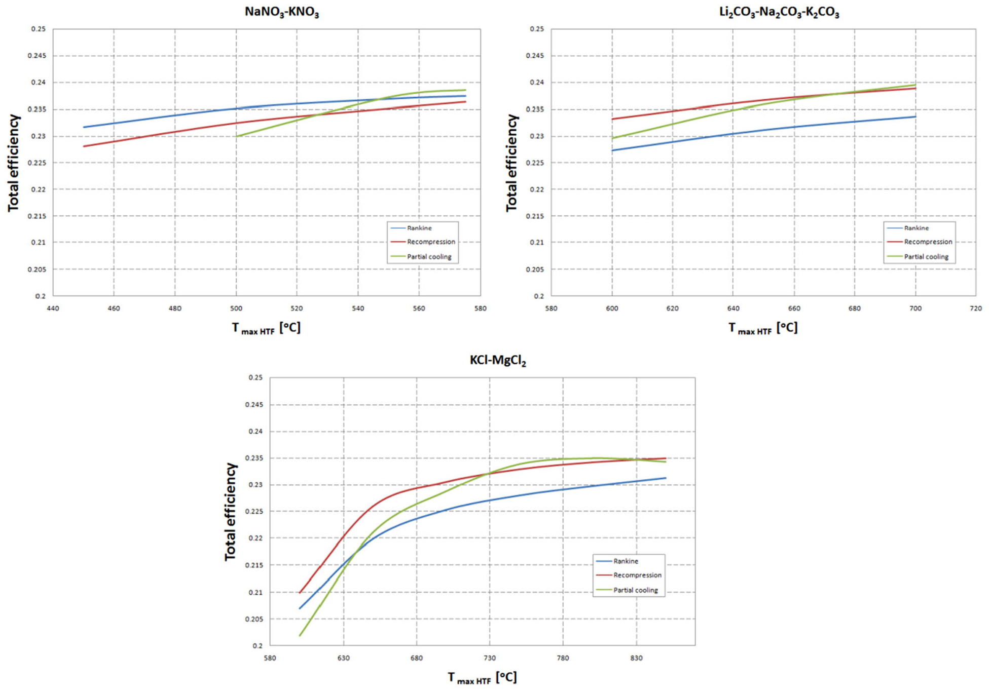
Figure 8 shows three curves of the total annual efficiency of different cycles depending upon the maximum temperature of the HTF for all three HTFs considered in Seville. One thing that is common in all these charts is that an increase in the HTF temperature increases the total efficiency of the plant. In Seville, the efficiency of the Rankine cycle is maximum with NaNO3-KNO3 while other salts have not performed well with the Rankine cycle. The Recompression cycle shows a good efficiency at a higher temperature for both Li2CO3-Na2CO3-K2CO3 and NaNO3-KNO3 but relatively lower efficiency with KCl-MgCl2. The Partial cooling cycle has performed well as the temperature of the HTF increase. For all three HTF at the max temperature, it has the maximum efficiency. The Partial cooling cycle has shown maximum efficiency with Li2CO3-Na2CO3-K2CO3 at 700°C which is a little ahead of its efficiency with NaNO3-KNO3. The efficiency of the Partial cooling cycle is low with KCl-MgCl2 but still the best among all three cycles.

Total efficiency of the plant as a function of HTF maximum temperature in Seville (Spain).
Plant in Seville with NaNO3-KNO3 as HTF is best with both Rankine and Partial cooling cycle at 575°C having an efficiency of 23.5%. But for Recompression, it is a little low, that is, 23.35% due to lower power block efficiency and least auxiliary efficiency of the Recompression cycle. The power block efficiency of the Partial cooling cycle is also less due to low HTF max temperature but it has shown high total efficiency due to lower parasitic losses. Plant in Seville with Li2CO3-Na2CO3-K2CO3 as HTF has shown good performance with Recompression and Partial cooling cycle at 700°C with efficiencies 23.44% and 23.56%, respectively. This is due to higher power block efficiencies in both cases due to higher HTF max temperature values and higher auxiliary efficiencies. Li2CO3-Na2CO3-K2CO3 receiver has shown poor performance with the Rankine cycle and has shown a low-efficiency value of 22.8%. This is mainly due to poor auxiliary efficiency and less power block efficiency. The performance of the plant with KCl-MgCl2 as HTF was lowest in Seville for all three cycles with values of 23.06%, 22.86% and 22.38% for Partial cooling, Recompression and Rankine Cycle. This is mainly due to the lower thermal efficiency of the receiver as it is operating at a high temperature of 800°C. Also, lower auxiliary efficiency contributed to it for KCl-MgCl2 as HTF. The capacity factor is high for NaNO3-KNO3 for all cycles and Li2CO3-Na2CO3-K2CO3 with a Partial cooling cycle having a value above 46. The same is true for Net Annual energy with a value of greater than 115 GW as enlisted in Table 5.
Annual performance of plant with three HTFs in Seville (Spain).
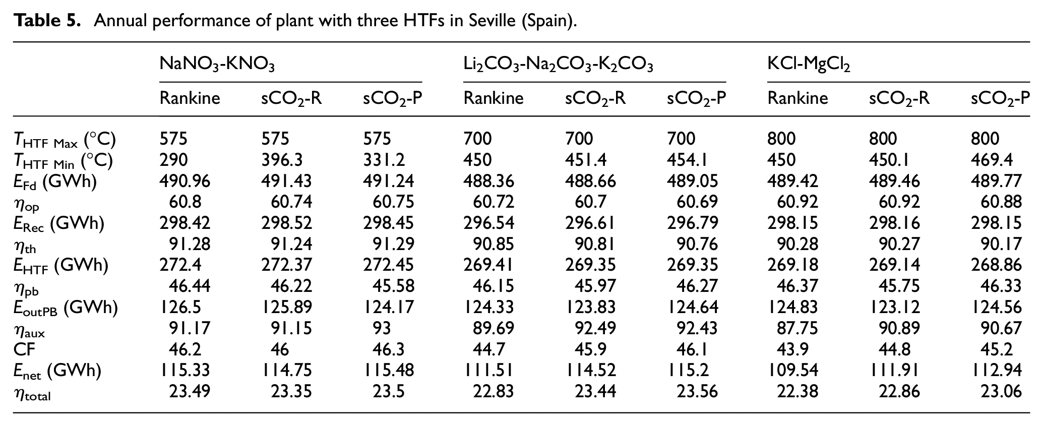
Figure 9 shows three curves of the total annual efficiency of different cycles depending on the maximum temperature of the HTF for all three HTFs considered in Dubai. One thing is common in all these charts that an increase in the HTF temperature increases the total efficiency of the plant with one exception in KCl-MgCl2 with a Partial cooling cycle whose value drops after reaching the maximum value at 800°C. In Dubai, the efficiency of the Rankine cycle has shown a similar trend to the previous location having maximum efficiency with NaNO3-KNO3 while other salts have performed less with the Rankine cycle. The Recompression cycle has shown a good efficiency at a higher temperature for both Li2CO3-Na2CO3-K2CO3 and NaNO3-KNO3 but relatively lower efficiency with KCl-MgCl2. The Partial cooling cycle has performed well as the temperature of the HTF increase. The Partial cooling cycle has shown maximum efficiency with Li2CO3-Na2CO3-K2CO3 at 700°C but NaNO3-KNO3 has surpassed it with having maximum efficiency. The efficiency of the Partial cooling cycle is low with KCl-MgCl2 but still best at 800°C, and HTF temperature lower than the maximum value.

Total efficiency of the plant as a function of HTF maximum temperature in Dubai (UAE).
Plant in Dubai with NaNO3-KNO3 as HTF performed well for all three cycles with Recompression, Rankine and Partial cooling cycle having efficiencies in incremental order having values 24.1, 24.2 and 24.33, respectively. The main contributor to this effect is higher thermal efficiency for all the cycles. Partial cooling is leading due to higher auxiliary efficiency in all of these cycles even operating at lower max HTF temperature. Plant in Dubai with Li2CO3-Na2CO3-K2CO3 as HTF has shown good performance with Recompression and Partial cooling cycle at 700°C with efficiencies close to 24.2% and 24.27%, respectively. This is due to higher power block efficiencies in both cases due to higher HTF max temperature values and higher auxiliary efficiencies. The efficiency of the Partial cooling cycle with Li2CO3-Na2CO3-K2CO3 is nearly the same as for NaNO3-KNO3. Li2CO3-Na2CO3-K2CO3 based plant has shown poor performance with the Rankine cycle and shown a low-efficiency value of 23.64% mainly due to poor auxiliary efficiency. The performance of the plant in Dubai with KCl-MgCl2 as HTF was lowest in Dubai, a similar trend to Seville for all three cycles with values of 23.83%, 23.78% and 23.32% for Partial cooling, Recompression and Rankine Cycle. This is mainly due to the lower thermal efficiency of the receiver as it is operating at a high temperature of 800°C. Also, lower auxiliary efficiency contributed to it for KCl-MgCl2 as HTF. The capacity factor is high for NaNO3-KNO3 for all cycles and Li2CO3-Na2CO3-K2CO3 with a Partial cooling cycle having a value above 66. Partial cooling with NaNO3-KNO3 achieved the highest value of 67. Net Annual energy values are also having the same trend with an enormous value of 167.28 GW for Partial cooling with NaNO3-KNO3 enlisted in Table 6.
Annual performance of plant with three HTFs in Dubai (UAE).

Considering the soiling of the heliostat mirrors and availability of the heliostats into account will reduce the overall efficiency of the plant. It will not change the trends and all HTFs and cycle results are the same but with reduced values. Table 7 enlists the efficiency values for the Seville plant for all three HTFs and it can be seen that maximum efficiency is shown by the Partial cooling cycle for both NaNO3-KNO3 and Li2CO3-Na2CO3-K2CO3 as HTF having value 20.14%.
Annual performance of plant with three HTFs in Seville (Spain) considering soiling.

Table 8 enlists the efficiency values for the Dubai plant for all three HTFs considering soiling and it can be seen that maximum efficiency is shown by the Partial cooling cycle for both NaNO3-KNO3 and Li2CO3-Na2CO3-K2CO3 as HTF having the value of 21.1% and 21%, respectively.
Annual performance of plant with three HTFs in Dubai (UAE) considering soiling.

Effect of optimization on Annual Energy for the optimized receiver in Dubai (UAE)
To increase the annual energy of the plant in Dubai, optimization is carried out. The layout is optimized along with a reduction in the diameter, the height of the receiver and height of the tower is also varied with the new field layout. The optimization of the plant in Dubai is carried out to get maximum output from the plant. Details of optimized layout and receiver are enlisted in Table 2 and the flux map of the optimized receiver is shown in Figure 10.

Map of incident Flux on the optimized receiver on the 20th March at 12:00 h in Dubai.
Figure 11 shows three curves of the total annual efficiency of different cycles depending on the maximum temperature of the HTF for all three HTF considered in Dubai for the optimized plant. The same trend persists that an increase in the HTF temperature increases the total efficiency of the plant but the total efficiency values are less than non-optimized plant values mainly due to a reduction in the optical efficiency of the optimized plant as having a larger reflective field and reduced receiver. For an optimized layout in Dubai, the efficiency of the Rankine cycle is maximum with NaNO3-KNO3 same as noted previously while other salts have not performed well with the Rankine cycle. The Recompression cycle and Partial cooling cycle have also shown similar trends with higher efficiencies at a higher temperature for all three salts. The Partial cooling cycle has shown maximum values for all three salts.
The total efficiency of the plant as a function of HTF maximum temperature for the optimized plant in Dubai (UAE).
Optimized plant in Dubai with NaNO3-KNO3 as HTF performed well with both Rankine and Partial cooling cycle at 575°C having efficiency 23.74% and 23.85%. But for Recompression, its value is a little low, that is, 23.64% due to lower auxiliary efficiency. Optimized plant in Dubai with Li2CO3-Na2CO3-K2CO3 as HTF has shown good performance with Recompression and Partial cooling cycle at higher temperatures of 700°C with efficiencies close to 23.88% and 23.95% respectively due to higher power block and auxiliary efficiencies. The Partial cooling cycle with Li2CO3-Na2CO3-K2CO3 as HTF based receiver has shown maximum values again similar to the previous non-optimize analysis in Dubai. The optimized plant in Dubai with KCl-MgCl2 as HTF has shown again lower performance for all three cycles with values 23.12%, 23.42% and 23.5% for Rankine, Recompression and Partial cooling cycle respectively. Lower thermal and auxiliary efficiencies are responsible for this behaviour. One of the notable factors in the optimized layout field plant in Dubai is very high capacity factor values such that over 77 as well as high Net annual energy values close to 193GW. NaNO3-KNO3 and Li2CO3-Na2CO3-K2CO3 with the Partial cooling cycle have maximum values with a capacity factor of around 77.5 as enlisted in Table 9.
Annual performance of plant with three HTFs for the optimized receiver in Dubai (UAE).

Table 10 enlists the efficiency values for the optimized Dubai plant for all three HTFs considering soiling and it can be seen that maximum efficiency is shown by the Partial cooling cycle for Li2CO3-Na2CO3-K2CO3 as HTF having value 20.36%.
Annual performance of plant with three HTFs for the optimized receiver in Dubai (UAE) considering soiling.

Conclusion
Concentrated solar technology has huge potential to meet the energy needs of the future and overcome climate challenges. Among concentrated solar technologies, the solar thermal tower power plant is an important and emerging field. In this study three different molten salts, that is, NaNO3-KNO3, KCl-MgCl2 and Li2CO3-Na2CO3-K2CO3 are considered as HTF of STTPP at two different locations for consideration of DNI variations. Three different power cycles, that is, Rankine, sCO2 Recompression and sCO2 Partial cooling cycles are considered to evaluate the efficiency of STTPP. Both KCl-MgCl2 and Li2CO3-Na2CO3-K2CO3 can withstand high temperature and therefore are better suited for cycles having higher efficiency at higher temperatures, for example, sCO2 Recompression and sCO2 Partial cooling cycles.
A detailed analysis is carried out and it is evident from the analysis that the Rankine cycle has shown better suitability with NaNO3-KNO3 but less performance for both KCl-MgCl2 and Li2CO3-Na2CO3-K2CO3. The sCO2 Recompression cycle has shown good performance for both KCl-MgCl2 and Li2CO3-Na2CO3-K2CO3 but its performance is less with NaNO3-KNO3. The sCO2 Partial cooling cycle was best among all three cycles with all three salts as HTF.
The performance of KCl-MgCl2 was poorest amongst all three HTFs at both locations. It is the HTF with the highest temperature sustainability amongst all but even at higher temperatures (800°C), its performance is low compared to the other two HTFs. That is mainly due to lower thermal and auxiliary efficiency. NaNO3-KNO3 has shown good performance for all three cycles but especially it is more suitable for the Rankine cycle at both locations. The Li2CO3-Na2CO3-K2CO3 performance was comparable to NaNO3-KNO3 but it even surpassed at some points such as at higher DNI with a higher temperature cycle.
An improvement (nearly +1%, 23.56% in Seville – sCO2-P – Li2CO3-Na2CO3-K2CO3, 24.33% in Dubai – sCO2-P – NaNO3-KNO3) is observed in the maximum total efficiency of the plant in Dubai compared to the same plant in Seville. This is mainly due to higher optical efficiency (nearly +2% from 60.69% to 62.3%) in Dubai of the same layout as of Seville. Higher DNI also improved the thermal efficiency (+1.5%, from 90.76% to 92.17%) of the plant in Dubai. Moreover, an improvement in the auxiliary efficiency (nearly +1.5%, from 92.43% to 93.89%) also contributed to the increment of this total efficiency in Dubai. An immense improvement is evident in the Capacity Factor (nearly +21, from 46.1 in Seville to 67 in Dubai) and net output electricity (nearly +52GW, from 115.2 GW in Seville to 167.28 GW in Dubai) of the same plant in Dubai compared to in Seville.
Optimization of the heliostat field layout, receiver and tower of the plant in Dubai has shown a reduction in overall total annual efficiency (nearly −0.38%, from 24.33% in Dubai- non-optimize receiver – sCO2-P – NaNO3-KNO3 to 23.95% in Dubai- optimize receiver – sCO2-P – Li2CO3-Na2CO3-K2CO3) of the plant. Reduction in the optical efficiency (nearly −2%, from 62.3% to 60.22%) and an increment in thermal efficiency (nearly +0.5% from 92.17% to 92.64%) is observed in the optimized Dubai plant as a result of higher concentrations, reduction in the size of the receiver and enlarged heliostat field. This enlargement of the heliostat field has increased Capacity Factor (nearly +10, from 67 in the non-optimized Dubai plant to 77.3 in the optimized Dubai plant) and net output electricity (nearly +26 GW, from 167.28 GW in the non-optimized Dubai plant to 193 GW in the optimized Dubai plant) of the plant.
Thus it is concluded that an optimized receiver plant in Dubai with Li2CO3-Na2CO3-K2CO3 as HTF and sCO2-Partial cooling as a power cycle will be the best choice at a given location (Dubai-UAE) with higher DNI conditions. Future work will be carried out with the application of other power cycles like the RMCI cycle to access further improvements if possible. Moreover, an economic analysis will be carried out to calculate the effect of these improvements on the cost of a solar thermal tower power plant in Dubai.
Footnotes
Appendix
Handling Editor: James Baldwin
Declaration of conflicting interests
The author(s) declared no potential conflicts of interest with respect to the research, authorship, and/or publication of this article.
Funding
The author(s) received no financial support for the research, authorship, and/or publication of this article.