
Abstract
In this paper, the Johnson-Cook constitutive model is modified by considering the influence of hard point such as TiC and NbC in the matrix of Inconel718 on the deformation stress. The theoretical model of cutting specific energy in the main deformation zone of Inconel718 is modified based on the new constitutive model by combining the strain gradient theory. The effect of different cutting parameters on cutting specific energy is studied, and the effect of cutting specific energy on cutting deformation and the resulting dimensional effect are also analyzed. The research results show that cutting specific energy increases with the increase of cutting speed. With the increase of cutting thickness, the cutting specific energy reduced, and the trend is non-linear. The change of undeformed chip thickness will cause size effect. The cutting specific energy increases with the reduction of the thickness of undeformed chip, and the impact of the thickness of undeformed chip on the cutting specific energy becomes smaller and smaller as the speed increases. The existence of hard points makes the main deformation zone generate a large amount of heat energy and deformation energy, which leads to dimensional effects and makes the material be more prone to adiabatic shear instability, then leads to the increase of cutting specific energy. With the increase of cutting specific energy, the width of adiabatic shear band is narrowed, the degree of serration is aggravated, and the chip morphology is closer to the experimental results.
Introduction
Inconel718 has good thermal stability and thermal fatigue properties, so it has a wide range of applications such as aerospace and nuclear energy, etc. However, poor machinability exists in the machining process due to the high temperature, plastic deformation and other problems. It is a typical kind of difficult-to-machine material. The inhomogeneity of the material itself will cause dimensional effects that will affect the cutting specific energy and thus the cutting quality.
The cutting specific energy is the energy consumed when the material per unit volume is removed, and it is an important parameter directly related to chip formation, cutting force and machining surface integrity. Özel and Ulutan 1 conducted orthogonal cutting experiments on nickel-based alloy with diamond tools at different speeds and different forward rake angles. The research results showed that the machining parameters had a great influence on the specific energy in the cutting process. Under the high-speed cutting, the thermal softening effect occurred in material reduced the cutting specific energy, and the increase of the rake angle increased the cutting specific energy. Astakhow and Shvets 2 investigated the effect of cutting parameters on cutting specific energy by machining different metallic materials at conventional speeds. The results showed that at regular speed machining, the chip undergoes uniform deformation as the cutting speed increases, and the chip compression ratio decreases, resulting in a decrease in cutting specific energy.
The FEM is usually used to build a micro-scale cutting model to visualize the plastic deformation behavior of the material, and to investigate the connection between cutting specific energy and plastic deformation behavior by post-processing the data. Uhlmann et al. 3 established a finite element model of Inconel718 and performed analytical calculations based on the conventional Johnson-Cook constitutive model to investigate the effect of cutting speed on chip morphology. Yao et al. 4 developed an energy consumption model to analyze the relationship between specific shear energy and chip morphology. Zhang et al. 5 quantified the energy consumed by the removed part of the material, derived the specific energy formula, and analyzed the influence of cutting parameters on the specific energy. Li et al.6,7 used molecular dynamics to simulate the plastic deformation behavior of materials in nanoscale cutting, and the research results of the above scholars provide a basis for the subsequent investigation of the relationship between energy and plastic behavior.
Shi et al. 8 used acoustic emission signals and finite element simulation methods for chip analysis to determine the minimum undeformed chip thickness of Inconel718, which facilitated the determination of cutting parameters. Ohbuchi and Obikawa 9 established a thermo-elastic finite element model and learned that the chip morphology is influenced by the undeformed chip thickness and cutting speed by calculation. In 2003, Aifantis 10 modified the classical plastic constitutive model to analyze the scale effect of metals. Wu and Liu 11 introduced a new flow stress equation based on strain gradient theory to describe the size effect phenomenon. Hao et al. 12 set two reinforcing phase sizes and analyzed the size effect caused by the size of the reinforcing phase based on strain gradient theory.
In this paper, considering the interphase hard points such as TiC and NbC in the matrix of Inconel718, the constitutive model is improved by combining the strain gradient theory, and then the cutting specific energy model of Inconel718 is modified. The effects of different cutting parameters on the cutting specific energy and the plastic deformation behavior of the material caused by the change of cutting specific energy are analyzed by simulation and experiment.
Experiment
Machine tool: CA6140 lathe, which can realize stepless speed regulation.
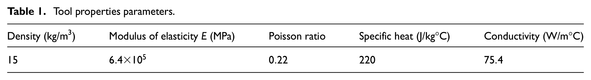
Tool: YG8 carbide tool, tool properties parameters are shown in Table 1.
Explosive rapid tool drop experiment was carried out to obtain chip roots, and the morphology of chip roots was observed by metallographic microscopy.
Cutting force measurement: It consists of three way dynamometer (Kistler 9257A), 5007 type charge amplifier and data acquisition card.
Compression experiments were performed using an electronic universal experimental compressor at a room temperature of 20°C and a strain rate of 0.001. At high strain rates, the Hopkinson compression bar experiment (SHPB) was carried out to obtain the material properties. The experimental equipment are shown in Figure 1.
After using aqua regia (3HCl + HNO3) to etch the section of the treated Inconel718 sample for 20 s, the super depth of field microscope was used to observe it and obtain the microstructure of the workpiece. It can be seen that the hard points are randomly distributed, as shown in Figure 2.
Tool properties parameters.
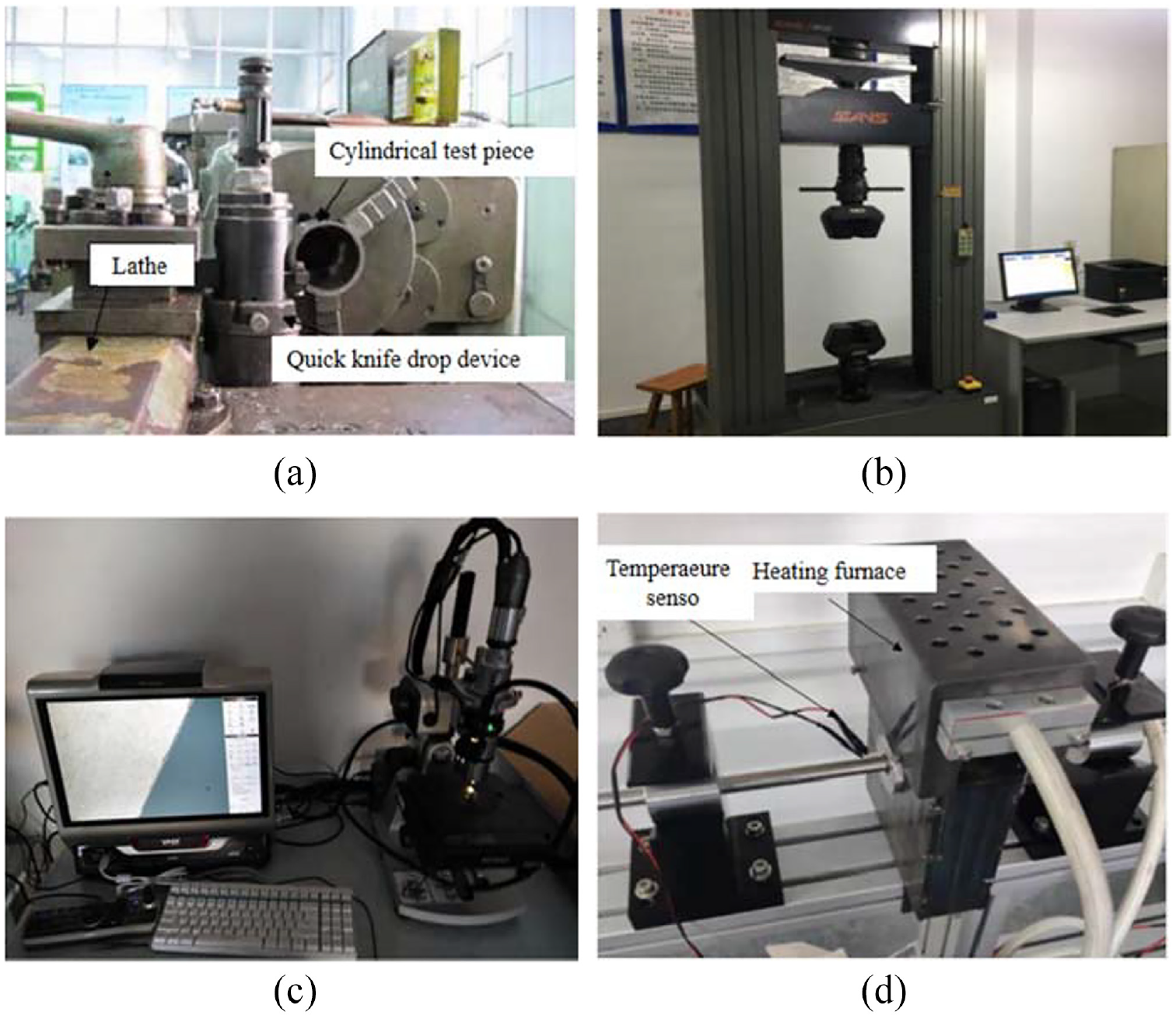
Experimental equipment (a) Explosive rapid tool drop equipment. (b) Electronic universal experimental compressor. (c) Ultra-depth micro-measuring device. (d) Heat device in the SHPB tests.
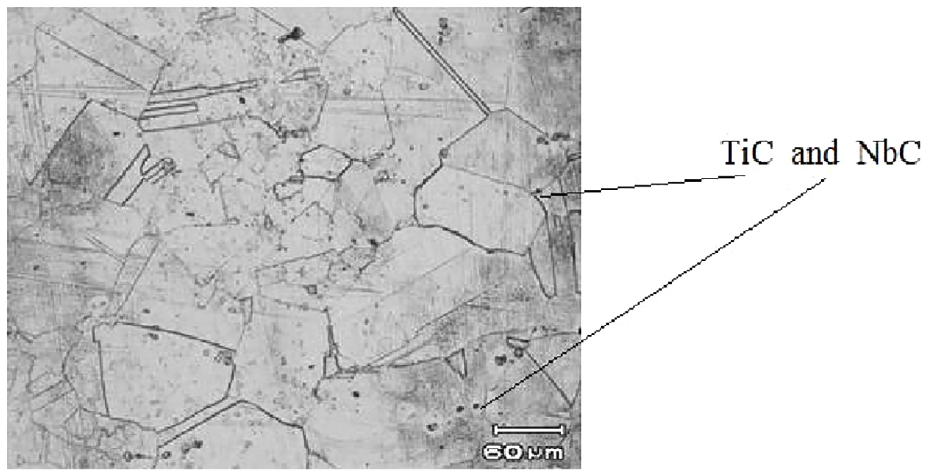
Microstructure of workpiece material.
Results and discussion
Establishment of Johnson-Cook constitutive model
When using finite elements method for simulation, it is necessary to know the relationship between temperature, stress, strain and strain rate during the cutting process. The Johnson-Cook model can reflect the connection among them well, and the constitutive model is shown in equation (1).
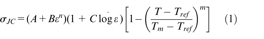
Where
The values of the above required parameters can be obtained by compression experiments and Hopkinson pressure bar experiments (SHPB), where
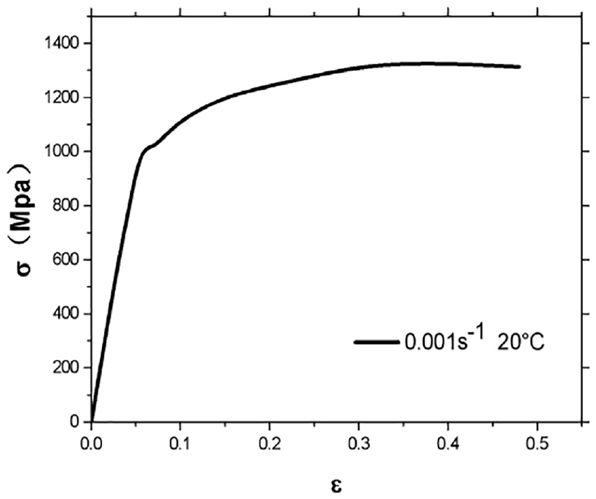
True stress-strain curve.
The softening coefficients

Stress-strain curves at different temperatures.
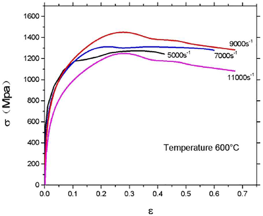
Stress-strain curves at different strain rates.
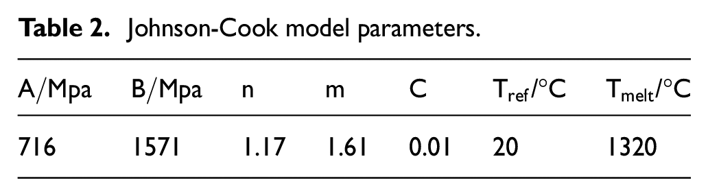
In summary, Johnson-Cook model parameters can be obtained, as shown in Table 2
Johnson-Cook model parameters.
Improvement of the constructive model
When the cutting process is analyzed under microscopic conditions, the classical constructive model has some limitations and does not consider the effect of hard points on flow stresses and dislocation slip when high-speed cutting is performed. The size effects caused by changes in cutting thickness and undeformed chip thickness during the cutting process cannot be explained in detail using conventional constructive models. The Johnson-Cook constructive model needs to be revised for the above two reasons.
Interphase hard points such as TiC and NbC exist in the matrix of nickel-based superalloy Inconel718. During high-speed cutting, the hard points has an important influence on the plastic deformation behavior and microstructure change of the material at high temperature and high strain rate. When stress is applied, it affects the movement of dislocation lines, thus changing the yield stress and the rate of work hardening. Hard points also affects the movement of grain boundaries, thus affecting the dynamic recovery process. Since hard points cannot be cut off in cutting process, the dislocation line bends when it encounters a hard point, thus creating a dislocation loop as shown in Figure 6.
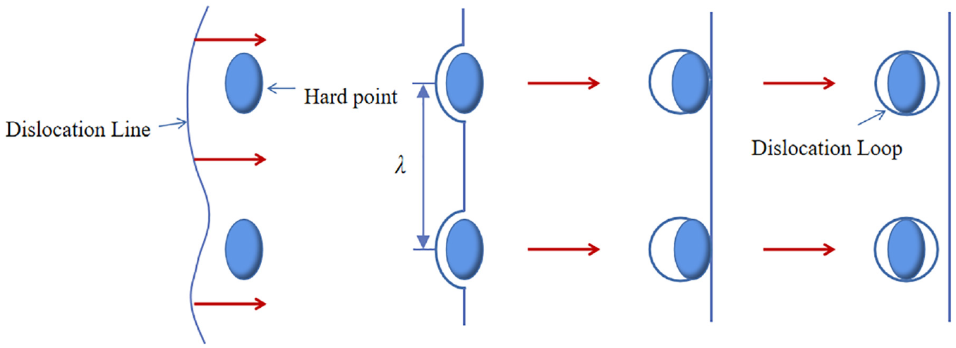
Schematic diagram of the dislocation line around a hard point.
In the process of plastic deformation, due to the linear tension of the dislocation, a dislocation loop is gradually formed near the hard point. The dislocation line tension can be expressed as 13 :

Where
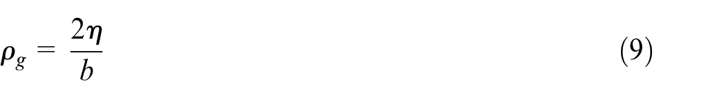
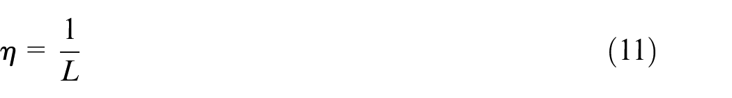
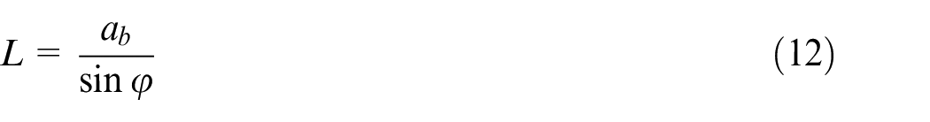
The distance between adjacent hard points is
The relationship between flow stress and tangential stress is known to be:

In conclusion, the constructive model can be rewritten as when considering the hard points:
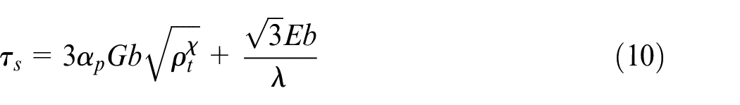
The literature 14 proposed a Taylor-based theory of nonlocal plasticity to explain the size dependence of plastic deformation on micron and submicron length scales. In the theory of nonlocal plasticity, the geometrically necessary dislocation is expressed as a nonlocal integral of the strain field. To estimate the deformation resistance of a material containing hard points, the expression for the flow shear stress is obtained using Taylor’s relation as:
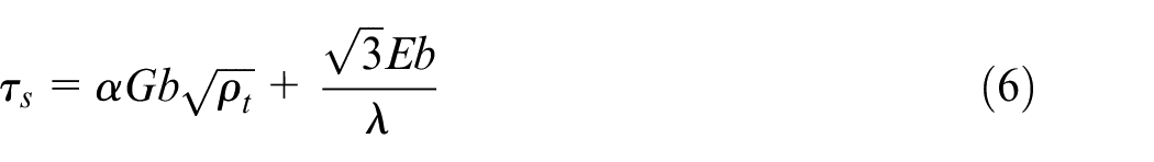
Where
The total dislocations

Where
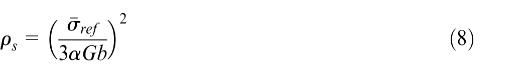
The statistical storage dislocation is generated by a uniform strain. Nix and Gao 15 proposed to express it without considering the strain gradient as:
The geometrically necessary dislocations is related to the strain gradient, and the relationship between them is:
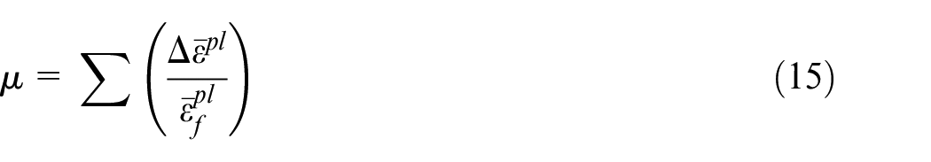
In order to make the calculation of shear flow stress in the constructive model more accurate, a correction coefficient is introduced.
Where
Joshi and Melkote 16 modeled the deformation zone or strain field using the strain gradient plastic deformation theory. The PDZ configuration was analogized with the single crystal dislocation model to calculate the unit displacement and length of the shear deformation zone, and the strain gradient was derived as follows:
Where
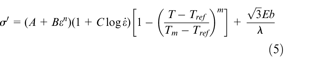
Thus, the final modified constructive model is expressed as:
Where the Burgers constant
Finite element modeling in cutting process
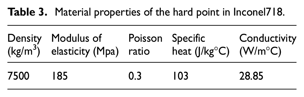
Due to the presence of hard points, the strain hardening process is mainly controlled by the geometrically necessary dislocation density evolution, and the model considering the strain gradient effect has a smaller peak plastic strain and higher dislocation density values. Therefore, the strain gradient theory-based modified constructive model is applied to establish the cutting model containing hard points. The hard points contained in Inconel718 are set to the size of 2
Material properties of the hard point in Inconel718.
A two-dimensional cutting finite element model is established using Abaqus, and a single-precision offset setting method is applied to set the mesh density in order to save computational effort. The cutting tool is set as a rigid body, and the tool mesh is divided by a CPE3T cell. In order to avoid non-convergence in the case of excessive stress, the tool tip is set as a circular arc, refining the tool tip mesh and limiting the degrees of freedom in the Y-direction. The CPE4RT cell is used for workpiece meshing, which is only set at the damage layer when setting the failure displacement, so the mesh density of the part where the workpiece and tool are in contact is relatively dense. Secondary development using python language to insert hard points and write strain gradient program using FORTRAN language. Based on the above theory, a finite element simulation model containing hard points combined with strain gradient theory is established as shown in Figure 7.
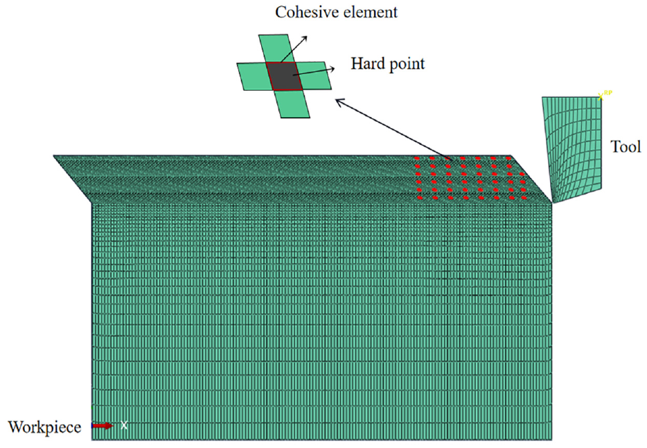
Finite element simulation model.
The criterion used in the finite element simulation is the JC-damage criterion, and the critical value of the plastic strain is calculated based on this failure criterion.
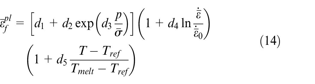
Where
Whether failure occurs depends on the value of
Modeling and analysis of cutting specific energy
Based on the strain gradient plastic deformation theory for high-speed cutting of nickel-based alloys containing hard points, the schematic diagram of a sawtooth chip formation is shown in Figure 8. In this model, there are two adiabatic shear bands separating each sawtooth, and the spacing of the chip and the width of the adiabatic shear band are important influencing factors for the shear strain generated in the shear band.
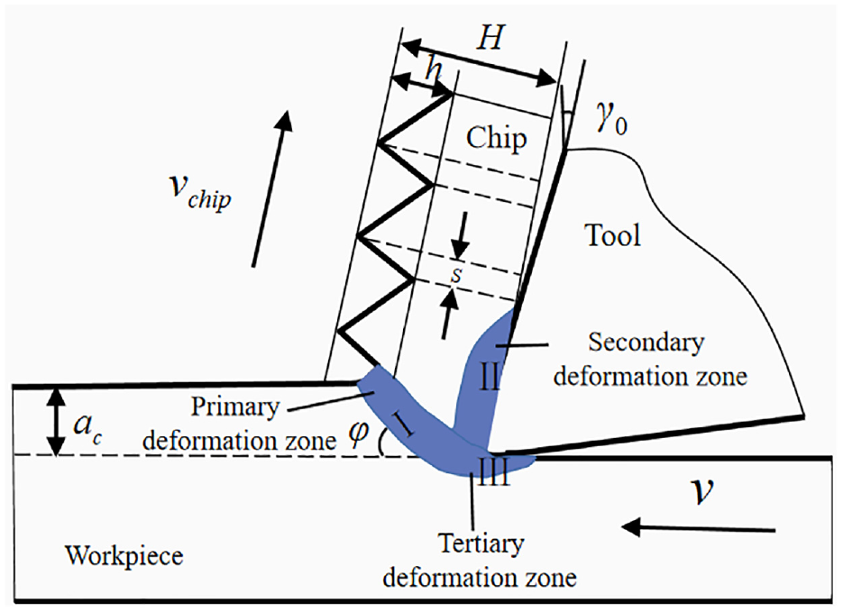
Schematic diagram of serrated chips.
In order to make the cutting specific energy more accurate, this paper adopts the equivalent chip thickness. The shaded areas I, II, and III indicate the primary deformation zone, the secondary deformation zone, and the tertiary deformation zone, respectively. The primary deformation zone is mainly plastic deformation energy, and its deformation is characterized by shear slip of the cutting layer. The secondary deformation zone is mainly the friction energy between the tool-chip contact surface. The tertiary deformation zone is the area where the machined surface layer near the cutting edge is deformed by the extrusion and friction of tool flank face, and the deformation energy in this area is assumed to be negligible due to the small energy.
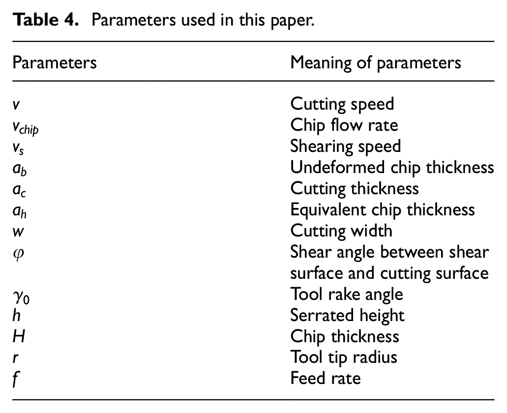
The energy consumption in cutting process can be approximated as the sum of the plastic deformation energy consumption in the primary deformation zone and the frictional energy consumption in the secondary deformation zone, where the plastic deformation energy consumption mainly originates from the primary shear zone. This paper focuses on the cutting specific energy of plastic deformation in the main deformation zone. The properties of each parameter are shown in Table 4 below. In order to study the cutting specific energy under different cutting parameters, the range of cutting speed is set at 60–120 m/min and the rake angle is set at 6°.
Parameters used in this paper.
Establishing theoretical model of cutting specific energy
In high-speed cutting, the formation of serrated chips is due to local deformation mainly concentrated within the adiabatic shear zone. Shaw 18 proposed that the energy required to make the material deform in the main deformation zone is:
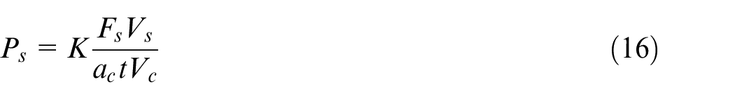
Where
In the cutting model with hard points, the stress increases when bypassing the hard points and the shear force changes as a result, and the cutting specific energy changes. Assuming that it consists of two parts, one is the shear force due to shear and the other is the increased shear stress due to the presence of hard points, it follows that:

Considering the case of hard points, the theoretical shear strain based on strain gradient theory is:
Where
The adiabatic shear band width is an important parameter in equation (18). When cutting starts after a certain stress is applied, local shear slip will occur at the boundary, and the chip flow speed is less than the cutting speed, so local shear deformation will occur and an adiabatic shear band will gradually form. According to the paper written by Molinari et al.,
19
the adiabatic shear band width based on strain gradient theory
Where
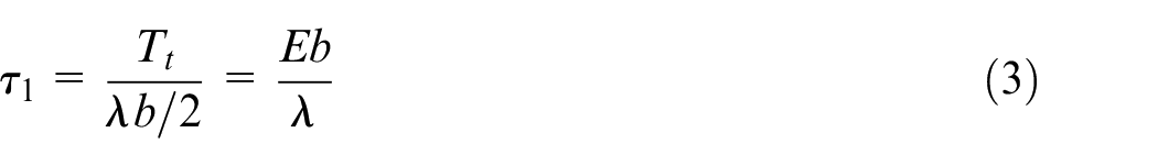
Equivalent chip thickness
The shear angle
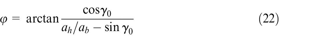
Figure 9 illustrates the velocity relationship and undeformed chip thickness. According to Figure 9, the shear rate
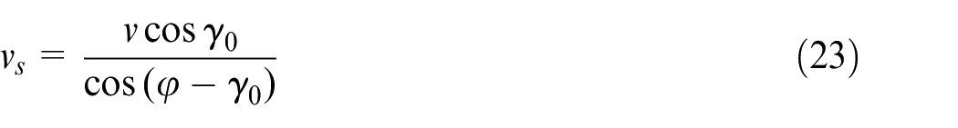
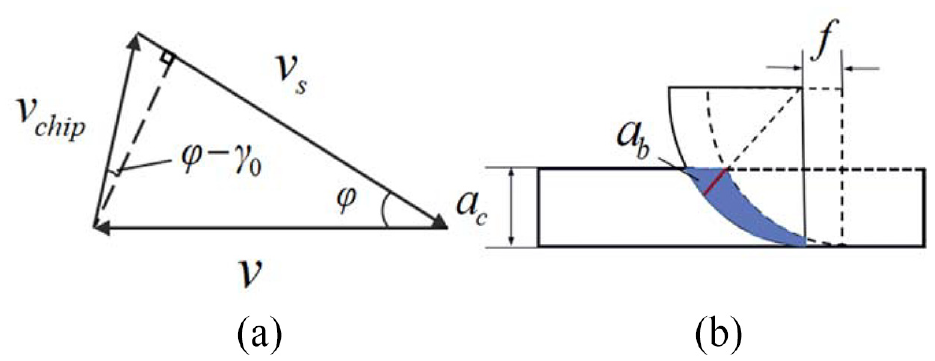
Velocity relationship and undeformed chip thickness (a) Schematic diagram of Velocity relationship. (b) The undeformed chip thickness
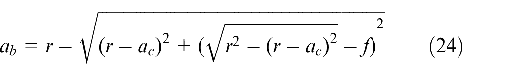
In this paper, the undeformed chip thickness is defined as the distance between the cutting edge and the workpiece surface to the center of the tool tip arc, as shown in Figure 9(b), which can be expressed as:
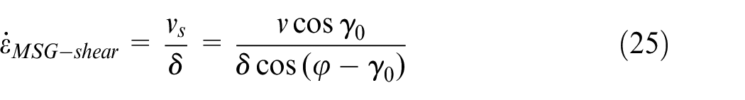
The shear strain rate of the main deformation zone is shown as equation (25).
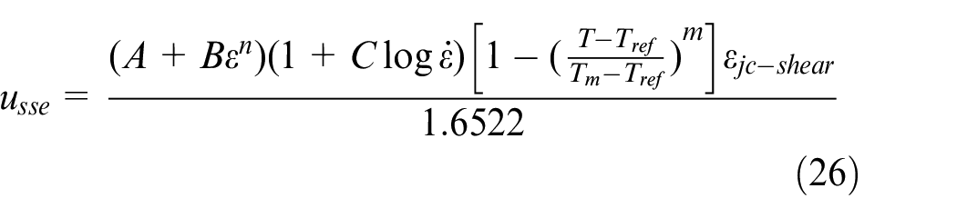
In the literature, 20 a theoretical cutting specific energy model for cutting nickel-based alloy Inconel718 was proposed using the Johnson-Cook constructive model.
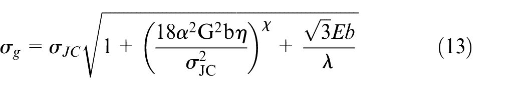
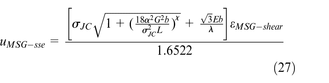
Considering the material’s own endogenous dimensions and the size effects caused by thermal softening effects, undeformed chip thickness, etc., the above modified Johnson-Cook constructive model is introduced. Combined with equations (13), (18), (25), and (26), the modified theoretical cutting specific energy model of the main deformation zone is obtained.
Effect of different parameters on cutting specific energy
Effect of cutting speed on cutting specific energy
In order to investigate the effect of cutting speed on cutting specific energy in high-speed cutting, a cutting model was established under the conditions (cutting thickness
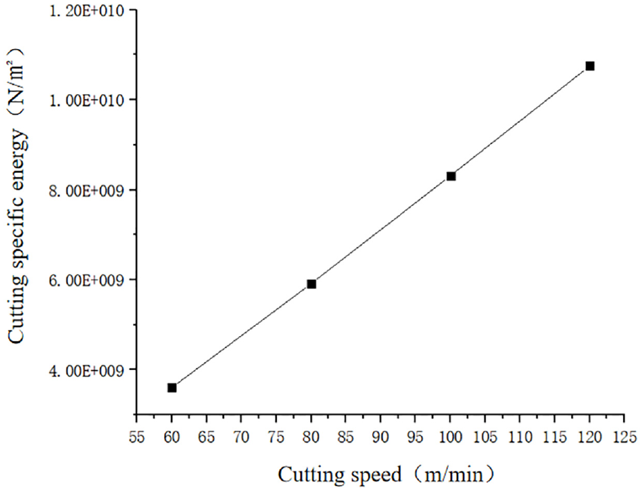
Variation of cutting specific energy with different speeds.
When the cutting speed
When plastic deformation occurs along the shear direction, the interaction between the hard points and the internal dislocations hinders the proliferation of dislocation slip, which in turn generates the stress concentration to form dislocation rings. The formation of dislocation rings led to the increase of the stress to be overcome during cutting, resulting in increased flow stress. Unlike conventional cutting, when Inconel718 with hard points is cut at high speed, a large amount of deformation energy and heat energy, which generated near the hard points in the main deformation zone due to shear deformation, caused chip instability, and then led to local adiabatic shear deformation and more severe plastic deformation.
The gradual increase in cutting speed leads to an increase of friction at tool-chip interface, and as the temperature increases with speed, the cutting specific energy increases rapidly, which in turn causes the chip to form the first full serration. Figure 11 represents the temperature cloud chart of the first full serration formed at cutting speeds of 60 and 80 m/min, respectively.
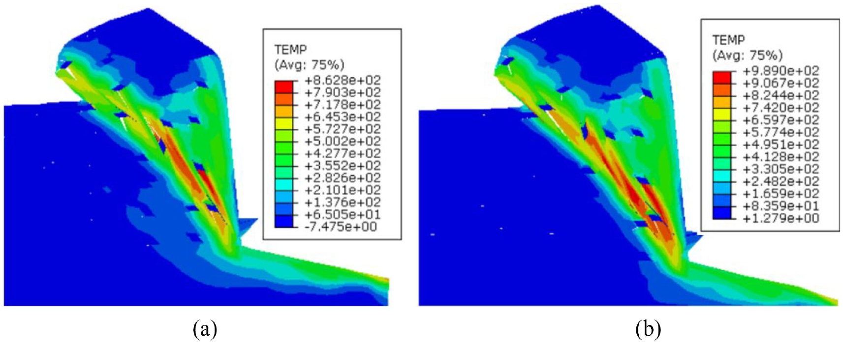
Cloud chart of the first full serration formed at different cutting speeds. (a)
The thermal softening effect during further cutting makes the cutting specific energy increase. When the cutting speed increases to 100 m/min, with the further increase of cutting speed, the flow speed of chips is greater than the speed of plastic deformation in the main deformation zone, so the shear angle increases. Thus the serrated chips gradually formed, as shown in Figure 12. The plastic deformation energy in the main deformation zone increases, and the cutting specific energy increases.
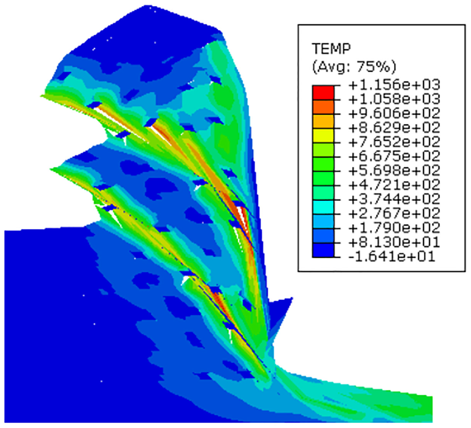
Serrated chips.
Effect of cutting thickness on cutting specific energy
When the cutting speed is 60 m/min, the cutting thickness is set as 0.041, 0.042, 0.043, 0.044, 0.045, 0.046 mm, and the main deformation zone is selected for analysis. Using the modified cutting specific energy model, the theoretical value of cutting specific energy in the plastic deformation zone at different cutting thicknesses was calculated and compared with the experimental value. The experimental value of the cutting specific energy is known to be derived by Su and Liu 21 and expressed as:
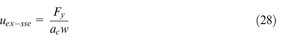
Figure 13 shows the cutting specific energy obtained by experiments and simulation at different cutting thickness. According to Figure 13, the simulated value and the experimental value tend to be gradually the same, and the cutting ratio energy increases with the decrease of cutting thickness. The trend of cutting specific energy is non-linear showing a more obvious size effect. The smaller the cutting thickness in high-speed cutting, the more obvious the size effect.
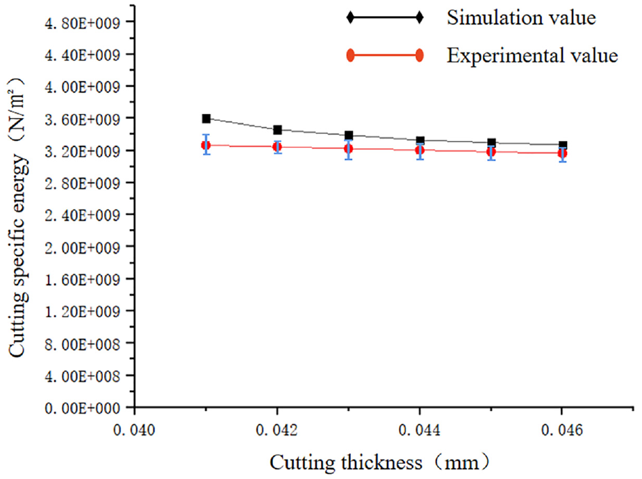
Cutting specific energy at different cutting thickness.
When the cutting thickness is 0.045 mm, the stress cloud map is obtained by finite element simulation. Figure 14(a) to (d) show the change of stress during the cutting process and the evolution of the first serration gradually formed in the removed material. When the tool starts to move forward and encounters a hard point, the presence of the hard point leads to the increase of the grain boundary, which results in dislocation plugging and impedes the advance of the tool, and the dislocation slip starts to become difficult and eventually forms a serrated chip. Because the principal stress value is related to the geometric necessarily dislocation density, with the increasing length of the shear surface, the maximum principal stress value gradually decreases. The cutting specific energy at this time increased compared with the cutting specific energy under the condition of larger cutting thickness.
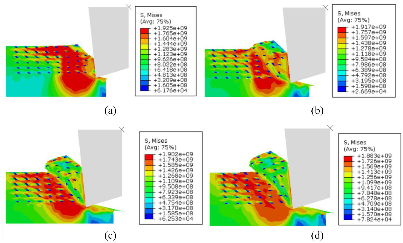
Variation of stress during the cutting process and the formation process of the first serration. (a) Initial stage of the first sawtooth formation. (b) Stage II of the first sawtooth formation. (c) Stage III of the first sawtooth formation. (d) Final formation of the first sawtooth chip.
Effect of undeformed chip thickness on cutting specific energy
According to Joshi and Melkote,
16
the shear strength of the material is inversely proportional to the length of the shear plane, and the length of the shear surface is expressed as
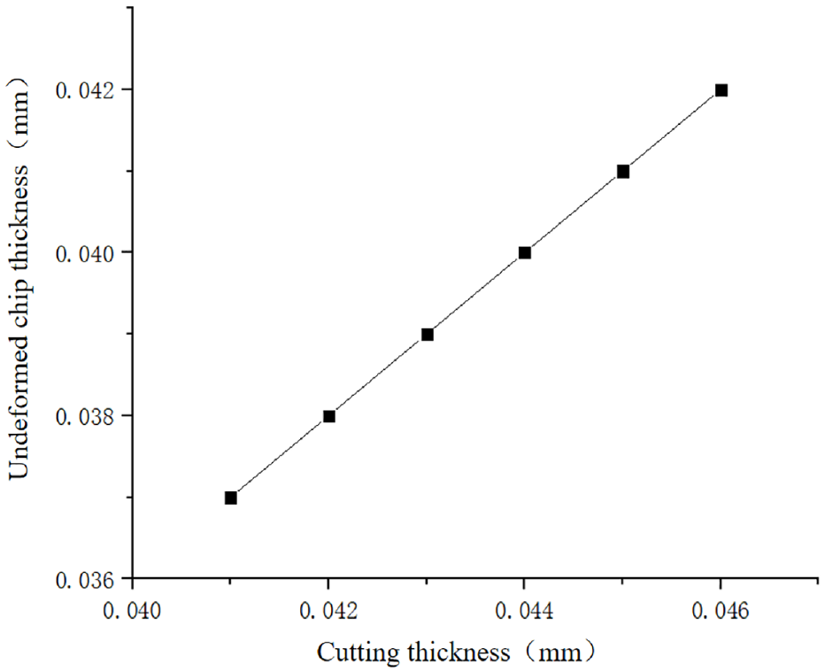
Variation of undeformed chip thickness
The four curves in Figure 16 show the change of cutting specific energy with the increase of undeformed chip thickness at different speeds, respectively. It can be seen that the cutting specific energy is inversely proportional to the thickness of the undeformed chip
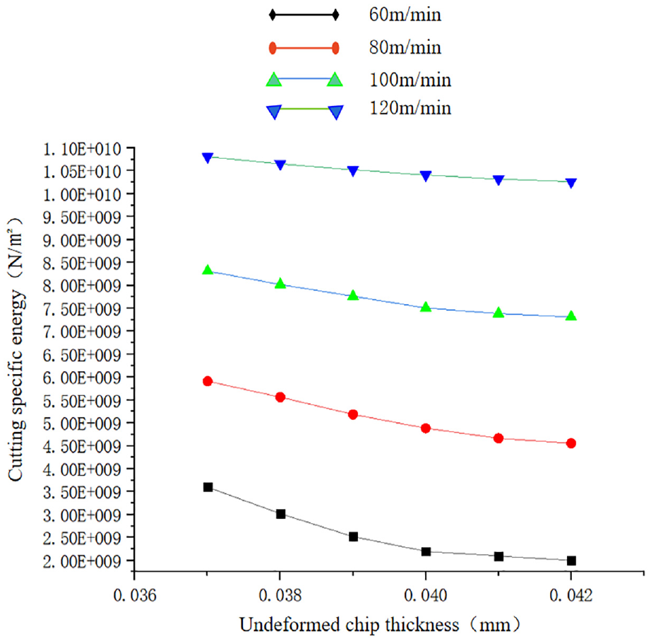
Cutting specific energy at different undeformed chip thickness.
The effect of cutting specific energy on cutting deformation
The variation of different cutting parameters causes the cutting specific energy to change, thus having an effect on the plastic deformation produced in cutting process. When the cutting speed changes, the chip morphology changes as well. Equation (25) shows that the shear strain increases when the shear band width gradually becomes narrower, and the relationship between the shear band width and cutting specific energy is shown in Figure 17. According to Figure 17, the shear band width gradually decreases as the cutting specific energy increases, which shows a more obvious size effect.
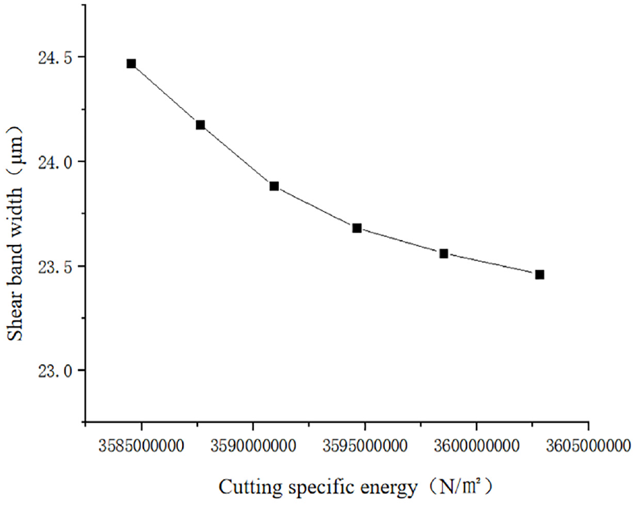
Relationship between shear band width and cutting specific energy.
In order to verify the effect of cutting specific energy on cutting deformation at different cutting speeds, the width of the adiabatic shear band at different speeds was observed by using Metallographic microscope. The width of the shear band becomes progressively narrower, and the theoretical model results are consistent with the experimental findings (see Figure 18).
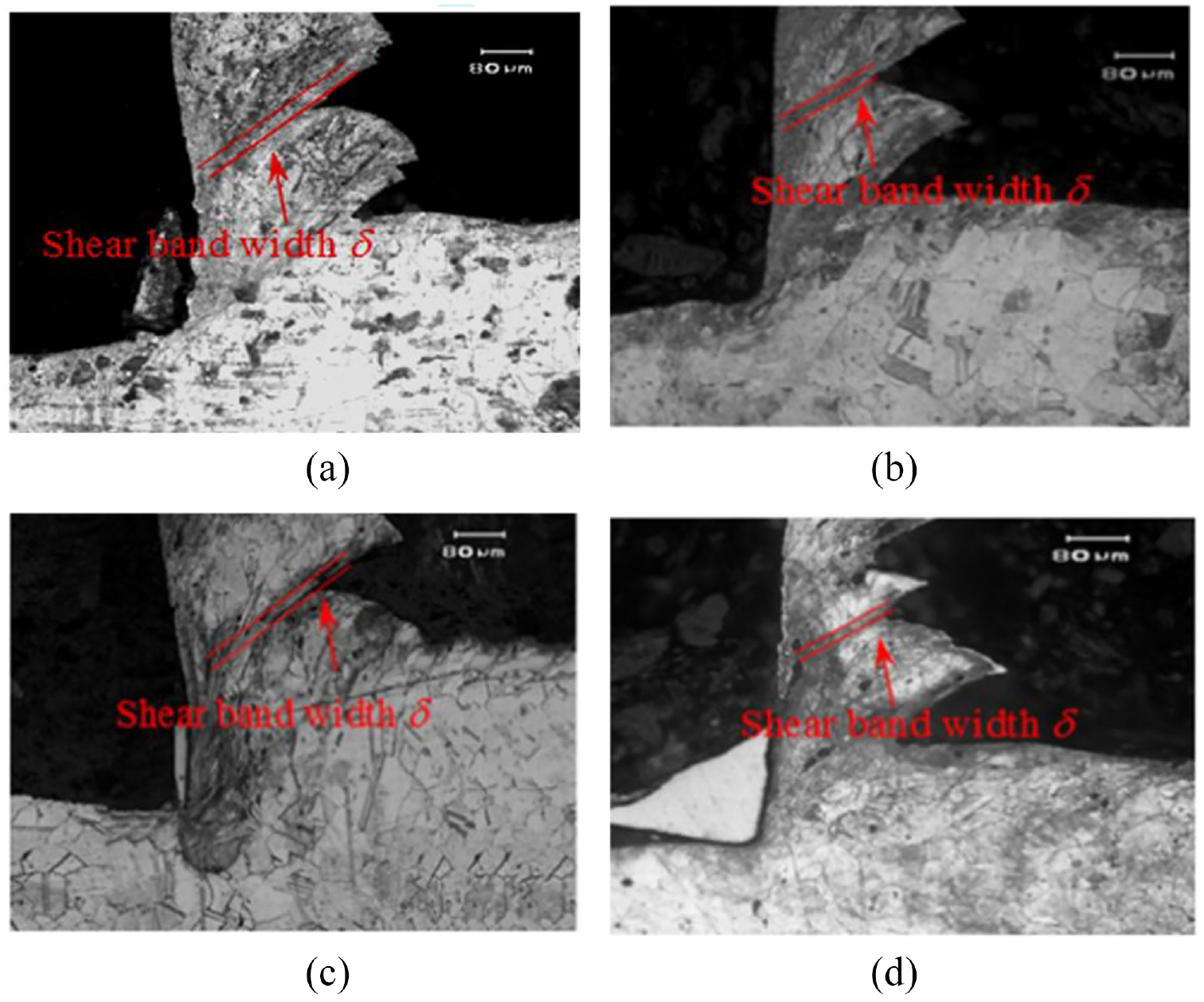
Shear band width. (a) 60 m/min, (b) 80 m/min, (c) 100 m/min, and (d) 120 m/min.
The degree of seriation at different speeds is shown in Figure 19(a). It can be seen that the degree of seriation increases with the increase of cutting speed during the cutting process. Taking the speed as the intermediate value, the relationship between the degree of seriation and the cutting specific energy can be deduced as shown in Figure 19(b). The graph shows that the degree of chip serration increases when the cutting specific energy increases. Figure 20 shows the chip shape obtained by finite element simulation and experiment at
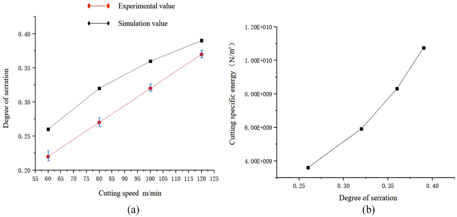
Relationship between the degree of serration and cutting specific energy. (a) Variation of degree of seriation with cutting speed and (b) variation of cutting specific energy with degree of seriation.
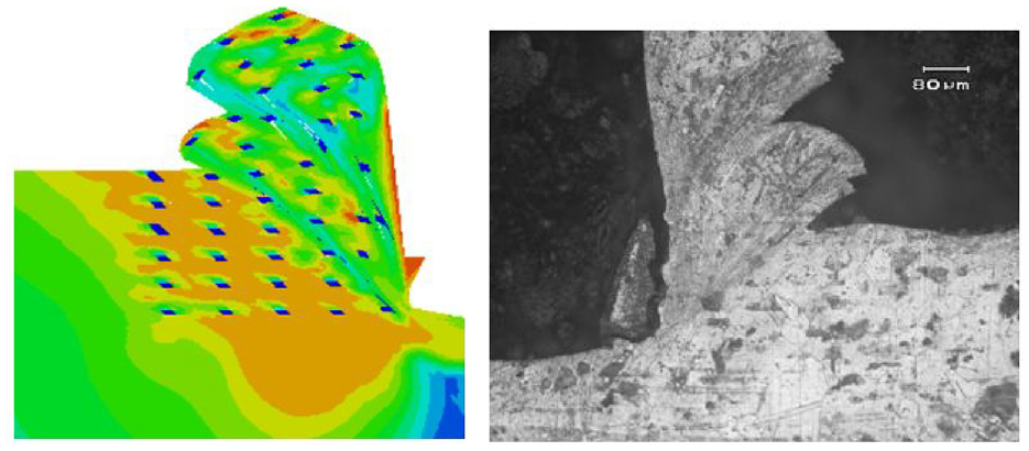
Chip shape at
When the cutting speed is greater than 80 m/min, it shows regular serrated chips. Figure 21 are the sawtooth chips obtained at
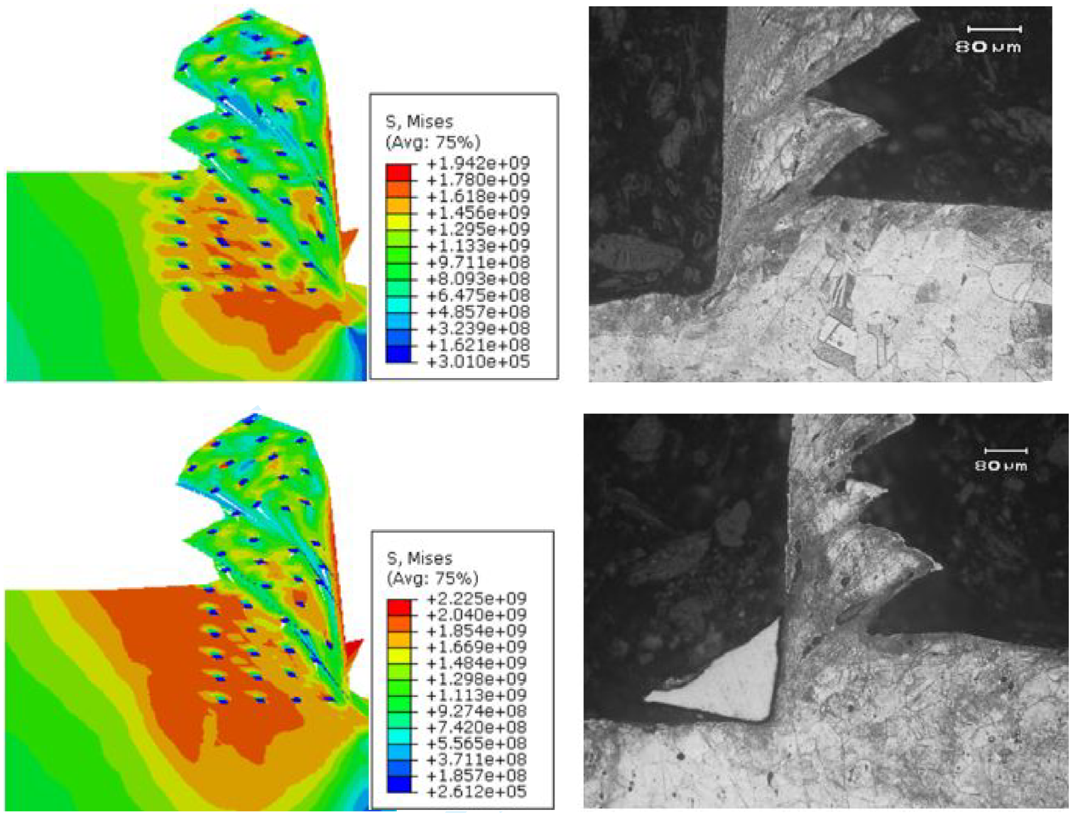
Chip morphology at 100 and 120 m/min.
At lower speeds, the cutting thickness
Conclusions
In this paper, the Johnson-Cook constitutive model is modified by considering the effect of hard point on cutting stress and combined with strain gradient theory. In order to consider the influence of size effect on cutting deformation, the improved constitutive model is introduced into the theoretical model of cutting specific energy in the process of cutting Inconel718, and the effect of different cutting parameters on cutting specific energy is calculated. The conclusions can be drawn as:
The new established Johnson-Cook constitutive model considered hard points in the material matrix and used the strain gradient theory, which can more accurately describe the physical and mechanical properties of materials. Based on the modified JC model, the cutting specific energy model is established.
Through cutting experiments and cutting simulation, the influence of different parameters on cutting specific energy is described. The cutting specific energy increases with the cutting speed, and the cutting specific energy decreases with the decrease of cutting thickness. During the formation of serrated chips, with the increase of undeformed chip thickness, the change trend of cutting specific energy decreases nonlinearly.
The mechanism of cutting deformation is revealed. Due to the existence of hard points, a large amount of heat energy and deformation energy generated in the main deformation zone during shear deformation, leading to material softening. The size effect caused by thermal softening makes the increase speed of cutting specific energy gradually slow down. When the cutting speed increases, the width of shear band decreases with the increase of cutting specific energy, and the degree of sawtooth increases with the increase of cutting specific energy.
Footnotes
Declaration of conflicting interests
The author(s) declared no potential conflicts of interest with respect to the research, authorship, and/or publication of this article.
Funding
The author(s) disclosed receipt of the following financial support for the research, authorship, and/or publication of this article: This work is supported by National Natural Science Foundation of China (52275404, Key industrial technology research project of Jilin Province (20210201043GX), Project of Science and Technology Bureau of Changchun City, Jilin Province (21ZY40).
This work is also supported by Key Laboratory for International Cooperation in High-performance Manufacturing and Testing of Jilin Province (2022 0502003GH), and Key Laboratory of Micro/Nano and Ultra-Precision Manufacturing of Jilin Province (2014 0622008JC)
Ethical approval
This article does not contain any studies with human participants or animals performed by any of the authors.