
Abstract
Serrated chip is the frequent chip morphology during high-speed machining of ductile materials, while the mechanism of serrated chip formation still remains some ambiguous aspects. This article presents the investigation of chip morphology from the viewpoint of chip free surface and cross section. Experiments of orthogonal cutting hardened AISI 1045 steel and 7050-T7451 aluminum alloy were carried out. The cutting speed of AISI 1045 steel was varied from 100 to 1000 m/min, while 7050-T7451 aluminum alloy was machined at the cutting speed of 100–2500 m/min. The feed rate per tooth was varied from 0.025 to 0.20 mm/z corresponding to each experimental cutting speed. The research shows that the microstructure of chip free surface evolves from lamellae to folds and then to dimples. According to the experimental results, a new model of serrated chip formation based on mixed mode of ductile fracture and adiabatic shear is proposed. For the “ductile fracture–adiabatic shear” serrated chips, two distinct zones of ductile fracture and dimples were observed on the slide surface of serrated segments. Through studying chip morphology evolution under different combinations of cutting speed and feed rate, it is found that the degree of chip segmentation has positive correlation with the two parameters. The concept of “critical cutting load” is then proposed to illustrate the conditions under which serrated chips may occur. And the critical cutting load of AISI 1045 steel and 7050-T7451 aluminum alloy is determined by experiments as 0.024 and 0.10 m2/(min z), respectively.
Keywords
Introduction
In recent years, high-speed machining (HSM) has been widely used as an advanced manufacturing technology in areas such as aerospace, automobile, die and mold industries and so on.1–3 HSM has advantages such as high machining efficiency, low cost, excellent surface quality, low cutting force and the ability to machine hardened materials.4–6 Based on these superiorities, HSM can be applied instead of grinding in finishing process, especially for materials with high hardness. Compared with traditional machining, HSM has several differences in aspects such as chip formation mechanism, variations of cutting force and cutting temperature, tool wear and failure mechanism and so on.7–11 Among these aspects, investigation of chip formation mechanism is particularly important, since the transformation of chip morphology in HSM does great influence on the rest ones.12–15
From the viewpoint of the cross section, there are two basic types of chip morphology known as steady-state continuous ones and cyclic ones. 16 Steady-state continuous chips involve homogeneous shear when the removed layer material flows across the primary shear zone, and this kind of chip usually occurs under the traditional cutting speed and low uncut chip thickness. Cyclic chips were referred to as the serrated chips (also called “segmented chips,”“saw-tooth chips” or “shear-localized” chips) in general, which are usually formed in the range of high cutting speed or large uncut chip thickness. Apart from serrated chips, cyclic chips also cover other morphological ones. For example, Vyas and Shaw 16 classified cyclic chips into four subcategories such as discontinuous chips, wavy chips, chips produced with a built-up edge (BUE) and saw-tooth chips. Liu and Su 17 carried out the cutting experiments with AerMet 100 steel in a wide-range cutting speed (from 30 to 7000 m/min), and the conclusion was drawn that cyclic chips evolving from segmentation to fragmentation depending on material dynamic properties. Nevertheless, as for frequently used metals in industrial manufacture, the cyclic chips generated in HSM are serrated. On one hand, the occurrence of serrated chips is desirable from the viewpoint of chip disposal, which contributes to the automatic machining. On the other hand, their emergence may lead to vibration of cutting force, which can result in rapid tool wear and poor surface finish.7,18,19 In consideration of the aforementioned wide application of HSM and the important role of chip formation, researches on serrated chip formation mechanism under different cutting conditions turn out to be significant for the deeper insight of whole cutting process. Furthermore, it can also provide theoretical instructions for optimization of machining parameters in industrial production.
Currently, there are mainly two different theories to explain the serrated chip formation. One is adiabatic shear theory, which suggests that the serrated chips are caused by the periodic thermoplastic shear instability happening within the primary shear zone. It presents that the shear instability occurs when the rate of thermal softening exceeds the rate of strain and strain rate hardening. Due to the shear process takes place in very short time, the heat generated by severe plastic deformation in primary shear zone is unable to dissipate. Sometimes, adiabatic shear is also called as “localized shear,”“catastrophic shear” and “thermoplastic instability shear.” Representative researchers who support the adiabatic shear theory mainly include Recht, 20 Komanduri et al., 21 Davies et al., 18 Semiatin and Rao, 7 Molinari et al., 9 Sutter 22 and Joshi et al. 23 Their experiments showed that a narrow adiabatic shear band was observed extending along the primary shear zone from the perspective of chip cross section. Another theory to explain the serrated chip formation is periodical crack theory, which proposes that the serrated chips result from cracks initiating periodically from the free surface of the chip and then propagating to the tool tip. The periodic cracks weaken the primary shear zone leading to catastrophic shear. Representative researchers who hold this view mainly include Nakayama et al., 24 Shaw and Vyas, 25 Elbestawi et al. 26 and Poulachon and Moisan. 27 Essentially, the point of divergence between these two theories lies in whether the slide surface of serrated segment is caused by adiabatic shear or not. With the improvement of chip formation mechanism, a consensus has been gradually reached that serrated chip formation is prone to be originated from adiabatic shear for ductile materials, while it is more inclined to be induced by periodic cracks for brittle materials.28,29 However, more comprehensive and systematic investigations about serrated chip formation including analytical and experimental explorations should still be conducted in order to break the gap between the present knowledge and objective facts.
The aim of this article is to present the morphology of serrated chips obtained under different cutting parameters and to study the transition from continuous to serrated chips in terms of critical cutting load. Unlike traditional research techniques, this article resorts to studying the microstructure morphology of free surface of serrated chips, and some interesting experimental results are achieved that can be used to reveal the mechanism of serrated chip formation deeply. Based on this, the mechanism of serrated chip formation based on the mixed mode of ductile fracture and adiabatic shear is proposed. In addition, the degree of chip segmentation is investigated under different combinations of cutting speed and feed rate.
Experiments
Two workpiece materials including hardened AISI 1045 steel and 7050-T7451 aluminum alloy are used in this study. Both of them are widely employed in industrial manufacture owing to their excellent mechanical properties. Especially, for 7050-T7451 aluminum alloy, it has extensive application in vital areas such as aerospace, automobile, shipbuilding and so on. Generally, workpiece materials with low hardness and high thermo-physical properties (the multiplication of thermal conductivity, density and specific heat) are apt to produce continuous chips in a wide range of cutting speed. These materials mainly include aluminum alloy, mild steel, unhardened steel, alloy steel and so on. On the contrary, those materials with high hardness and low thermo-physical properties tend to produce serrated chips under relatively lower cutting speed. Those materials mainly contain hardened steel, hardened alloy steel, titanium alloy in addition to superalloy and so on. 7050-T7451 aluminum alloy and hardened AISI 1045 steel belong to the above two kinds of materials, respectively, so the investigation on chip formation mechanism of these two materials has great representative significance. And this is the important reason for choosing the two materials as research object.
AISI 1045 steel used in the experiments has been heat treated, and its hardness is about 43–45 HRC, while 7050-T7451 aluminum alloy is in original state as delivered. The chemical compositions of AISI 1045 steel and 7050-T7451 aluminum alloy are listed in Tables 1 and 2 separately.
Chemical compositions of AISI 1045 steel.
Chemical compositions of 7050-T7451 aluminum alloy.
The cutting experiments were conducted on DAEWOO ACE-V500 vertical machining center whose spindle rotational speed is 80–10,000 r/min. A 90°SN slot milling cutter whose type is Kennametal 4.96164-210 was used. The tools applied are coated carbide inserts (KC725M), and the tool type is SNHX12L5PZTNGP. According to different physical and mechanical properties, AISI 1045 steel was machined at the cutting speeds of 100–1000 m/min, while 7050-T7451 aluminum alloy was machined at the cutting speeds of 100–2500 m/min. The feed rate per tooth was varied from 0.025 to 0.20 mm/z corresponding to every cutting speed. The feed rate per tooth corresponds to the uncut chip thickness in orthogonal cutting. After each cutting was finished, the insert was exchanged by a new one for the sake of eliminating the effect of tool wear on experimental results.
Chips at different cutting parameters were collected after machining. Then, the free surface microstructure of different morphology chips was observed and photographed with the aid of scanning electron microscope (SEM). After this, the chips were inlaid into mosaic materials as specimens, which were followed by the procedure of grinding and polishing. Then the cross sections of chips were observed with the aid of optical microscope.
Results and discussions
The morphology of chip free surface and its evolution characteristics at varied cutting speeds were observed with the aid of SEM. The microstructure of slide surface between successive serrated segments was analyzed. Fracture model of the serrated chips is established first from the view of chip morphology, which lays a foundation for mechanism research of serrated chip formation as well as the establishment of the fracture mechanic model for serrated chips.
Evolution of chip morphology with cutting parameters
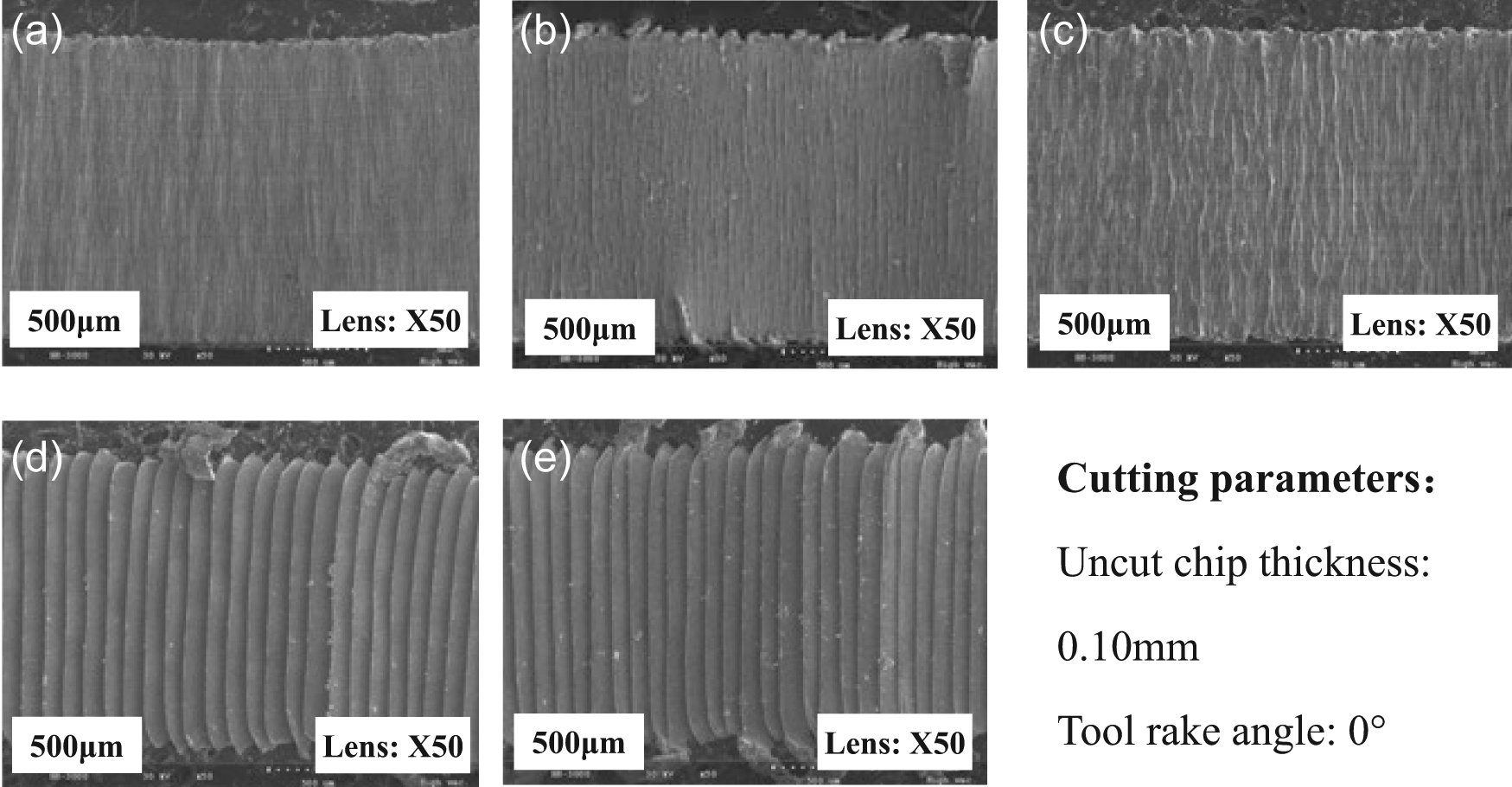
Figure 1 shows the low-magnification electron micrographs of AISI 1045 chip free surface obtained under different cutting speeds. It can be seen from Figure 1(a) and (b) that the free surface of chip is relatively smooth when the cutting speed is low. With the cutting speed increasing, folds are formed on chip free surface until the cutting speed reaches the critical value at which chip morphology becomes serrated. It is demonstrated from Figure 1(d) and (e) that regular layers emerge on the free surface, and the distance between neighboring layers decreases with the cutting speed increasing further. In addition, for serrated chips obtained under high cutting speeds, fracture and curling phenomena appear situated in chip flanks.
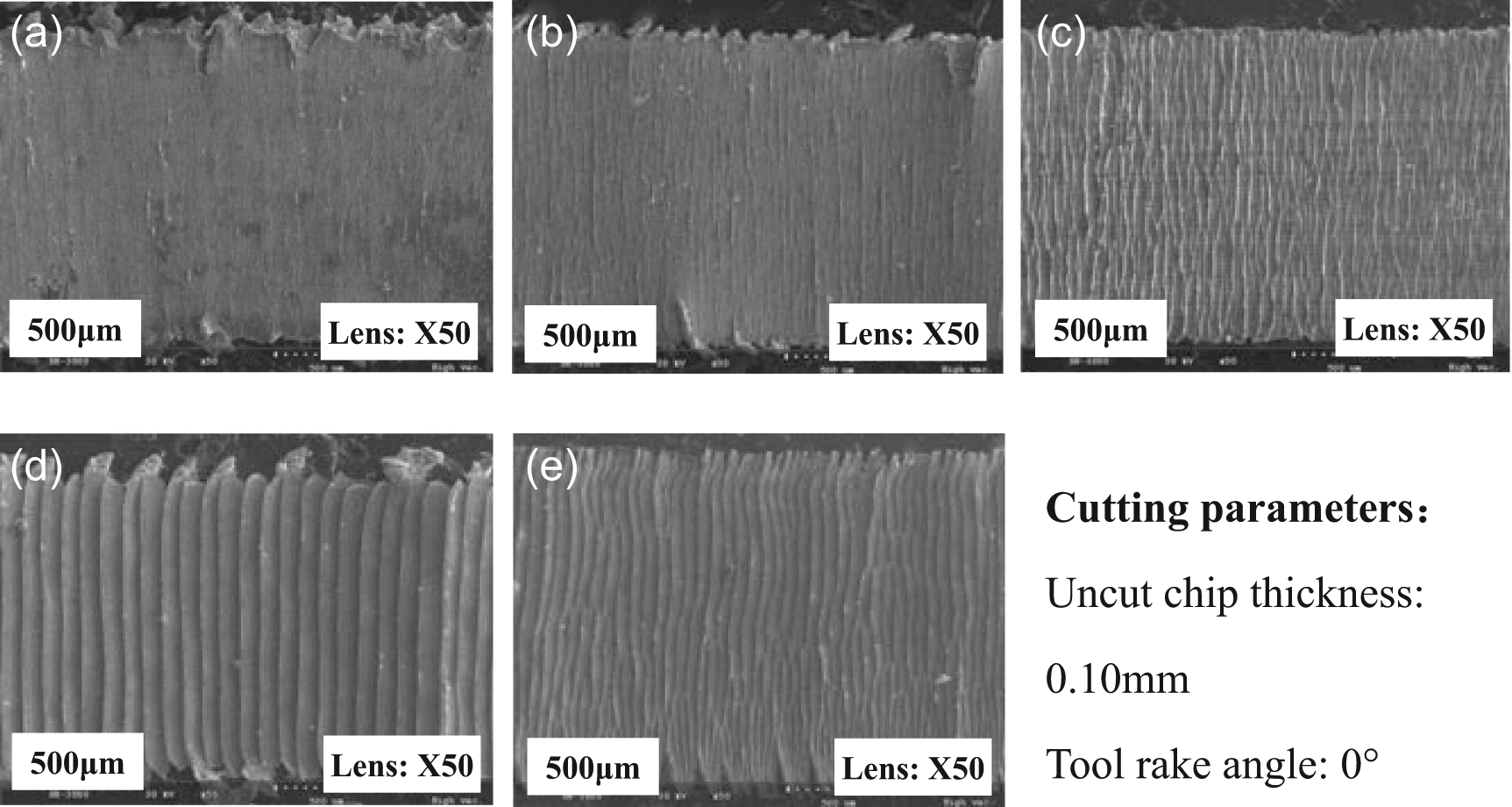
Low-magnification electron micrographs of AISI 1045 chip free surface obtained under different cutting speeds: (a) 100, (b) 200, (c) 300, (d) 800 and (e) 1000 m/min.
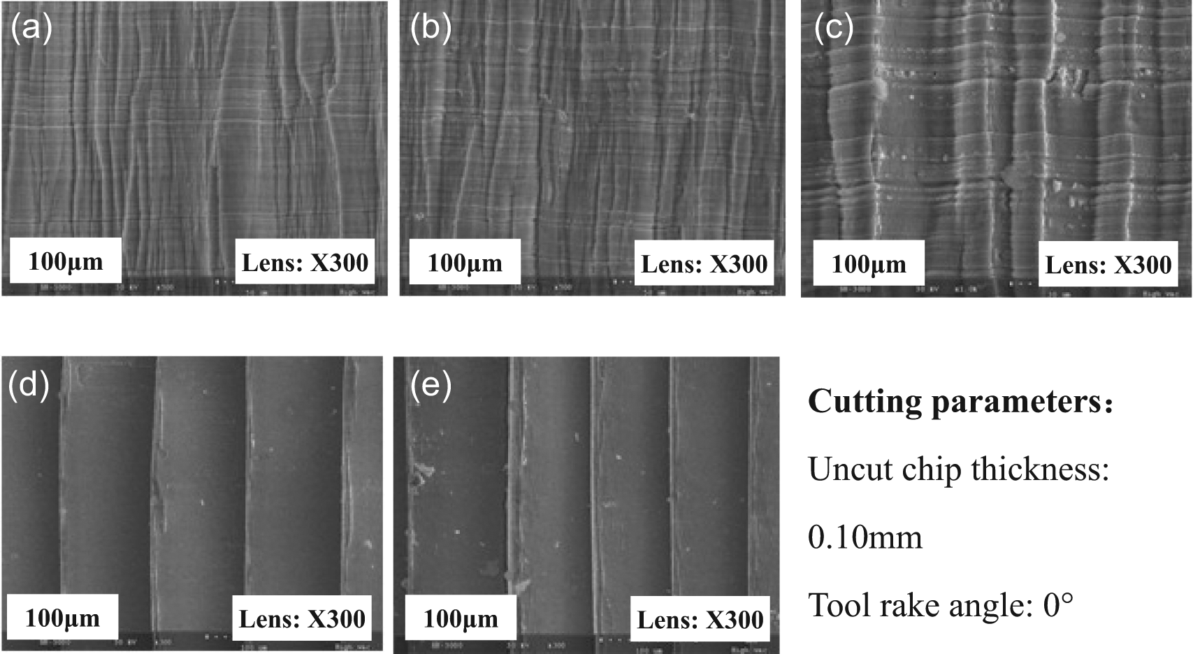
However, when the chip free surface of AISI 1045 steel was observed under high magnification, as shown in Figure 2, some interesting results present that the free surface of continuous chip consists of frequently arranged lamellae structures rather than completely flat. The average lamellae spacing increases from 2.5 µm at the cutting speed of 100 m/min to 4 µm at the cutting speed of 200 m/min. Prior to the onset of serrated chips, which are caused by the increase of cutting speed or feed rate, the fold-type structure was observed on the chip free surface. With the cutting speed increasing further, beyond which the folds are formed, the chip morphology changes to serrated whose free surface appears distinct segmentation. Compared with normal serrated chips, the fold-type ones have such an obvious difference as no shear slip observed on the free surface. It can be concluded that fold-type chip is a transitional morphology between the evolvement from continuous chip to serrated chip. Consequently, the formation of fold-type chip can also be attributed to the enhancement of thermal softening as well as the reduction of strain and strain rate hardening.
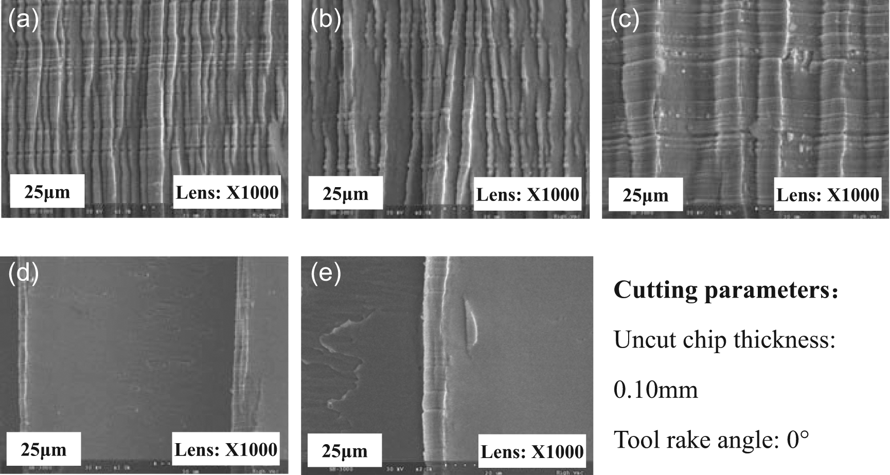
High-magnification electron micrographs of AISI 1045 chip free surface obtained under different cutting speeds: (a) 100, (b) 200, (c) 300, (d) 800 and (e) 1000 m/min.
Figures 3 and 4 display the low- and high-magnification electron micrographs of 7050-T7451 aluminum alloy chip free surface obtained under different cutting speeds, respectively. Compared with hardened AISI 1045 steel, 7050-T7451 aluminum alloy has superior plasticity and toughness. Its thermo-physical property is also better, which results in different microstructures between the two workpieces’ chips. It can be noted that fold structure has been observed under low cutting speed of 100 m/min. The lamellae structure, which is similar to Figure 2(a) and (b), is not observed. But it can be supposed that the lamellae structure may occur in lower cutting speed than 100 m/min. With regard to the serrated chips obtained under high cutting speed, the layer structure is analogous as AISI 1045 steel. On the slide surface of serrated segments, two separated zones with distinct boundary are observed: one is the ductile fracture zone on the upper region of the primary shear zone and another is the adiabatic shear zone on the lower region of the primary shear zone.
Low-magnification electron micrographs of 7050-T7451 aluminum alloy chip free surface obtained under different cutting speeds: (a) 100, (b) 400, (c) 1000, (d) 2000 and (e) 2500 m/min.
High-magnification electron micrographs of 7050-T7451 aluminum alloy chip free surface obtained under different cutting speeds: (a) 100, (b) 400, (c) 1000, (d) 2000 and (e) 2500 m/min.
The occurrence of ductile fracture within the upper region of the primary shear zone is mainly affected by the cutting speed. A conclusion can be drawn from Figures 2 and 4 that the area of ductile fracture increases with cutting speed increasing. Figure 5 shows high-magnification electron micrographs of slide surface on serrated segments of the investigated two workpiece materials. The distinctly different microstructures within the upper and lower regions of the primary shear zone attribute to their different formation mechanisms. During the chip formation, removed layer material is extruded by cutting tool, and the upper region of primary shear zone in the vicinity of the free surface experiences large plastic deformation. When the deformation exceeds the fracture strain of workpiece material, the upper region of primary shear zone starts to form crack and slides out of the chip matrix. This is the reason to explain the formation of ductile fracture within upper region of primary shear zone. At the same time, the adiabatic shear begins to initiate in the vicinity of the tool tip and propagates to the chip free surface, which leads to the formation of lower region of primary shear zone. It can be noted from Figure 5 that evident dimples distribute within the lower region of primary shear zone. This can be explained that void nucleation, grow and coalescence take place sequentially during the adiabatic shear process. It is well known that dimple shapes depend on the stress state and fracture mode. And the dimple can be divided into three subcategories such as equal-axis dimple, shear dimple and tear simple. It can be seen from Figure 5 that the dimple shape is parabolic and the flow direction of dimples is parallel to the shear direction, which illustrates that the dimples within the lower region of primary shear zone belong to the type of shear dimple.
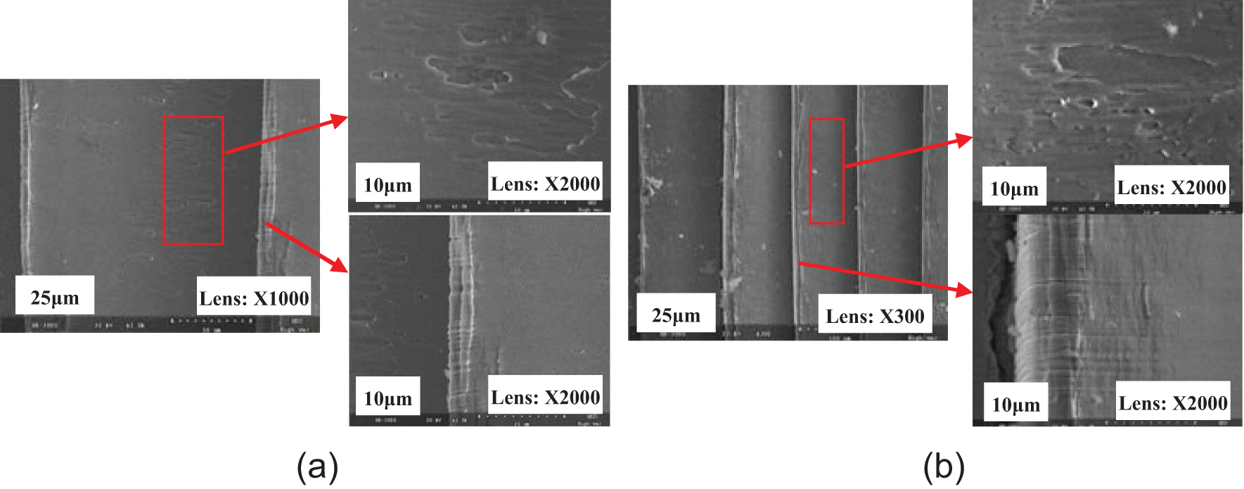
High-magnification electron micrographs of slide surface on serrated segments: (a) workpiece: hardened AISI 1045 steel, cutting speed: 800 m/min and uncut chip thickness: 0.10 mm and (b) workpiece: 7050-T7451 aluminum alloy, cutting speed: 2500 m/min and uncut chip thickness: 0.10 mm.
Through analyses of microstructure of chip free surface, it can be known that the main factor governing the transition from continuous chip to serrated chip is the initiation of adiabatic shear within the lower region of primary shear zone, when the thermal softening takes priority compared to strain and strain rate hardening. As the transitional chip morphology, the formation of fold-type chips can also be attributed to the thermal softening. When the forming condition of fold-type chips satisfies, micro shear produces within the lower region of primary shear zone. It is proposed that micro shear may be a precursor of the formation of adiabatic shear. 28 Therefore, micro shear is the predominant factor to produce fold-type chip as well as the symbol of adiabatic shear initiation near tool tip. The fold-type chip can be regarded as the transitional morphology when the chip evolves from continuous to serrated type.
Figure 6 summarizes the evolution of chip morphology with cutting conditions and material behavior in primary shear zone. This figure illustrates that with the cutting conditions changing, for example, with different properties of workpiece materials or increasing of cutting speed and feed rate, the chip morphology will evolve from continuous to serrated. When the property of workpiece material shifts from plastic to brittle under some cutting conditions such as enough high cutting speed, the fracture mechanism of chip segments will change to brittle cleavage fracture (as emphasized by red dotted box in Figure 6). Figure 6(b) and (c) presents micrographs of chip free surface and cross section under different cutting speeds.
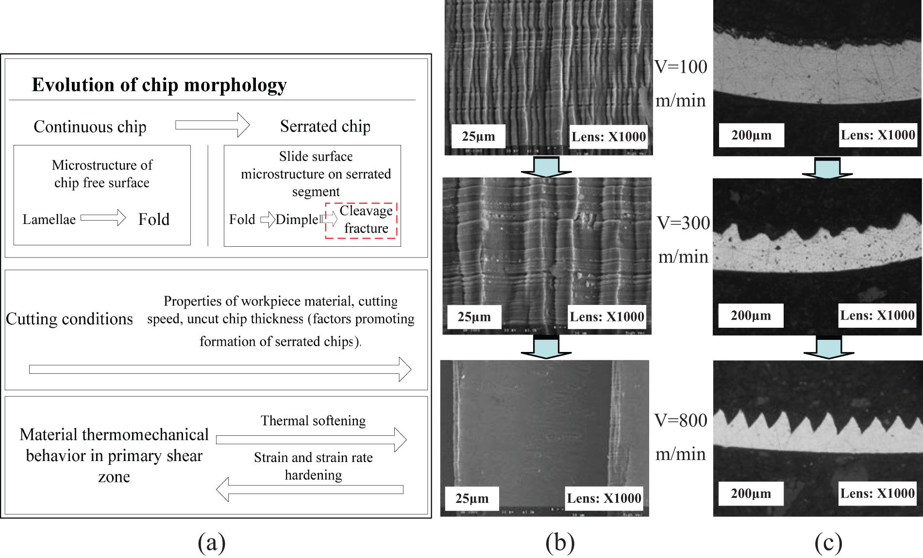
(a) Evolution of chip morphology with cutting conditions and material behavior in primary shear zone, (b) electron micrographs of chip free surface produced from AISI 1045 under different cutting speeds, uncut chip thickness of 0.10 mm and (c) optical micrographs of chip cross sections obtained under cutting conditions the same as (b).
New proposed model of serrated chip formation
As discussed about the microstructure of serrated chips above, it is found that both the two existing theories of adiabatic shear theory and periodic crack theory are insufficient to explain the serrated chip formation process. The two theories can stand up in some specific cutting conditions, while both of them have narrow limitations from generalized level. A new model to explain the serrated chip formation is proposed here based on the experimental results to eliminate the gaps of existing theories.
Figure 7 shows the new model of serrated chip formation, which is based on the mixed mode of ductile fracture and adiabatic shear. The first stage of the serrated chip formation is taken as the upsetting of the incipient segment (Figure 7(a)). The degree of upsetting prior to catastrophic failure determines the fracture mechanism of the new segment subsequently. As a result, the first task is to determine two conditions in two located Zones A and B, as shown in Figure 7(b). The first step is to judge whether the degree of plastic deformation near free surface in Point A exceeds the fracture criterion. The second step is to judge whether the condition for adiabatic shear is satisfied in the vicinity of tool tip Point B. Different judgment results deduce different types of chips.
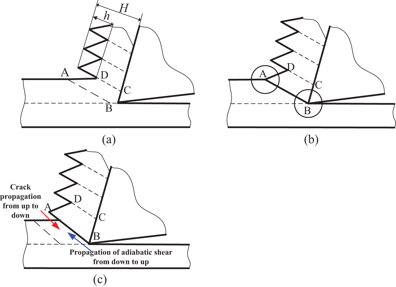
New model of serrated chip formation. In (a) h is the vertical distance between the valley and the peak of serrated section, and H is the maximum height of the serrated chip
When the cutting speed is low, both the two conditions could not satisfy so there is neither cracks generating in free surface nor adiabatic shear occurring near tool tip. Consequently, the removed layer material undergoes homogeneous deformation and continuous chips are then formed. With the cutting speed increasing, the second condition satisfies while the first one does not. Adiabatic shear initiates from tool tip and propagates to free surface with the tool moving. The strength of primary shear zone weakens until catastrophic failure happens to form “adiabatic shear serrated chips.” With the cutting speed increasing further, both the two conditions satisfy simultaneously. Ductile fracture takes place in free surface while adiabatic shear initiates from tool tip, and both of them propagate in opposite directions (as shown in Figure 7(c)). Ductile fracture will terminate due to the improvement of material toughness caused by thermal softening. The propagation length of ductile fracture and adiabatic shear depends on the cutting conditions and material properties. In this situation, the formed serrated chips can be called “ductile fracture–adiabatic shear serrated chips.” When the cutting speed is in ultra high speed range, the degree of plastic deformation near free surface meets with material fracture criteria prior to the adiabatic shear initiating from tool tip. In addition, with the variation of stress state and strain rate in the primary shear zone, the material property changes from plastic to brittle. This results in the brittle cleavage fracture between successive segments instead of ductile fracture. And the chip morphology may shift from serrated chips to fragmented ones.
Influence of cutting speed and feed rate on chip serration
Based on the chip morphology obtained under different combinations of cutting speed and feed rate, it can be concluded that both cutting speed and feed rate are dominant factors to influence the onset of adiabatic shear for given workpiece materials. In order to investigate the serrated chips quantitatively, the degree of chip segmentation, which is defined as the ratio of h to H (as shown in Figure 7(a)), is adopted. The parameter h is the vertical distance between the valley and the peak of serrated section, and H is the maximum height of the serrated chip. Figure 8 shows the effects of cutting conditions on the degree of chip segmentation produced from cutting tests of two materials. It can be seen that the degree of chip segmentation increases as the cutting speed or feed rate increases. AISI 1045 steel is prone to produce serrated chips under relative low cutting speed, while the cutting speed should be higher if the serrated chips are desired to achieve when 7050-T7451 aluminum alloy is machined.
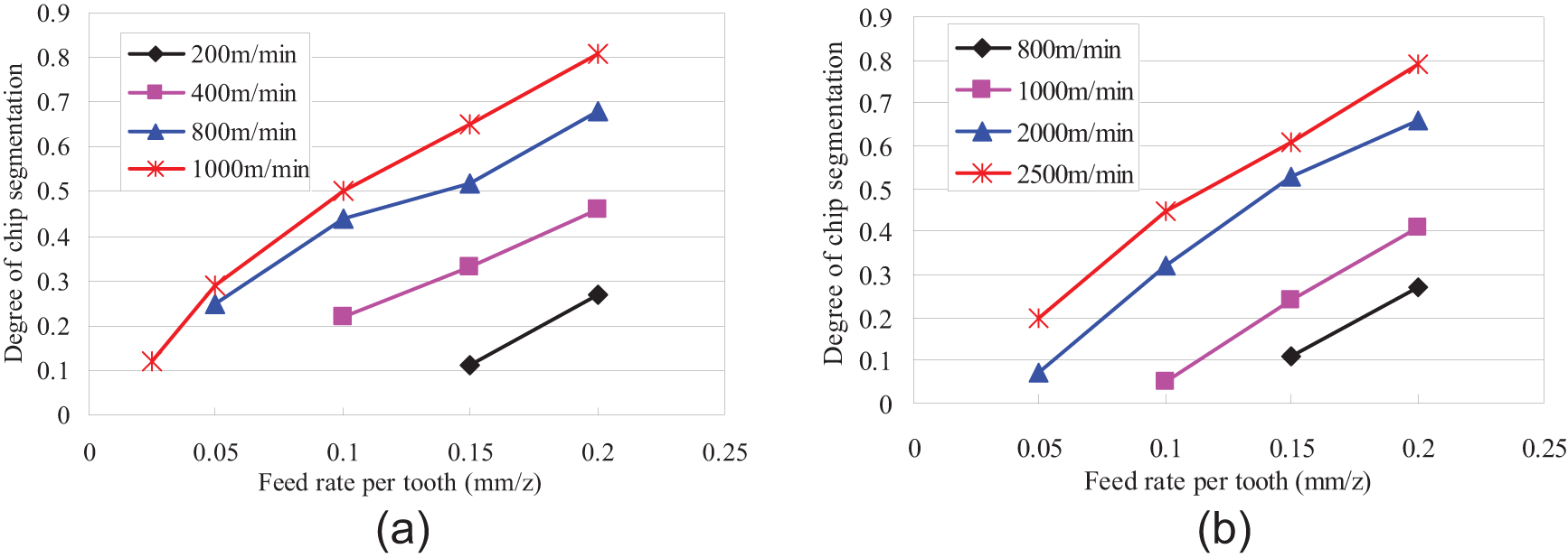
Effects of cutting conditions on the degree of chip segmentation: (a) AISI 1045 steel and (b) 7050-T7451 aluminum alloy.
For AISI 1045 steel, when the cutting speed is 100 m/min, there is no serrated chip observed in all ranges of experimental feed rate per tooth as 0.025–0.20 mm/z. As for the cutting speed of 200–400 m/min, only at the feed rate per tooth as higher than 0.1 mm/z may the serrated chips occur. But when the cutting speed increases to 1000 m/min, the serrated chips can be achieved in feed rate per tooth of 0.025–0.20 mm/z invariably. With regard to 7050-T7451 aluminum alloy, the transition from continuous chip to serrated chip is hardly observed when the cutting speed is less than 800 m/min. When the cutting speed increases to 2000–2500 m/min, the serrated chips can be obtained in the feed rate per tooth of 0.05–0.20 mm/z.
Critical cutting load for serrated chip formation
It is found that serrated chips are not always created at different cutting conditions. It can be shown from Figure 8 that different cutting speeds correspond to different feed rates per tooth at which the serrated chips are produced. In previous investigations, many researchers have been dedicated to the study of critical cutting speed for serrated chip formation. It is proved in this study that only critical cutting speed is insufficient to describe the cutting conditions for the formation of serrated chips. The experimental results show that both cutting speed and feed rate have significant effects on the onset of adiabatic shear. Critical cutting load is proposed in this article to illustrate the conditions under which serrated chips may occur. The critical cutting load is the multiplication of cutting speed and feed rate per tooth (or uncut chip thickness, here the two parameters are equal). Different materials correspond to different critical cutting loads, which is a useful governing parameter for the purpose of chip control and disposal in automatic machining process. Figure 9 shows the critical feed rate per tooth under different cutting speeds when the serrated chips occur for the two materials. It can be concluded through curve fitting that the critical cutting loads are 0.024 and 0.10 m2/(min z) for hardened AISI 1045 steel and 7050-T7451 aluminum alloy, respectively. This also indicates that hardened AISI 1045 steel is prone to produce serrated chips than 7050-T7451 aluminum alloy.
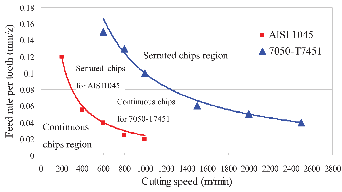
Critical cutting load to form serrated chips.
Conclusion
This article presents the morphology of chip free surface obtained at different combinations of cutting speed and feed rate. The microstructure of slide surface on serrated segment was observed and analyzed. The transition from continuous to serrated chips was studied in terms of critical cutting load. And a new model of serrated chip formation was proposed based on mixed mode of ductile fracture and adiabatic shear. Such conclusions can be summarized as below:
The morphology of chip free surface is observed to evolve from lamellae to folds and then to dimples. The fold-type chips can be regarded as transitional morphology from continuous chips evolving to serrated chips.
The mechanism of serrated chip formation is proposed based on the mixed mode of ductile fracture and adiabatic shear. According to this, the serrated chip can be divided into “adiabatic shear serrated chips” and “ductile fracture–adiabatic shear serrated chips.” With regard to the latter type, such two distinct zones as ductile fracture zone and dimples distribute on the slide surface of serrated segment.
It is concluded that cutting speed and feed rate are dominant factors to influence the onset of adiabatic shear for the given workpiece materials to be machined. And the degree of chip segmentation has positive correlation with cutting speed and feed rate.
The critical cutting load, which is defined as the multiplication of cutting speed and feed rate per tooth, is proposed to illustrate the conditions under which serrated chips may occur. The study indicates that the critical cutting loads for AISI 1045 and 7050-T7451 aluminum alloy are 0.024 and 0.10 m2/(min z), respectively.
Footnotes
Declaration of conflicting interests
The authors declare that there is no conflict of interest.
Funding
This study was financially supported by the National Basic Research Program of China (2009CB724401), National Natural Science Foundation of China (U1201245) and the Major Science and Technology Program of High-end CNC Machine Tools and Basic Manufacturing Equipment (2012ZX04003-041).