
Abstract
In the present work, a hybrid modular machining technology was designed for machining of Ti6Al4V alloy. Ultrasonic machining was integrated with vortex tube based spot cooling system with CO2 gas as working fluid for achieving the cumulative advantage of both, which is termed as Spot Cooled Vibration Assisted Turning (SCVAT). Its performance is evaluated and compared with Conventional turning, Vibration Assisted Turning and Vortex tube based spot cooling under constant machining conditions. The vibration and cooling parameters were also kept constant wherever applicable. The results showed a significant reduction in cutting temperature (30.98%), surface roughness (65.97%), and tool wear (75.03%); however, cutting forces are increased slightly compared to dry cutting. Compressive surface residual stresses were generated on the machined surface in SCVAT.
Keywords
Introduction
Titanium alloys are widely used aerospace materials and also one of the most difficult to cut materials. These are also widely used in automobile industries and by implant manufacturers. The properties of the alloys which attract the industry are the same reasons for poor machinability characteristics. Some of these properties include low thermal conductivity, high chemical affinity, high hardness, and high strength. 1 Higher cutting forces, poor surface finish, high cutting temperatures, enhanced tool wear are the resulting effects of the aforementioned properties. The heat generated at the cutting zone is identified to be one of the key issues to address while machining Ti alloys. Research in this area gained importance leading to the development of techniques like minimum quantity lubrication (MQL)2–4 and cryogenic cooling in addition to conventional flood cooling.
Cryogenic cooling in the recent times has come to occupy a major role in cooling techniques because of its advantage compared to flood cooling as well as MQL. The commonly used cryogenic fluids are Liquid nitrogen (LN2), 5 Liquid carbon dioxide (LCO2), 6 CO2 snow. 7 The role of cryogenic fluid in improving surface integrity was studied by Shokrani et al. 8 End milling of Ti6Al4V was performed under dry, wet and cryogenic conditions with super cooled LN2.The study evidently proved that cryogenic cooling improved surface finish by 39% and 31% compared to dry and wet conditions. Hari Chealvan et al. 9 studied the effect of high pressure cryogenic LN2 in high speed drilling of Ti6AL4V and reported a reduction in cutting temperature and surface roughness. The ability of the coolant to intrude into the tool work interface due to high pressure is attributed to the improvement of the aforementioned responses. In the experimental investigations carried out by Jadhav and Mohanty, 10 MQL and cryogenic cooling were compared while machining Nimonic-C263 alloy in terms of surface roughness, tool wear and cutting forces. It was identified that surface roughness and tool life improved by 18.7%, 6.5% respectively while cutting force was reduced by 30% in cryogenic machining compared to MQL. In the experimental work carried out by Pereira et al. 11 cryogenic CO2 was used as external and internal coolant in machining Inconel 718. In addition, MQL and CryoMQL with CO2 as working fluid were also studied. The cutting forces and tool wear were evaluated and it was concluded that, providing CO2 as internal coolant makes it very eco-friendlier and efficient. In the study conducted by Jamil et al., 12 CO2 snow and Cryogenic LN2 were compared for heat transfer efficiency in machining Ti alloy. In this work, tool wear, cutting forces, surface roughness, and chip curl diameter were studied. The convective heat transfer coefficient was larger in CO2 snow and hence cutting temperature was reduced by 14%–20% in comparison with LN2, but as the cutting speed increases, the temperature difference reduced. In addition, tool wear was lower in CO2 snow cooling.
Also the physical parameters of cooling like nozzle diameter, its orientation and the number of nozzles adopted, play a key role in machining. 13 The role of single and dual jets used in providing cryogenic LN2 was studied by Mia and Dhar 14 while turning Ti alloy. It was discovered that dual jets performed better than mono jet as the former provided more effective cooling at the cutting zone. The role of nozzle radius and nozzle orientation was studied by Nouzil et al. 15 in turning super alloy Inconel 718.The study also included cutting speed as a variable along with nozzle variables. It was identified that as the nozzle radius increased, cutting forces were increased. This is attributed to an increase of strain hardening effect of material. However, higher nozzle radius was preferred for reducing the average cutting temperature.
In addition to application of MQL and cryogenic cooling, recent literature has cited the use of Ranque−Hilsh Vortex tube (RHVT) for upgradation of the above processes. This technique also proved to be fruitful in achieving the desired results and for sustainability. In the experiments conducted by Singh et al., 16 Ti-3Al-2.5V was machined with coated carbide inserts adopting RHVT and this was compared with MQL. Compressed air was used as the working medium in RHVT. It was concluded that RHVT is more sustainable than MQL because of the generation of particulate matter in the latter. Though tool wear and surface roughness reduced with RHVT in comparison to dry turning, better results were obtained from MQL than RHVT. In the studies carried out by Kuila and Melkote 17 on Laser Assisted Micro Milling (LAMM) of A286 steel, MQL and vortex tube cooling were adopted. It was concluded from the study that LAMM with vortex tube reduced the average cutting force by 15% than LAMM and the burr size was reduced too. Mahapatro and Krishna 18 adopted vortex tube cooling system with CO2 gas in machining Ti6Al4V alloy. The incorporation of vortex tube in the work led to lower temperature at the cutting zone and improved the surface finish. In addition, higher pressure of the coolant was seen as a better choice for machining.
Apart from application of cutting fluids and cooling conditions in different forms, the modification of the machining process itself, was studied in the literature while machining Ti alloys. This includes providing assistance to the existing machining processes in the form of external heat, vibration etc. Laser assisted machining (LAM),19,20 hot turning, 21 and ultrasonic machining22,23 were some of them. In ultrasonic machining, ultrasonic vibrations of low amplitude, and high frequency were applied to the cutting tool in ultrasonic assisted machining(UAM). The intermittent cutting resulting from the applied vibrations are responsible for the reduction of cutting forces and cutting temperatures,23,24 improved tool life25,26 and surface finish. 27 Also the role of amplitude 28 and frequency 29 were thoroughly studied and their importance discussed extensively in the literature. In vibration assisted turning experiments of Ti6Al4V conducted by Venkata Sivareddy et al., 30 the tool work contact ratio (TWCR) governed by amplitude was identified as the major contributor for process improvement. Khajehzadeh et al., 31 machined AISI 1040 hardened steel using 1-D and 2-D vibration assisted turning and evaluated tool wear at different amplitudes of vibration. It was concluded from the study that, the reduction in flank wear improved by 15% with increment in amplitude from 5 to 13 µm. The critical speed always limits the maximum cutting speed in UAM, as its advantage gets minimized once the cutting speed approaches critical speed. In the studies carried out by Zhang et al. 32 an attempt was made to increase the cutting speed beyond the critical speed by applying vibrations in the feed direction. The high speed ultrasonic vibration cutting thus developed successfully improved tool life, surface finish and cutting efficiency.
As the demand for sustainability in machining increases, the attention has shifted toward hybrid techniques in recent times. The hybridization involves integration of two or three individual techniques in order to derive the cumulative advantage of all the techniques. The recent literature includes minimum quantity cooling lubrication-MQCL (MQL + low temperature air, 33 MQL + cooling additives 34 ) minimum quantity cooling lubrication with vortex tube (MQL + RHVT), 35 ultrasonic vibration assisted machining with MQL and cryogenic cooling (UAM + MQL + Cryogenic), 36 Cryogenic ultrasonic assisted turning − CUAT (ultrasonic assisted turning + cryogenic cooling). 37 Life cycle assessment studies were conducted by Gupta et al. 38 in machining Ti alloy using integrated RHVT + MQL technique. The proposed technique yielded better performance in improving machining characteristics and also proved to be more sustainable than MQL. Better heat dissipation due to the flow of cooled cutting fluid at the tool-work and tool-chip interfaces in RHVT + MQL was attributed to the improved results. In the research work authored by Ni and Zhu, 39 ultrasonic machining was combined with MQL in milling TC4 alloy. Two nozzles were adopted for coolant supply at the cutting zone and the work piece was vibrated. The study showed an increase in surface finish by nearly 50% and 30% compared to conventional and ultrasonic assisted machining. The success of UAM + MQL technology is attributed to effective cooling achieved due to the combined effect of tool separation and coolant supply. Integration of ultrasonic assistance with cryogenic cooling termed as Cryogenic Ultrasonic Assisted Turning (CUAT) was done by Khanna et al. 37 LN2 gas was directed on to the vibration insert while turning Nimonic 90. CUAT was seen as a superior technique to Cryogenic Assisted Turning (CAT) as it led to 20% lower energy consumption, 29% lower surface roughness and reduced carbon emissions. Machining cost was also lower in case of CUAT than CAT. In the work by Airao et al., 40 Ultrasonic Assisted Turning (UAT) in conjunction with MQL and LCO2 separately were adopted in machining Ti6AL4V. It was concluded that UAT with LCO2 reduced flank wear, power consumption and surface roughness when compared with dry, wet and MQL strategies. Yip et al. 41 developed a hybrid technique for machining Ti alloy by integrating ultrasonic machining with magnetic field. It was observed that the application of magnetic field suppressed cutting scars generated during ultrasonic machining that eventually improved the surface quality of the machined surface. In the experimental work conducted on machining Ti6Al4V by Agrawal et al., 36 sustainability assessment of integrated techniques viz. UAT + Cryogenic and UAT + MQL + Cryogenic in terms of surface finish, cost of machining and energy consumption was carried out and the same was compared with cryogenic machining. It was concluded that integrated techniques achieved an improvement in surface finish by 42% compared to cryogenic machining. It was also identified that hybrid techniques were more energy efficient than cryogenic machining.
Interpreting the above literature, it is clear that a lot of work has been reported in the areas of MQL, UAM, RHVT, cryogenic cooling individually. However, the combinations termed hybrid techniques has been found to be very beneficial and sustainable, is still under research and gaining importance in recent times. Exploration of various fluids in RHVT for machining applications is seldom found. In addition, UAM based hybrid techniques have also been less explored when compared to others. Thus, in this work, an attempt is made to develop a sustainable and improved hybrid technique labeled Spot Cooled Vibration Assisted Turning (SCVAT) by integration of vortex tube based spot cooler with CO2 gas as working fluid and VAT. The reasons to choose CO2 gas are its stability at room temperature, fewer storage difficulties and high Joule Thompson coefficient. 42 It also produces lower temperatures than compressed air in a vortex tube. Furthermore, the vortex tube based cooling setup requires low initial investment and is easy to maintain. This work also involves design aspects in developing the proposed hybrid technique followed by its evaluation. The idea is to take advantage of all the processes integrated and countering the limitations of one by the other, as is evident from experimental observations. The turning experiments on Ti6Al4V were carried out under conventional dry machining (CT), Vibration Assisted Turning under dry environment (VAT), Vortex Tube Based Spot Cooling (VTSC), and Spot Cooled Vibration Assisted Turning (SCVAT) with gaseous CO2 as cutting fluid. The performance of each process was evaluated and compared in the sections that follow.
Design of spot cooled vibration assisted turning (SCVAT)
Principle of SCVAT
The conceptual visualization of SCVAT process is shown in Figures 1 and 2. In the approach stage the tool starts from initial position “o” and comes in contact with workpiece at time t1 and position P1. In stage 2, the tool moves forward cutting the workpiece up to time t2 and reaches position P2 where it starts changing its direction. In stage 3, the tool moves away from the workpiece up to its maximum displacement in the negative direction thus completing one cycle of vibration, which is then succeeded by a new cycle. The supply of coolant to the cutting zone takes place throughout the cycle continuously. Heat dissipation is also conceptually plotted in Figure 2. It can be observed that the coolant flow in SCVAT is similar to conventional turning in stages 1 and 2 that is, from tool position P1 to P2. Hence the heat dissipation is also similar as depicted by blue and red lines between h1 and h2. But during stage 3, because of the tool-work separation explained above, the coolant easily flows into the interface region, thereby cooling the cutting tool and machined surface more effectively. This enhances the heat dissipation in SCVAT as indicated by the red line from h2′ to h3′. In conventional turning, since the cutting is continuous, heat dissipation is from h2 to h3 which is lower than the former. Thus SCVAT in principle would augment heat dissipation rate as it facilitates better coolant flow in the tool-work interface.
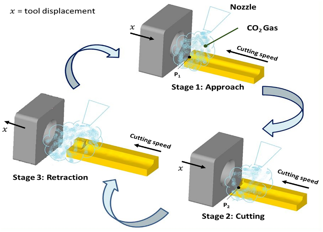
Schematic illustration of spot cooled vibration assisted turning (SCVAT).
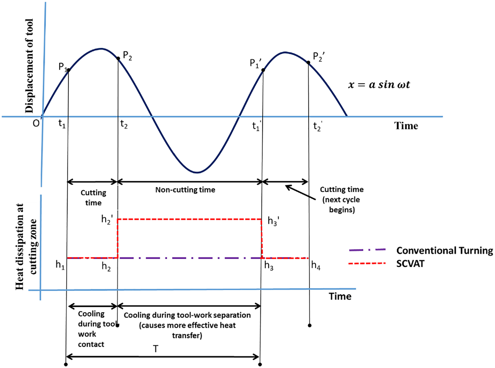
Tool displacement and heat dissipation in SCVAT.
Components of SCVAT
The proposed hybrid system consists of a conventional lathe machine (Make: MAGNUM Tools,10 HP capacity) retrofit with components for applying cooling and vibrations to the tool simultaneously. The cooling system peripherals include CO2 gas cylinder, pressure gage, insulated pipes, vortex tube based spot cooler, and dual nozzle setup. CO2 gas is contained in a cylinder at a pressure of 35 bar. The cylinder is fitted with a pressure gage in order to monitor the inlet pressure. A lever operated knob is provided to the cylinder for opening and closing the flow of CO2 gas to the system. Glass wool (k = 0.0372 W/m K), 43 one of the widely used insulating material in industry is used for insulation of the rubber hose connecting to the vortex tube, thereby reducing heat loss to the surroundings.
This vortex tube based spot cooler (Make: EXAIR corporation; Model : BP 3725) shown in Figure 3(a) lowers the temperature of CO2 gas through the principle of vortex tube.44,45 This device is also provided with an adjustment knob (controller) for varying the quality of cold CO2 gas at the cutting zone. Temperatures as low as −35°C to −50°C can be achieved with this device. The nozzle setup consists of two identical convergent nozzles, placed one on either side of the tool tip inclined at an angle of 45°. The distance from the tip to the nozzle is 35 mm. This nozzle configuration was chosen based on the author’s previous work. 18 The nozzles were 3D printed with a 3D printer (Make and Model: Ultimaker 2+) using Poly Lactic Acid (PLA) material. The diameter of each nozzle is 6 mm and length is 30 mm as shown in Figure 3(b). These were connected to the vortex tube based spot cooler through a flexible hose.
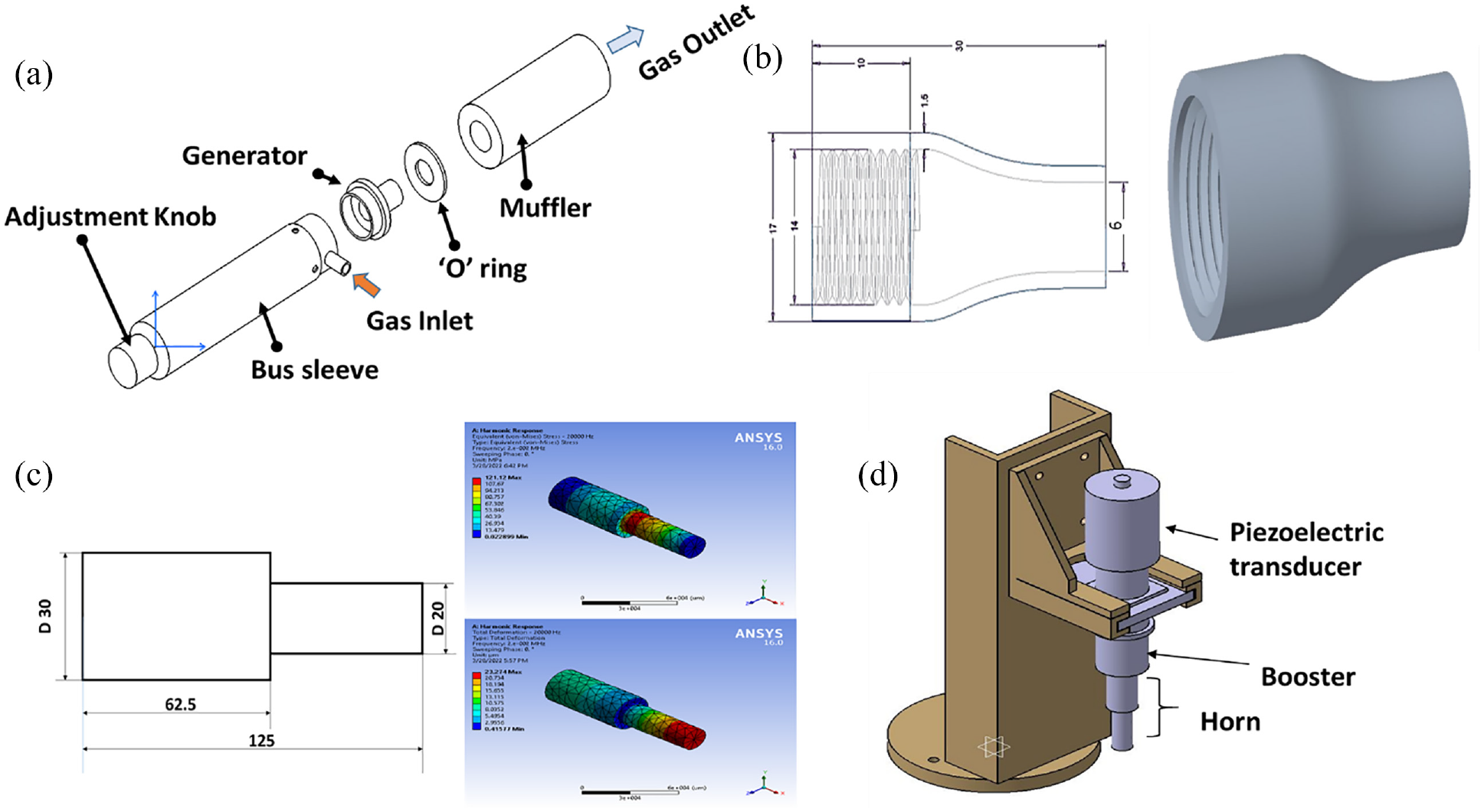
(a) Vortex tube based spot cooler, (b) nozzle, (c) horn, and (d) holder for transducer and sonotrode assembly.
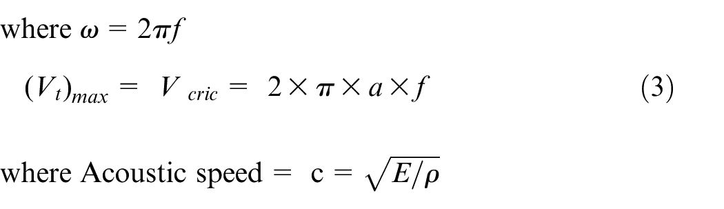
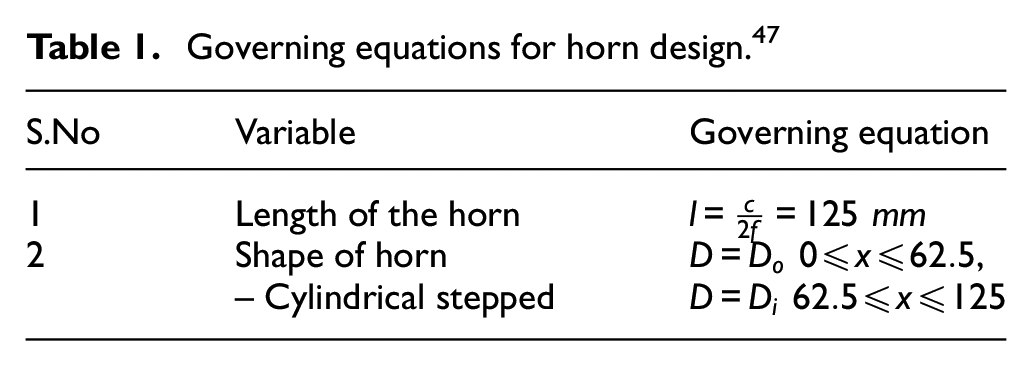
The vibration assisted turning setup (Make: RTUL− Roop Telsonic Ultrasonix Ltd; Model: SERIES SG-22; 4.5 kW and 20,000 Hz) consists of a generator, high frequency cable, transducer, booster and horn (sonotrode). The generator supplies electrical energy at the designed voltage to the piezoelectric transducer. The transducer converts this into mechanical energy in the form of vibrations of low amplitude and high frequency. This amplitude is further amplified by the booster and also by the horn to vibrate the cutting tool in the tangential direction. The horn also known as concentrator is the key element in the ultrasonic turning attachment. The ultrasonic horn used in this work is made of Ti6Al4V alloy and it is resonating type. 46 The governing equations and design parameters are tabulated in Table 1. The horn was manufactured and then tested using an accelerometer attached to Indi6192 digital vibration meter. The amplitude was found to be 25 µm at the tool end for an input ultrasonic power of 100% and 20 kHz frequency. In addition, harmonic analysis was carried out using finite element method for revealing dynamic characteristics of the horn. The results showed that the maximum stress was 121.12 MPa and the magnification factor is 2.3 as given in Figure 3(c). Since the stress developed is within the endurance limit of Ti alloy (382 MPa), the design was assumed to be reliable. A special holder shown in Figure 3(d) was fabricated in-house for carrying assembled transducer and sonotrode on the lathe. The displacement and velocity of the vibrating tool are given by equations (1) and (2) respectively. The key parameter in application of ultrasonic machining is the critical speed. If the cutting speed exceeds the critical velocity (V > Vcric), tool separation will not take place and the cutting becomes continuous. As is clear from equation (3), critical velocity is a function of amplitude and frequency. 46 In this work an amplitude of 25 µm at frequency 20 kHz was used. Hence, the critical speed was 188 m/min.


Governing equations for horn design. 47
Materials and methods
The proposed hybrid cutting technique, SCVAT was compared with CT, VAT, VTSC in terms of cutting force, cutting temperature. surface finish, tool wear, and residual stresses. The materials and methods in conducting the experiments and collecting the responses are discussed in the following sections.
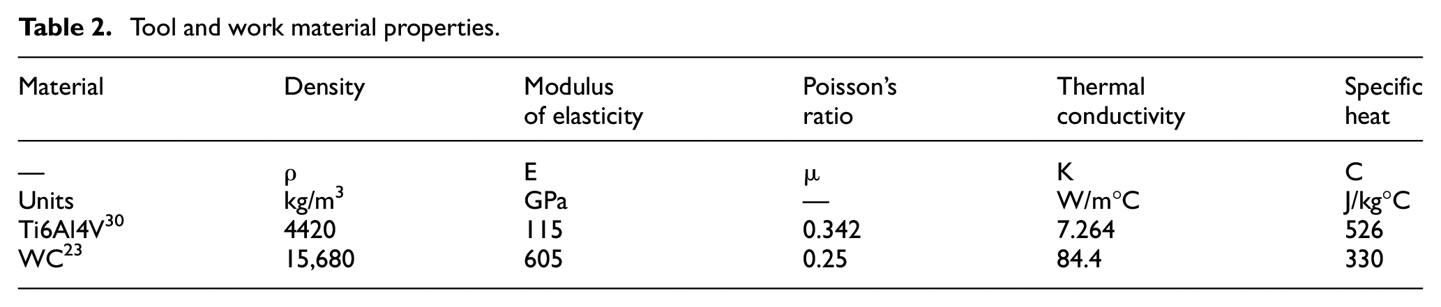
The material adopted in the study was Grade 5 Titanium alloy, Ti6Al4V.The properties of the alloy are presented in Table 2. The workpiece is a round bar of diameter 40 mm and length 240 mm. The cutting tool is tungsten carbide with rhombic −80° shape (CNMG 120408 THM) having −6° rake angle, 5° clearance angle, nose radius of 0.8 mm, cutting edge length of 12.89 mm, thickness of 4.79 mm, hole size of 5.16 mm, suitable for cutting high temperature alloys and PCLNR 2525 M12 tool holder were used for machining.
Tool and work material properties.
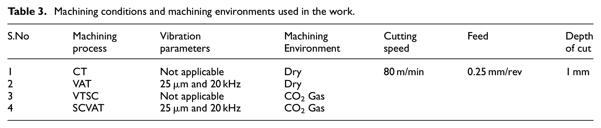
The machining, cooling and vibration parameters were chosen based on the tool work combination as per the tool supplier data and authors previous work.18,30 The machining parameters were kept constant with a cutting speed of 80 m/min, feed rate of 0.25 mm/rev and 1 mm depth of cut for CT, VAT, VTSC, SCVAT to evaluate the performance of each process under similar machining conditions. The detailed machining conditions and machining environment adopted in the work are summarized in Table 3. Dry conditions were adopted in CT and VAT while in VTSC and SCVAT, CO2 gas at a pressure of 7 bar, temperature of −20°C with a cold fraction of 20% was used. Dual nozzle system with a nozzle angle of 45° to the rake face, nozzle-tip distance of 35 mm and nozzle diameter of 6 mm was used in this study. 18 In VAT and SCVAT the amplitude and frequency of vibrations were 25 µm and 20,000 Hz respectively at 100% ultrasonic power. The experimental setup and associated equipment are shown in Figure 4(a) to (e).
Machining conditions and machining environments used in the work.
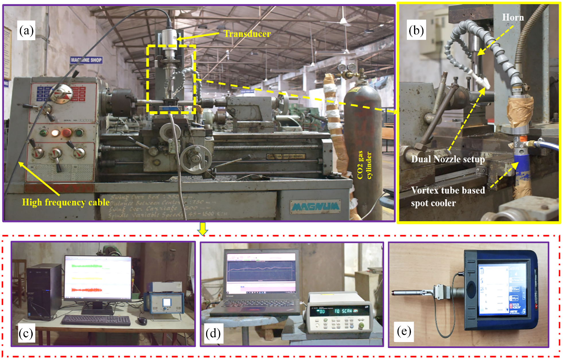
Experimental setup with SCVAT (a) lathe machine, (b) SCVAT setup, (c) dynamometer, (d) DAQ for temperature measurement, and (e) surface roughness tester.
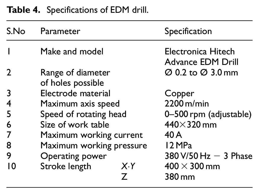
Cutting force, cutting temperature, surface roughness, tool wear, and residual stress were the key parameters chosen for evaluating the process efficiency. CO2 gas was allowed to flow through the nozzle for 90–120 s prior to cutting in order to ensure the required temperature. A thermocouple provided at the nozzle end was connected to the data acquisition system to measure the temperature of gas. Each experiment was replicated thrice. The cutting force was measured by Kistler dynamometer (9257B) with a charge amplifier (Type 5070) connected to the lathe machine as shown in Figure 4(c). For measuring the cutting temperature, a hole of 0.6 mm diameter was drilled in the tool insert as shown in the Figure 5 using EDM drill. The dimensions of the drilled hole and its location were taken from the literature. 30 The specifications of the EDM drill are given in Table 4. A K-type thermocouple with 0.25 mm diameter and uncertainty of ±1.1°C was used in the study. The measuring end was inserted in the tool and the other end was taped to a data acquisition system accompanied by a software, shown in Figure 4(d). It is noteworthy that the same technique was adopted for measuring the cutting temperature for all four machining processes studied, thereby ensuring the location at which temperature was measured was the same in all cases. The surface roughness was measured with Taylor Hobson- Surtronic S128 surface roughness tester having 50 nm resolution with tip radius of 5 microns and cutoff length of 5 mm as shown in Figure 4(e). The surface roughness was taken at three locations circumferentially and the average value was taken. For measuring tool wear, the worn tools were seen under Scanning Electron Microscope and measured using ImageJ software. For residual stresses, X-Ray Diffraction technique was adopted. The sample (10 mm ×10 mm × 5 mm) of the machined surface was EDM cut from the machined bar and cleaned with acetone to remove any dirt or debris. The residual stresses measurement was done using X ray diffraction technique and the measurements were done on the surface of the machined sample. The stress was calculated from the slope of d-sin2Ψ graph where “d” is the interplanar spacing and “Ψ” is the angle between normal to sample surface and stress component direction. 48
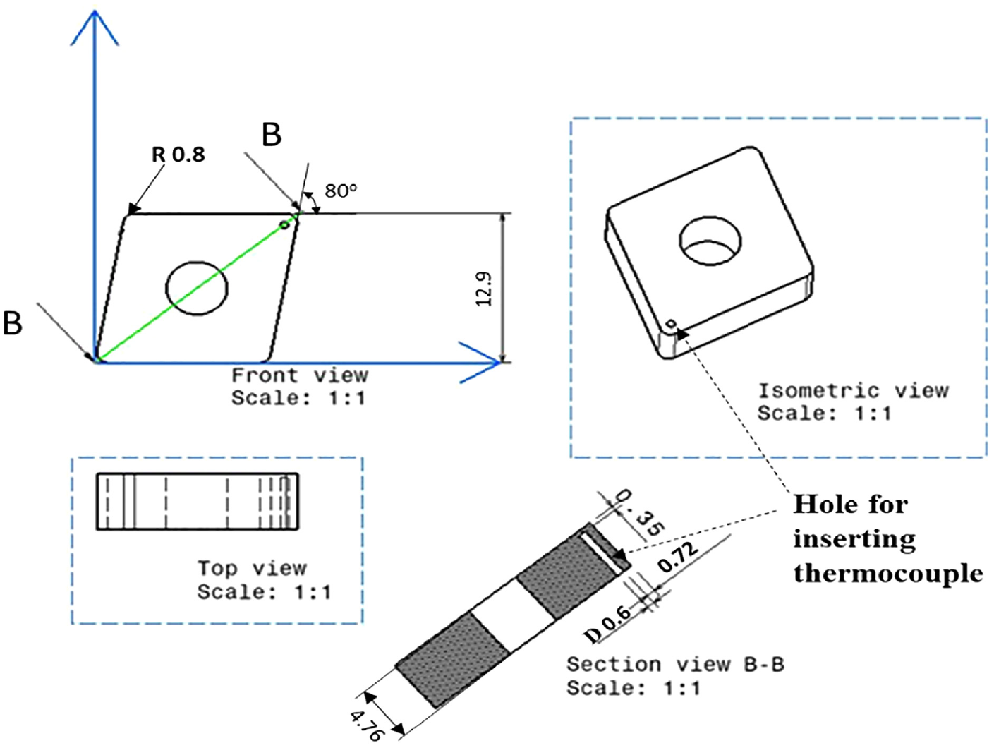
Insert with drilled hole for thermocouple attachment.
Specifications of EDM drill.
Results and discussion
The performance of the proposed hybrid cooling technology (SCVAT) was compared with CT, VAT, and VTSC. The performance was evaluated in terms of cutting temperature, cutting force, surface finish, tool wear, and surface residual stress. These are discussed in the following sections.
Cutting temperature
The cutting temperature has a direct influence on surface characteristics of the machined component. Comparison graph for cutting temperature concerning all the four processes is depicted in Figure 6. It is evident that CT under dry environment recorded highest cutting temperature followed by VAT, VTSC, and SCVAT respectively. While SCVAT showed the least cutting temperature, it was lower by 30.98%, 28.80%, and 4% than that of CT, VAT, and VTSC respectively. This can be attributed to the vibration assistance and presence of cooling medium in the process. The intermittent cutting mechanism due to ultrasonic assistance resulted in reduced TWCR. 30 The low contact time of tool and workpiece in a single cycle of cutting, led to reduced conduction heat transfer to the tool. This would also enable better convective heat transfer from the cutting zone to the surroundings which also a reason for reduced cutting temperature in VAT. 49 Additionally, SCVAT consists of pressurized CO2 gas being impinged at the cutting zone through dual nozzle setup similar to that of VTSC. This causes forced convective heat transfer to take place between CO2 gas and cutting zone. However, the tool separation from workpiece in SCVAT due to interrupted cutting allows coolant penetration into the cutting zone unlike VTSC, where the cutting is continuous. Thus convective heat transfer takes place more efficiently in the former which in turn helps avoid accumulation of heat at tool-work interface. Along with this, the high Joule Thompson coefficient of CO2 gas accompanied by further expansion in vortex tube imparts higher cooling effect even at low temperatures. 42 This allows further reduction in cutting temperature. Hence, it can be concluded that the integrated benefits of cooling and ultrasonic assistance led to superior performance of SCVAT than its constituent counterparts, viz. VAT and VTSC.
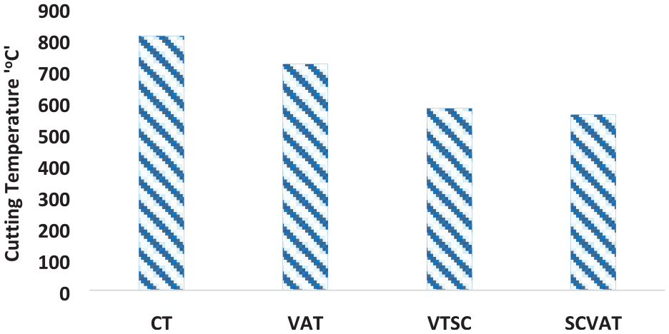
Comparison of cutting temperature in CT, VAT, VTSC, and SCVAT.
Cutting force
The behavior of cutting force is governed by strain hardening effect and thermal softening of the workpiece material. The cutting zone temperature and rate of heat dissipation determine the dominant mechanism out of the above two. The cutting forces for CT, VAT, VTSC, and SCVAT are presented in Figure 7. Observations revealed larger cutting forces in VTSC with VAT encountering the least. The cutting forces decreased in SCVAT by 7.69% in comparison with VTSC while they increased by 10% than VAT and found to be almost equal to that of CT.
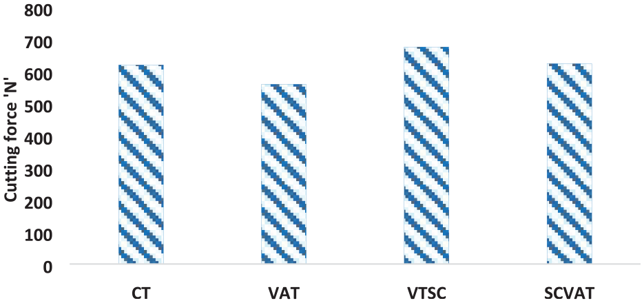
Comparison of cutting force in CT, VAT, VTSC, and SCVAT.
Although both the processes are ultrasonic assisted, SCVAT recorded higher cutting forces than VAT due to effective cooling provided by high pressure CO2 gas. The impingement of CO2 at the cutting zone reduces the tool work interface temperature and enhances the strain hardening effect. Thus the material strength increases thereby increasing the cutting force. This is also the reason for the highest cutting force in VTSC. This phenomenon of cooling induced strain hardening is counteracted by the high impact energy of tool due to ultrasonic assistance in SCVAT. The impact energy is sufficient to reach the ultimate strength of the workpiece material thus enabling easy chip removal and reducing the cutting force. 30 Thus the integration of vibration assistance and cooling not only reduced the cutting force in SCVAT but also minimizes the drawback of increasing cutting force with VTSC. The absence of cooling medium resulted in lower cutting forces in CT and VAT vis-a-vis its counterparts. In case of CT, thermal softening due to high temperatures allowed easy material removal resulting in low cutting force and the presence of ultrasonic assistance in VAT further enhanced the process, as explained earlier. From the above discussion, one can conclude that SCVAT has the capability to reduce cutting forces even when cooling is applied. Thus the advantage of cooling can be utilized without increasing the cutting force.
Surface roughness
Surface roughness is always regarded as the key deciding factor for component quality. The fatigue life of the component also improves with surface finish. Hence, the efficacy of a machining process in making a quality and reliable machined component can be evaluated based on surface roughness. The average surface roughness achieved under similar cutting conditions in all the processes is shown in Figure 8. It is clear that CT produces a rough surface whereas the proposed SCVAT promises a better surface finish. The improvement in SCVAT is 65.97%, 56.91%, and 8.80% when compared with CT, VAT, and VTSC respectively. This is attributed to the cumulative effect of high pressure CO2 cooling and intermittent cutting in SCVAT. The flow of coolant into the cutting zone during the non-cutting time of tool, reduces tool wear due to effective heat dissipation. The use of CO2 gas as coolant reduces friction coefficient at the cutting zone. The newly formed surface is also protected from flowing chips because of better chip disposal due to the combined effect of intermittent cutting and pressurized coolant flow. The lower conductive heat transfer (between tool and work) due to intermittent cutting mechanism and higher convective heat transfer (tool-work interface and surroundings) by the application of CO2 gas collectively reduces cutting temperature as discussed earlier. In addition, the impact energy due to ultrasonic assistance to the tool suppresses the unevenness of the machined surface. The absence of cooling medium in VAT and ultrasonic assistance in VTSC resulted in inferior surface finish relative to SCVAT. This illustrates the benefits derived from the integration of ultrasonic assistance and cooling techniques. It can also be understood that the role of cooling medium is predominant in attaining a better surface finish. Lack of cooling medium, increased temperatures and accumulation of chips at the cutting zone are reasons for poor surface finish in CT.
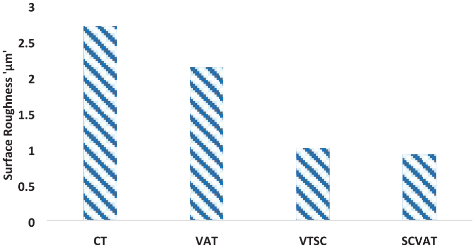
Comparison of surface roughness in CT, VAT, VTSC, and SCVAT.
Tool wear
The tool wear has a profound influence on machining quality, economics and sustainability. In this work, tool wear studies were conducted while machining Ti alloy using CT, VAT, VTSC, and SCVAT. The machining was done at constant cutting conditions for 15 min with a fresh tool for each process. Maximum flank wear was considered for evaluation of tool wear and depicted in Figure 9. It was identified from the analysis that tool wear is maximum in CT while it was the lowest for SCVAT. SCVAT boasts integrated benefits of its constituent technologies for reducing tool wear. Application of coolant at the cutting zone reduced the temperature which also happens in case of VTSC. However, in SCVAT intermittent cutting simultaneously reduces conductive heat transfer to the tool and enhances convective heat transfer from the cutting zone thanks to the effective flow of coolant into the tool-work interface. Hence, the tool is protected from being exposed to excessive heat, minimizing tool wear in the process. Moreover, as no coolant is used in VAT, convective heat transfer is not so influential even though conductive heat transfer to tool is lowered due to interrupted cutting. This led to more tool wear in VAT compared to SCVAT.
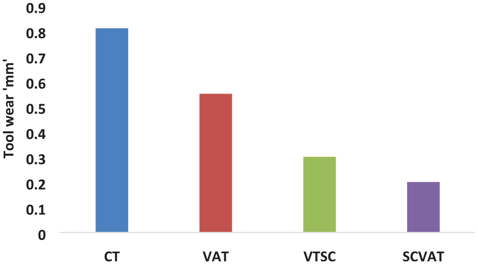
Comparison of tool wear in CT, VAT, VTSC, and SCVAT.
Figure 10(a) to (d), showcases the SEM micrographs that decipher the underlying mechanism causing tool wear. The magnification is adjusted in such a way that the flank wear is clearly visible at different machining conditions. The abrasion wear is predominant in causing the tool wear in all the processes with varying severities. The abrasive marks and micro grooves on the tool flank face are observed in CT, VAT, and VTSC whereas they are meager for SCVAT. The grooves are intense in CT due to the occurrence of high temperature at the cutting zone and high conductivity of heat by the tool as evident from Figure 10(a). This makes the tool softer and prone to erosion under prolonged cutting. In VAT, though conductive heat transfer is minimized to the tool due to intermittent cutting, absence of cooling medium led to local welding of chips to the cutting edge as shown in Figure 10(b). Therefore, one can conclude that adhesive wear mechanism cannot be neglected. However, the grooves are shallower compared to CT. Improved heat transfer in case of VTSC and SCVAT reduced the effect of abrasion and adhesion, as is apparent from Figure 10(c) and (d). In SCVAT the wear grooves are minimal compared to VTSC due to reduced conductive heat transfer (to the tool) and improved convective heat transfer (from the cutting zone to cooling medium). These together reduce tool temperature and hence tool wear. It is also worth noting that no significant adhesion of chips was observed when cooling was applied. In addition to reducing the temperature, the high pressure coolant quickly removed the chips from the cutting zone. As a result, chip contact duration was shortened and so was the formation of chip weldment on the tool. From this analysis, it can be concluded that tool wear is minimal for SCVAT with abrasive wear as its governing mechanism.
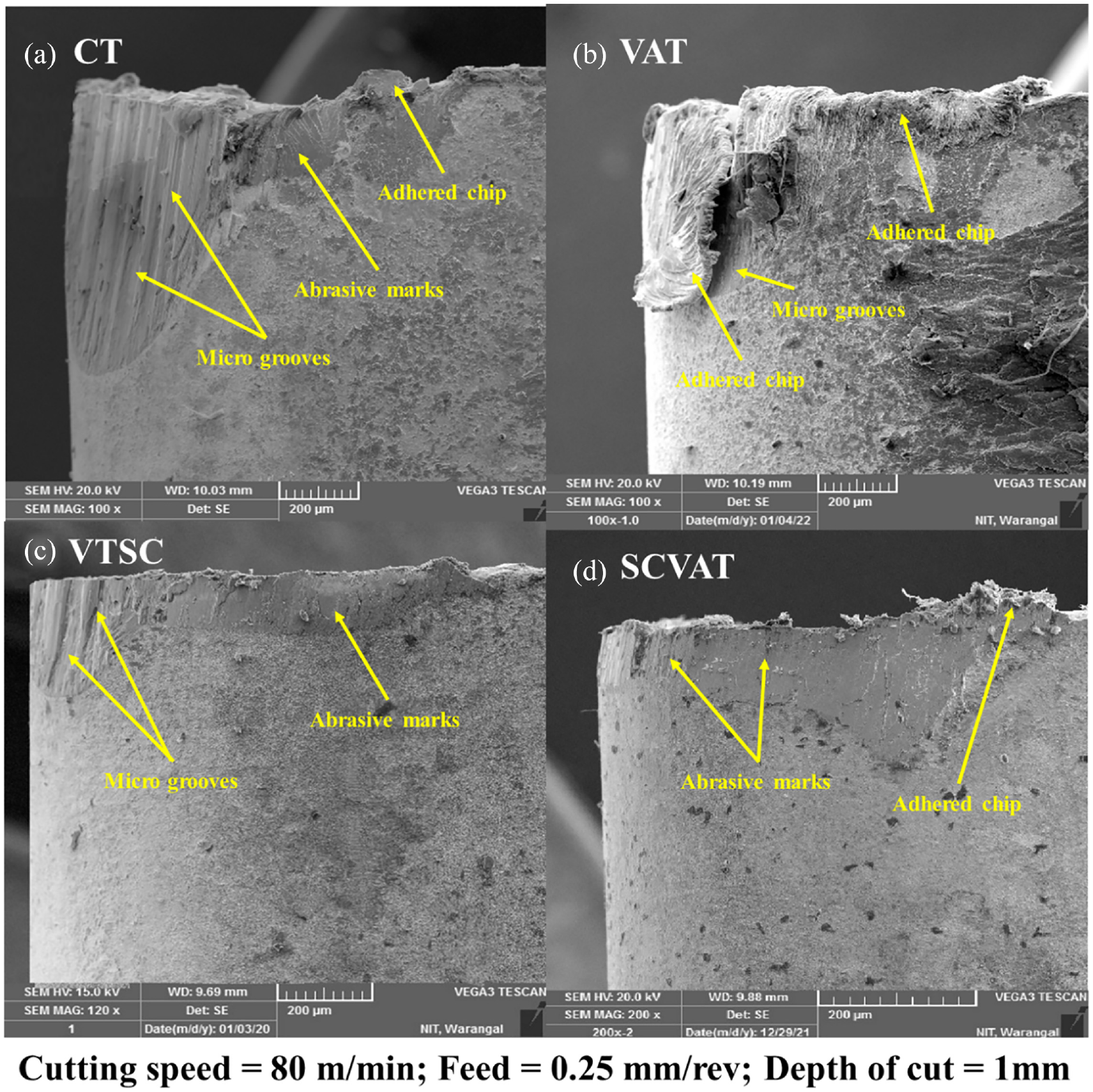
Worn surface of tool: (a) CT, (b) VAT, (c) VTSC, and (d) SCVAT.
Surface residual stress
The surface residual stresses generated due to machining is a crucial parameter that determines the fatigue life of the component. Residual stresses are governed by mechanical and thermal phenomena. In this study, SCVAT was evaluated in terms of surface residual stress and compared with other processes. The surface residual stress variation for all techniques is shown in Figure 11. It can be observed that surface residual stresses were compressive in nature in VAT, VTSC, and SCVAT while being tensile in case of CT. The compressive surface residual stress in SCVAT was due to better heat dissipation because of coolant application as well as vibration assistance. The impingement of cold CO2 gas at the cutting zone minimizes heat localization due to improved convective heat transfer. Thus the thermal phenomenon is inhibited and reduces the formation of tensile residual stresses. This is also the reason for compressive residual stress in VTSC. On the other hand, the presence of intermittent cutting nature in SCVAT led to the formation of compressive residual stresses due to vibro-impacts of the cutting tool which is also the reason behind generation of compressive residual stresses in VAT. 50 Thus the integration of cooling medium with ultrasonic assistance together inhibited the formation of tensile residual stresses and imparted compressive residual stresses in SCVAT, which are supposed to increase the fatigue life of the component. 51 However, lower magnitude of stress was recorded in SCVAT when compared to VTSC though the nature of stresses was the same. This is because of mechanical load being more dominant in VTSC as evident from the higher magnitude of cutting forces. As discussed earlier, higher cutting forces are counteracted by SCVAT with the addition of ultrasonic assistance. Hence the mechanical load was not so dominant in SCVAT when compared to VTSC, thereby leading to lower residual stresses in the former. The lack of proper heat dissipation results in high heat accumulation causing tensile residual stresses in CT. Though compressive residual stresses are formed in VAT due to the presence of ultrasonic assistance, 52 the heat dissipation is not so effective as in case of VTSC and SCVAT, thereby reducing the magnitude of stresses. It is noteworthy that SCVAT performed better than VAT in terms of magnitude and CT in terms of nature of stress.
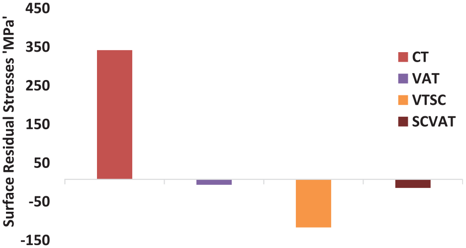
Comparison of surface residual stress in CT, VAT, VTSC, and SCVAT.
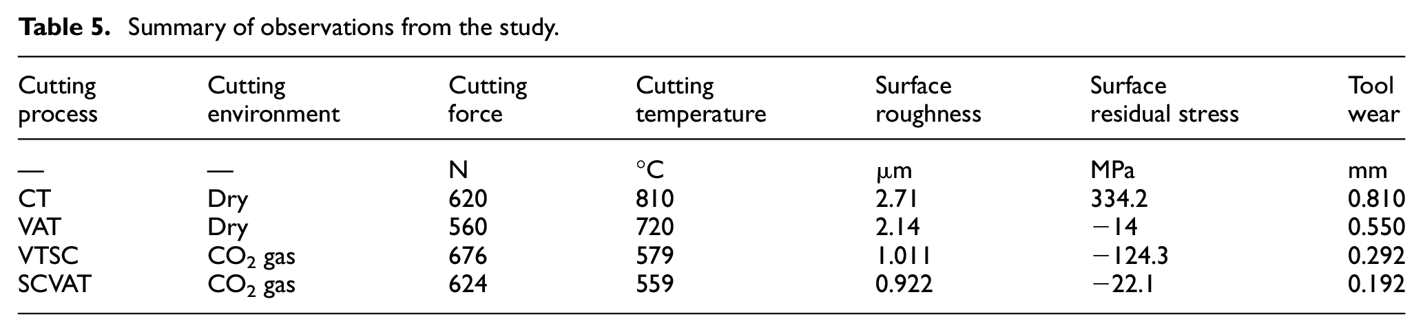
The overall findings of the study are summarized as follows and presented in Table 5.
Summary of observations from the study.
Conclusions
The work focused on the design of SCVAT set up and performance evaluation of the same in Ti alloy machining. The following conclusions are drawn from the study:
The cutting temperature is lowest in SCVAT followed by VTSC, VAT, and CT. The reduction in SCVAT is due to the penetration of low temperature CO2 gas in the cutting zone during the non-cutting time. When compared with CT, VAT, and VTSC, SCVAT achieved temperature reduction by 30.98%, 28.80%, and 4%.
High quality surface was achieved in SCVAT compared to other processes. The improvement was 65.97% than CT, 56.91% than VAT and 8.80% than VTSC. This is due to the combined effect of impact energy of the tool, reduced cutting temperatures by cooling, intermittent cutting action, and also reduced tool wear.
Tool wear was minimum in SCVAT compared to all other processes. This is because of the effective heat transfer due to cooling associated with intermittent cutting mechanism.
Compressive surface residual stresses were recorded in SCVAT, VTSC, and VAT while tensile stresses were observed in CT. VTSC recorded highest compressive residual stress followed by SCVAT and VAT. The reduction in magnitude of compressive residual stresses in SCVAT in relation to VTSC was due to the domination of mechanical load in the latter. The enhanced heat transfer in SCVAT resulted in compressive residual stress but reduced mechanical load because of the vibration assistance led to decreased magnitude of the same compared to VTSC.
The cutting forces reduced in SCVAT in comparison with VTSC by 7.69% but increased by 10% than VAT and 0.6% than CT. The cutting forces also increased in VTSC compared to CT and VAT, which is attributed to the strain hardening effect due to rapid cooling. However, in SCVAT, the intermittent cutting nature counteracted the aforementioned effect and reduced the cutting forces close to CT, thereby delivering the advantage of integrated techniques.
The overall study evidently showed the advantage of integrated hybrid technique, SCVAT in improving the machinability of Ti alloy, suggesting it as a superior alternative in machining the alloy. A detailed study and choice of better cutting, cooling, and vibration conditions can further enhance the process capabilities, making it a more sustainable and efficient technique.
Scope for future work
This work can be extended further as mentioned below:
The effect of machining, vibration, and cooling parameters on machining responses can be explored for better understanding of SCVAT process.
Finite element simulation of SCVAT can be carried out to study the combined effect of cooling and vibration on thermomechanical loading and residual stresses.
Parametric optimization and sustainability aspects of the SCVAT can be done for possible application in the industry.
Footnotes
Declaration of Conflicting Interests
The author(s) declared no potential conflicts of interest with respect to the research, authorship, and/or publication of this article.
Funding
The author(s) received no financial support for the research, authorship, and/or publication of this article.