
Abstract
The use of an argon–water medium rather than air–water medium is proposed to increase the material removal rate (MRR) and decrease surface oxide production for short electric arc machining. To provide a more stable discharge state during high-temperature processing, this approach uses argon to reduce the production of highly resistant refractory materials (e.g. titanium oxide). For short-arc machining of Ti6Al4V titanium alloy, the effects of the voltage, milling depth, electrode speed and gas flow rate on the MRR, relative electrode loss rate and surface roughness were compared for air–water and argon–water mixtures. It was discovered that the milling depth and voltage had the greatest impact on the MRR, voltage and electrode rotational speed had the greatest impact on the relative tool electrode wear rate (REWR), and voltage had the greatest impact on the surface roughness. In contrast to the air–water mixture, the MRR with the argon–water working medium was as high as 9391 mm3/min, with a 13% improvement in MRR, as well as a smooth and flat surface of the machined workpiece. Nevertheless, the REWR increased to 2.46% and the surface roughness was at least 432 μm with the argon–water medium, increasing by 59 μm compared with the air–water medium. Moreover, the addition of argon reduced the types of surface compound on the workpiece and decreased the residual stress defects, including the recast layer, microcracks and holes.
Introduction
Titanium alloys are widely used in aerospace and marine chemical fields for such applications as pressure vessel shells for marine pipelines, deep submersibles and aerospace engine parts owing to their exceptional qualities, such as low density, high strength and corrosion resistance.1–3 The Ti6Al4V titanium alloy, which is an α + β two-phase alloy and has good all-around performance, is the most popular titanium alloy, accounting for more than 50% of titanium alloy production. 4 Nevertheless, in conventional machining, its high chemical activity and poor thermal conductivity are usually prone to react with CO2, N2 and O2 to produce a hard surface layer that intensifies tool wear. Furthermore, cutting heat tends to collect in the area where the tool and workpiece make contact, aggravating tool wear and increasing the likelihood of chips adhering to the machined surface. 5 As a noncontact machining process, electric discharge machining (EDM) provides a solution for the production of Ti6Al4V titanium alloy by applying a pulsed voltage between the electrode and the workpiece to generate heat to remove the material. 6
Conventional EDM has a low material removal rate (MRR), which severely restricts its use. Researchers have proposed improvements to EDM to address this issue. For example, Jafferson et al. 7 enhanced the machining environment to improve the machining efficiency by applying a magnetic field to the workpiece during EDM to encourage the discharge of etched particles from the machining gap. Eyercioglu et al. 8 discovered that a compromise solution is needed when choosing the EDM parameters (i.e. discharge current, pulse-on time and pulse-off time) to maintain machining stability (melt evaporation and debris removal). Owing to the stability maintained during machining, the dimensional accuracy was improved and better machining results were obtained within a reasonable machining time. According to Prakash et al. 9 to improve the machining speed and surface integrity of machined features, a suitable combination of tool and workpiece materials is required. Zhao et al. 10 explored the use of mixed powder EDM at low pulse widths, resulting in more discharges, thereby enhancing EDM machining efficiency. Rouniyar and Shandilya 11 utilised a combination of a magnetic field and fine powder in a dielectric fluid. The peak current was found to have the greatest influence on the MRR and tool wear, followed by the pulse-on time, powder concentration and magnetic field. The peak current, pulse-on time, and pulse-off time increased with increasing peak current, MRR and tool wear rate (TWR). Cao et al. 12 suggested EDM ablative machining using an internally injected aerosol (a mixture of oxygen and water) to improve the MRR using the reaction between the material and oxygen to generate chemical energy as the machining energy for material removal. Nevertheless, the machining efficiency of these improved EDM processes requires further improvement. Electric arc machining (EAM), an evolutionary branch of EDM, has significantly enhanced the MRR using high-energy-state arc melting of materials. For instance, Zhou et al. 13 used the rotary motion of a tool to generate an intermittent arc to remove material, called ‘short electric arc machining’ (SEAM) and the maximum MRR can reach 10,000–15,000 mm3/min. Later, Chen et al. 14 discovered that negative-polarity processing yielded poorer surface quality and higher rates of material removal. Wang et al. 15 suggested EDM/EAM composite machining using a power supply composed of a high-voltage pulse and low-voltage DC, and the maximum MRR of machining titanium alloy was more than 20,000 mm3/min. Zhao et al. 16 suggested blast corrosion arc machining using porous electrodes, which indicates the advantages of efficient machining of large features, and Kou et al. 17 suggested DC motion arc machining based on electrode rotation and hydrodynamic coupled arc breaking, which significantly enhanced the MRR. For studying short arcs, Zhu et al. 18 proposed a hybrid power system composed of a pulsed DC power supply. The results showed that, as the combined pulse voltage increased, the MRR increased and the TWR decreased, whereas the combined pulse voltage had less effect on the surface roughness (Rz) with a maximum MRR of 4721.63 mm3/min.
The working medium is crucial for EDM and EAM by creating a dielectric environment, compressing the discharge channel, and removing ionisation. Jeswani used water as the EDM medium and obtained a higher processing efficiency than when using kerosene. 19 Shen et al. 20 suggested near-dry EDM and acquired a higher MRR and lower surface roughness. Yadav et al. 21 investigated how oxygen mixing affected the machining process and discovered that oxygen addition accelerated material melting and improved the MRR.
In this study, the air medium commonly used in SEAM was replaced with argon to improve the processing performance of SEAM further. In contrast to the conventional SEAM processing method, the arc maintenance time is longer under an argon–water condition, thereby improving the MRR. The surface oxide deposit of the workpiece was reduced by the argon–water process, leaving a smooth, flat surface with fewer cracks. In this study, the effects of argon–water and air–water mixed media on DC SEAM processing were compared, and the MRR, relative electrode wear rate (REWR), discharge characteristics and surface properties of Ti6Al4V titanium alloy processed by argon and air at different discharge energies were investigated.
Electric-field simulation analysis
Electric-field model
As illustrated in Figure 1, an electric-field simulation model for SEAM was established and divided into meshes. According to the actual processing size, the simplified model was separated into three sections: electrode, dielectric and workpiece. The electrode gap was set to 0.1 mm and the local mesh was encrypted for the area. The workpiece was assumed to be fully oxidised; the material was titanium dioxide when the dielectric was air and it was made of pure titanium when the dielectric was argon. An electrostatic field was used for the setup with a fixed voltage of 0 V at the electrode and 30 V at the workpiece.
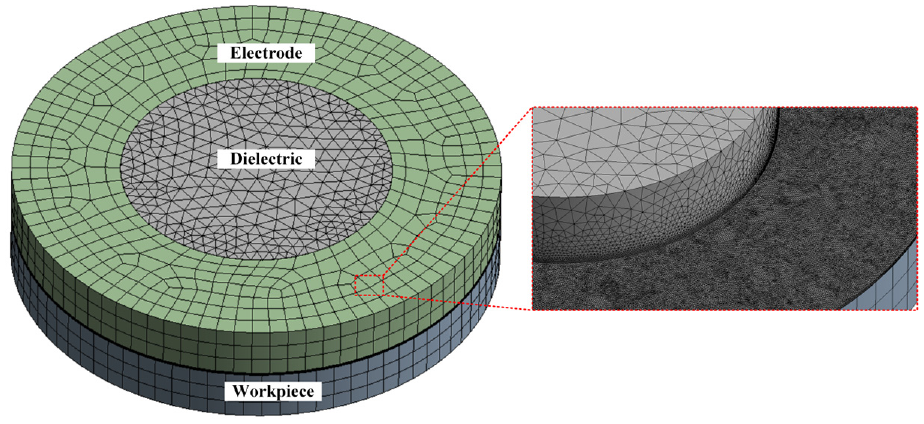
Geometric model diagram.
Simulation results and analysis
The electric-field simulation of the cross-sectional electric-field intensity cloud is shown in Figure 2. As the figure shows, the electric-field intensity distribution in the two gases processed was narrow and the electrode corner had the highest local electric-field intensity. This is because the gases have very high insulating properties. In theory, the two gases belong to completely insulating materials, so the electric-field intensity of the breakdown of the two gases does not vary too much and the breakdown process of the arc only occurs in the dielectric, so the electric-field intensity near the workpiece material fails to change significantly.
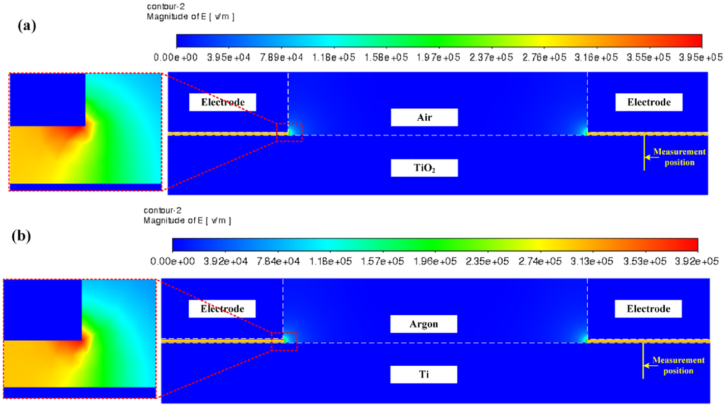
Electric-field intensity distribution cloud map: (a) air machined and (b) argon machined.
Because the production of oxidation on the metal substrate during both gas processes is their primary distinguishing characteristic, the oxidised workpiece material can influence future current conduction. Thus, the current density distribution at the workpiece surface was measured according to the measurement position illustrated in Figure 2. The current density distribution curves of the two gases on pure titanium and titanium oxide are shown in Figure 3 at the same point. As illustrated in the figure, the current density on pure titanium is significantly greater than that on titanium dioxide produced by processing with air and the current density decreases from the surface of the workpiece to the interior. Because the conductivity of titanium dioxide is significantly lower than that of pure titanium, processing with air is likely to produce a high-resistance refractory material, which inhibits current conduction and may affect the smooth removal of material, reduce the MRR and also change the discharge state of the gap.
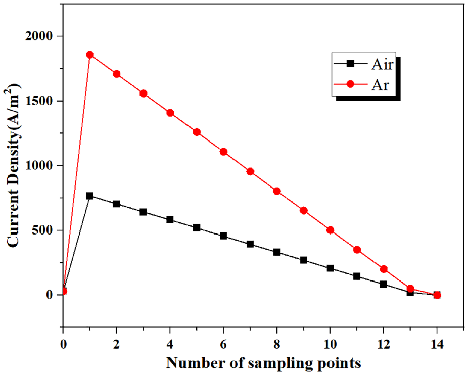
Current density distribution curve.
Experimental details
Experimental setup and principle
Figure 4 shows a schematic diagram of the SEAM system. The workpiece and electrode both receive DC voltage from the power supply. The motor drives the spindle to rotate and move at a high speed and moves the workpiece along the X- and Y-axes. The gas–liquid mixture is forced into the machining gap through the inner hole of the electrode and the outer punch nozzle. As shown in Figure 5, when the electrode is fed to the workpiece, the strong electric field pierces the medium to produce a plasma discharge channel and the charged particles in the channel move in a directional manner, hitting the electrode surface and workpiece. This concentrated heat causes the workpiece to melt and vaporise, creating vaporisation, melting, and heat-affected zones in the machining area. Subsequently, the high-speed flowing working medium continues to rush into the machining gap to remove the melting products and heat to achieve efficient material removal.
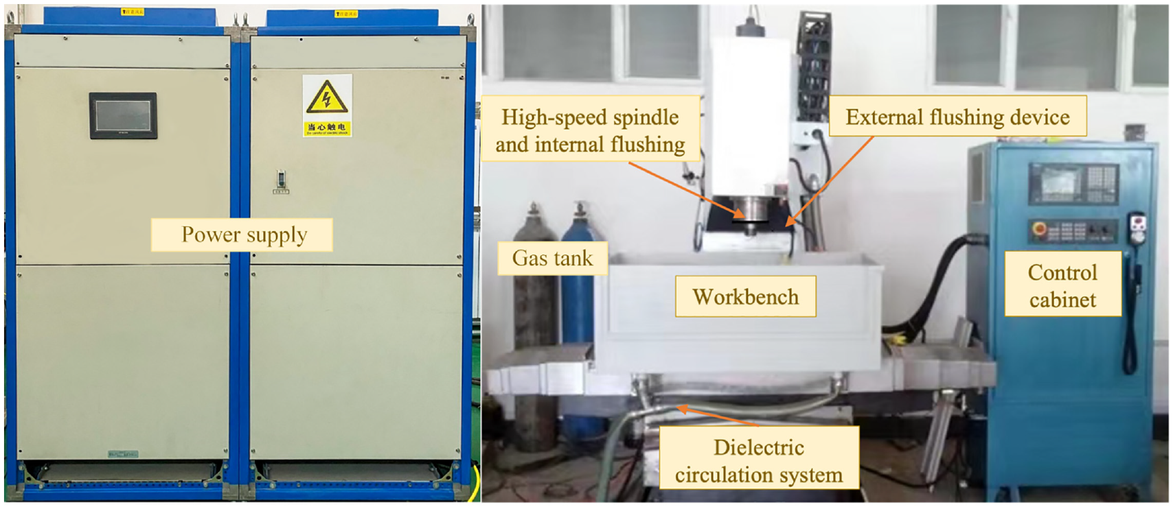
SEAM system.
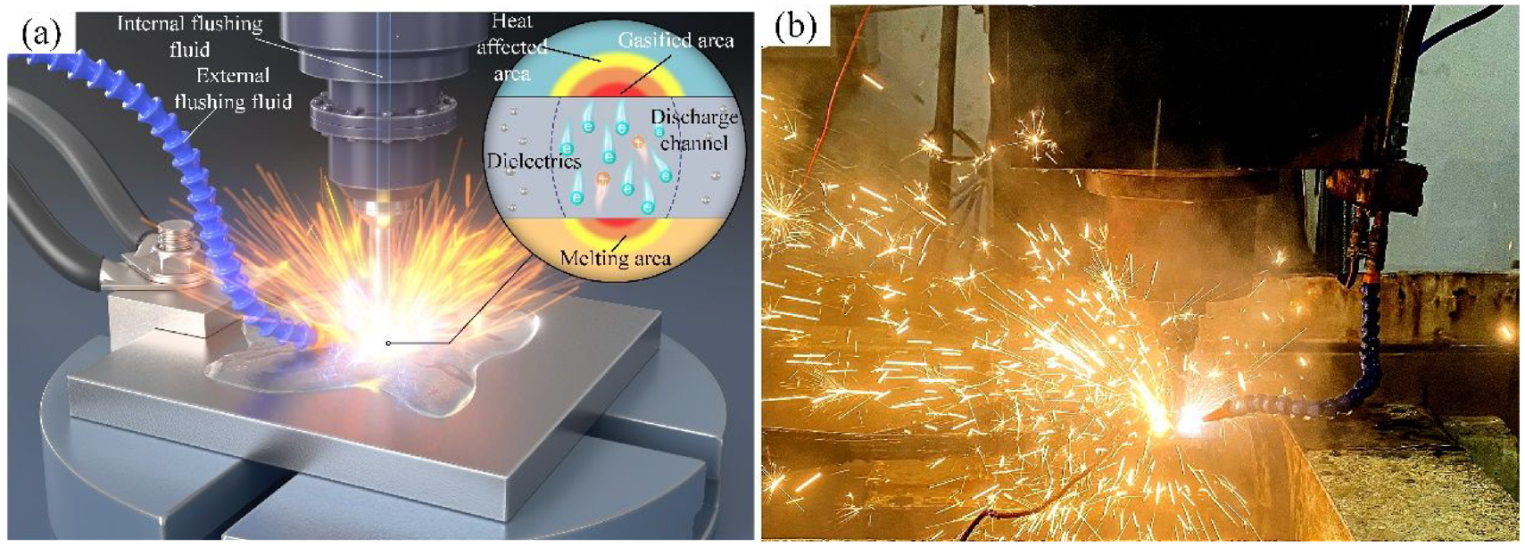
Schematic diagram of SEAM principle and field machining diagram: (a) schematic diagram of SEAM and (b) field machining diagram.
Experimental procedure
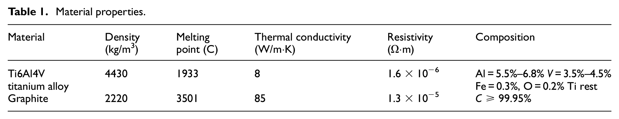
With a DC power supply acting as the energy source, SEAM experiments were performed to achieve the highest MRR. The electrode was a hollow cylindrical graphite electrode with an outer diameter of 18 mm and an inner diameter of 6 mm, and the workpiece was a Ti6Al4V titanium alloy specimen with dimensions of 30 mm × 30 mm × 8 mm. Its material properties are listed in Table 1.
Material properties.
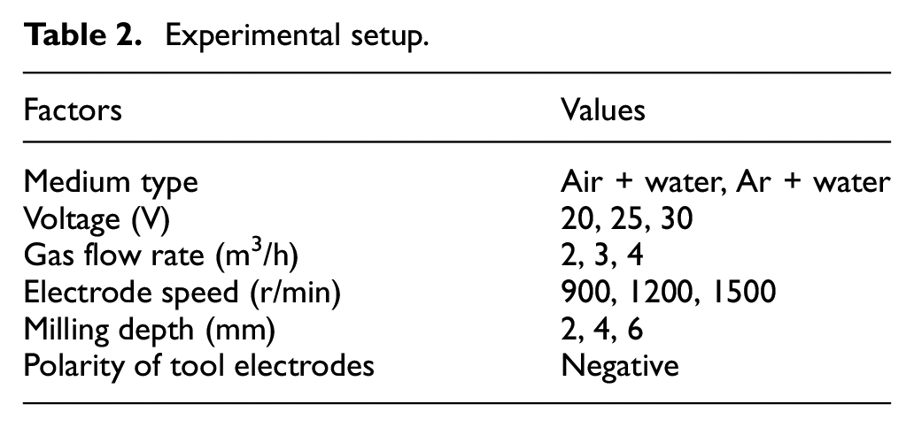
In the experiments, the machining performance of compressed air–water and argon–water as working media were contrasted at various voltages and the MRR, REWR, discharge characteristics, workpiece surface morphology, element migration changes, surface roughness and cross-sectional morphology were examined under various medium machining conditions. The specific process parameters used in the experiments are listed in Table 2.
Experimental setup.
Experimental measurements
The MRR and REWR are calculated as follows.
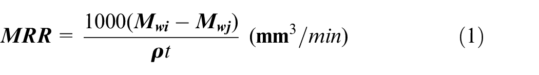
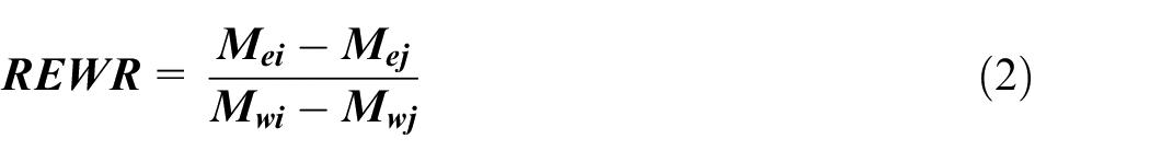
where
During the SEAM process, the DEWESoft SIRIUSI series multichannel data acquisition system was utilised to gather, analyse and record the gap voltage and gap current. A digital microscope (VHX-7000) was used to observe the three-dimensional shape of the workpiece surface and measure the surface roughness. The workpiece was cut into 5 mm × 5 mm × 6 mm samples using a DK7720 EDM machine and the microscopic surface morphologies of the samples were observed. In addition, an elemental analysis through energy-dispersive X-ray spectroscopy (EDS) of the surface was performed using a scanning electron microscopy (SEM; JSM-6460). The cross section of the workpiece was observed using scanning confocal microscope, and the microhardness was measured using a WOLPERT-401-MVD microhardness tester and electron backscatter diffraction (EBSD; EDAX-TSL). A precision balance with an accuracy of 0.1 mg was used to measure the mass of the workpiece and electrode before and after machining.
Results and discussion
Material removal rate
Figure 6 contrasts the MRRs of argon–water and air–water media for different parameters. As the figure shows, different gases escape with different electron energies, thereby producing different colours of light. For example, the rare gas argon emits a dazzling blue–violet glow when it is ionised. As the voltage increases, the discharge energy rises, the volume and speed of material melting increase, and the MRR of argon machining is higher than that of air machining. In air, 78% of nitrogen and 21% of oxygen exist. Because titanium alloy has high chemical activity, it easily reacts with nitrogen and oxygen to generate high-resistance refractory material. 22 This is also because of the high discharge energy during SEAM. Although the use of argon gas machining can prevent the oxidation and nitridation of titanium alloy, the large thermal stress is prone to microcracking, making it easier for these gases to enter the interior of the titanium alloy and cause nitridation and oxidation of titanium, further impeding the efficient removal of the material. Moreover, as Figure 6 shows, the parameters with the greatest influence on the MRR are the milling depth and voltage. The electrode speed and gas flow rate do not significantly influence the MRR, the dielectric strength of argon is lower than that of air and the discharge gap is larger. Furthermore, the etching products are more easily discharged from the gap, leading to a better discharge condition and, therefore, a higher MRR. High voltages make this more noticeable, and, at 30 V, machining with argon has an MRR that is roughly 31.76% higher than that of machining with air.
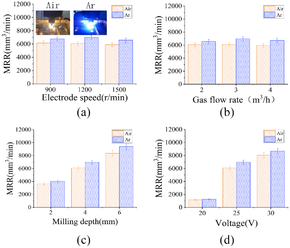
Comparison of argon and air MRRs with different parameters.
Relative electrode wear rate
The REWR for treatments with air–water and argon–water with different parameters are shown in Figure 7. The electrode speed and voltage have the greatest effects on the REWR. In addition, processing with argon generally results in a larger REWR than processing with air, which may be related to the increase in MRR. The REWR for machining with both gases reaches its minimum value at 25 V. Because graphite is soft, at low voltage, the discharge energy is inadequate and the electrode is prone to contact and wear during feeding into the workpiece; at high voltages, however, too high a discharge energy partially melts the electrode. Although the melting point of graphite is as high as 3501°C, the theoretical temperature at a high discharge energy is as much as 10,000°C 23 and the wear of the electrode increases. Higher electrode speeds are more likely to break the arc, leading to unstable burning and ultimately insufficient energy input, which wears out the electrode and workpiece and increases the electrode loss. 24 Nevertheless, as Figure 7(c) shows, negative motor loss occurs at a milling depth of 6 mm, which is because the energy input is larger and more concentrated under the argon–water medium, and the waste chips are not discharged from the gap in time and adhere to the surface of the electrode, leading to negative motor pole loss. Although air has a higher dielectric strength than most other materials and is less sensitive to changes in the discharge gap when employed as a dielectric, there is not much difference between the REWRs of air at 30–25 V.
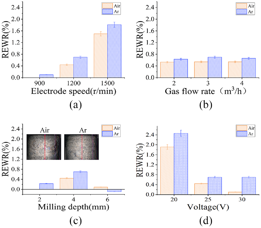
Argon and air REWR comparison for different parameters.
The morphologies of the electrodes created using argon and air at 25 V are compared in Figure 8. Both electrodes exhibit pits from the discharge recorrosion on the side of the electrode, but the pits on the surface of the argon-machined electrode are deeper and wider than those of the air-machined electrode, indicating that the discharge energy is higher and more concentrated under argon machining. Nevertheless, more bumps can be seen on the surface of the air-machined electrode, which might have developed because the titanium alloy was partially bonded to the electrode surface after removal and the discharge gap of the air-machined electrode may be smaller than that of the argon-machined electrode.
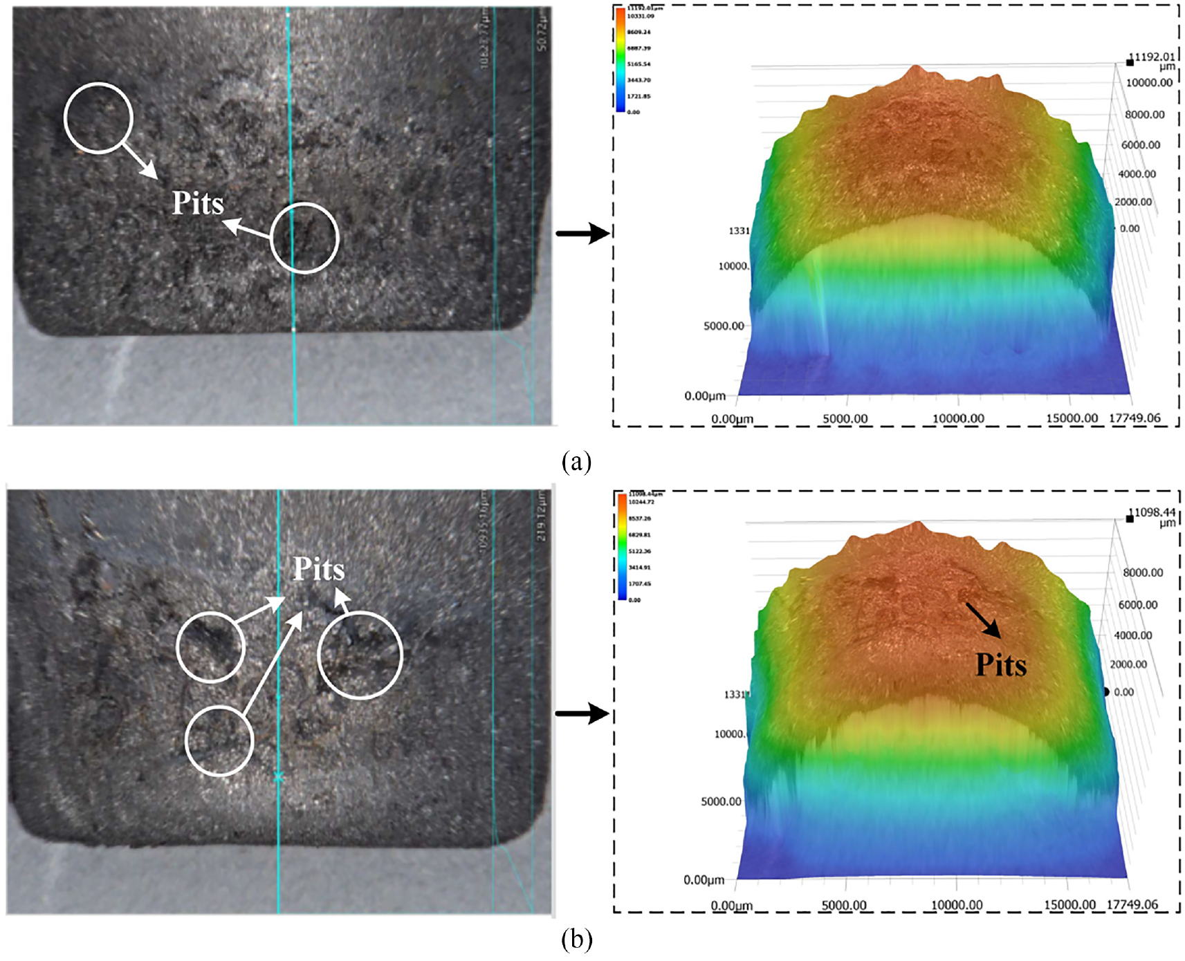
Electrode wear morphologies: (a) air machining and (b) argon machining.
SEM was used to magnify the electrode surface and view the microscopic details of the electrode surface to observe the electrode surfaces under both gas machining conditions in more detail. As illustrated in Figure 9, denser micropits existed on the surface of the electrode machined using argon, whereas the surface machined under air not only had pits but also many melt drops stained on the electrode surface. The staining of melt drops on the surface suggests that the gap flow field condition is poorer with air machining, indicating that the machining gap is smaller, which verifies the findings of Kong et al. Because the gas pressure is the same for both gases, they have the same flow field entrance conditions. 25
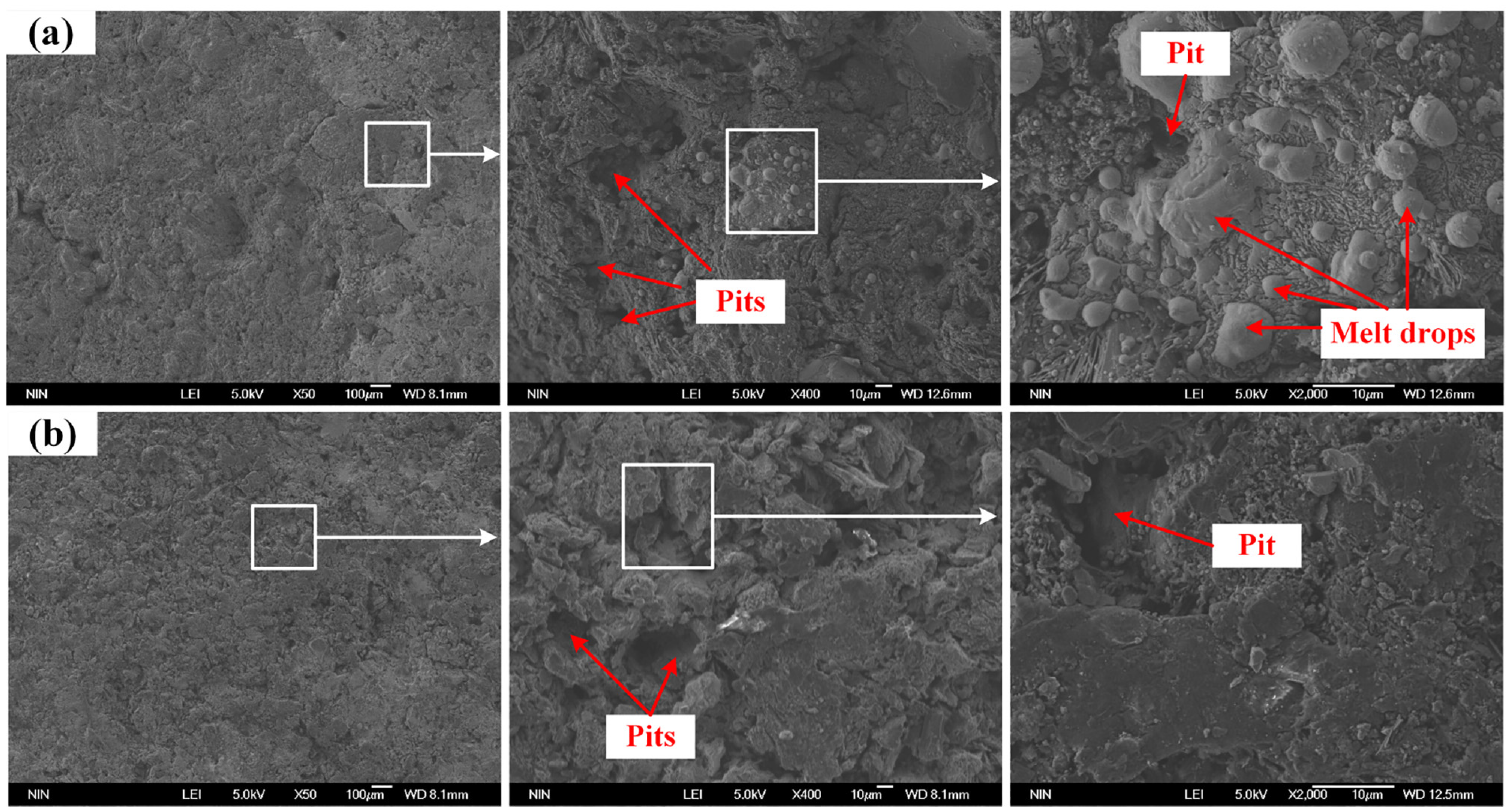
Electrode wear microscopic features: (a) air machining and (b) argon machining.
Surface roughness analysis
Figure 10 illustrates how the machining factors affect argon–water and air–water media. The surface roughness Ry progressively increases with voltage and decreases with increasing electrode speed. In contrast, the surface roughness is mostly unaffected by the gas flow rate and milling depth. However, regardless of the parameters, all argon–water condition Ry values are larger than those of the air–water condition. This is because the argon–water condition produces more concentrated energy discharge, the more serious erosion of the workpiece surface produces a larger discharge pit, and finally a larger Ry is produced. For traditional EDM, Ry can reach 8.5 μm. 26 Therefore, under certain circumstances, SEAM is ideal for rough machining or semiprecision machining.
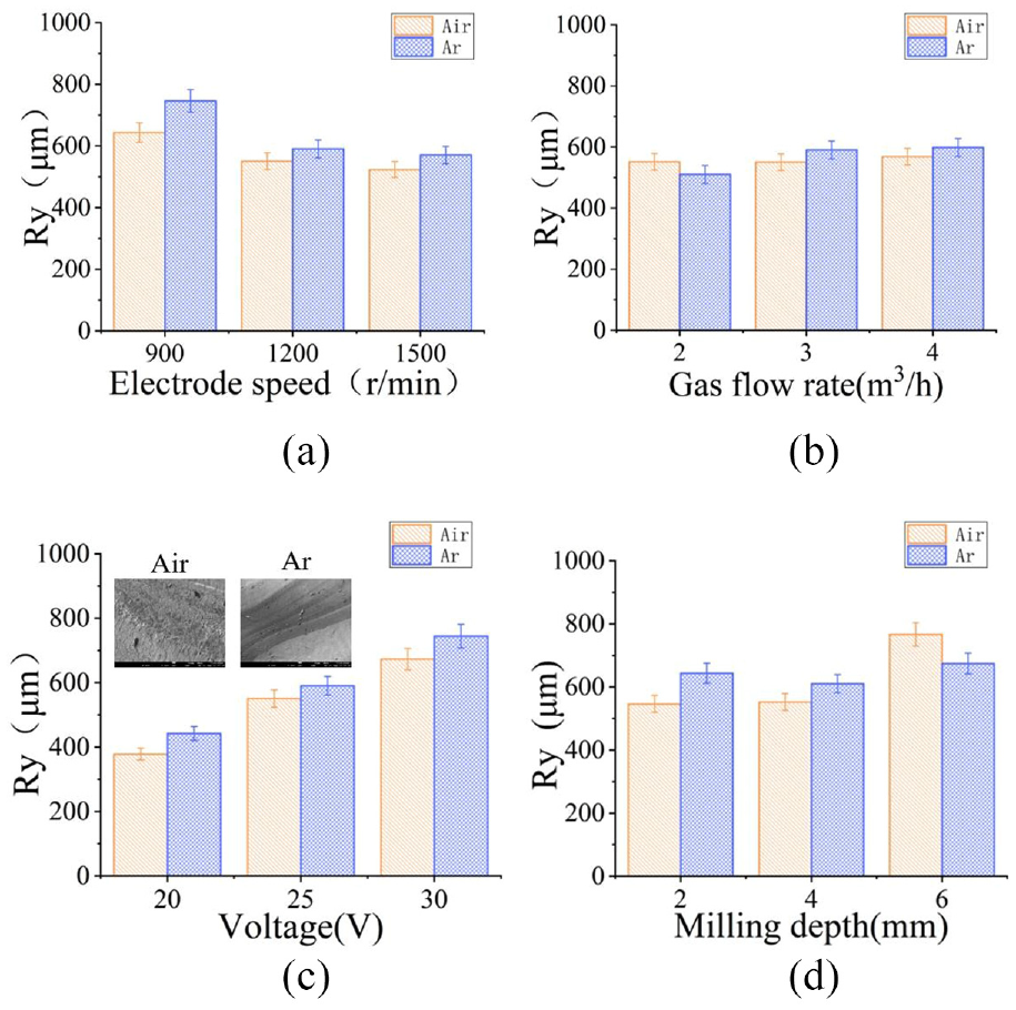
Argon and air Ry comparison for different parameters.
Discharge characteristics
Figure 11 shows the gap voltage–current waveforms for air and argon machining under 25-V conditions. The peak current in the machining with air is low, with a maximum current of only 610 A, whereas the peak current in the machining with argon can reach 1503 A. This difference is caused by the dielectric properties of the gas, which are weaker in argon than in air, making it easier for the dielectric to break down and form an arc. At the same time, there is an intensively low current of approximately 50–60 A in the air-machining waveform, which might be caused by the small discharge gap and the secondary discharge that occurs between the etched particles and the workpiece or electrode. In argon machining, this phenomenon is essentially nonexistent. Moreover, a continuous arc with a long maintenance time is found during the machining process. Even though the arc exists for a long time, no short circuit with continued high current occurs, indicating the existence of a stable discharge gap during this machining period, which facilitates the MRR.
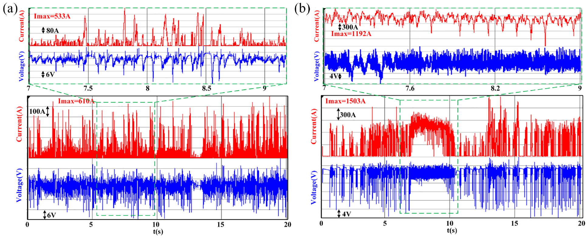
Voltage and current waveforms: (a) air machining and (b) argon machining.
Three-dimensional morphology of the workpiece
The two surfaces in Figure 12 are machined surfaces obtained with the same voltage of 25 V, electrode speed of 1200 r/min, milling depth of 4 mm, and gas flow rate of 3 m3/h, with argon–water (Figure 12(b)) and air–water (Figure 12(a)) media. The surface roughness of the workpiece machined by air and argon increases linearly with the increase in voltage, and the surface roughness of the workpiece machined by argon is always higher than that of the workpiece machined by air. Craters and bumps on the surface machined by argon were always found. It is possible that a long continuous arc during argon machining produces such bar craters combined with the discharge waveform in Figure 11, squeezing the metal near the melt pool to bulge upward when the material melts while forming bar bumps. As the voltage increases, the arc is more difficult to pull off, leading to an increase in both the length and the width of the crater.
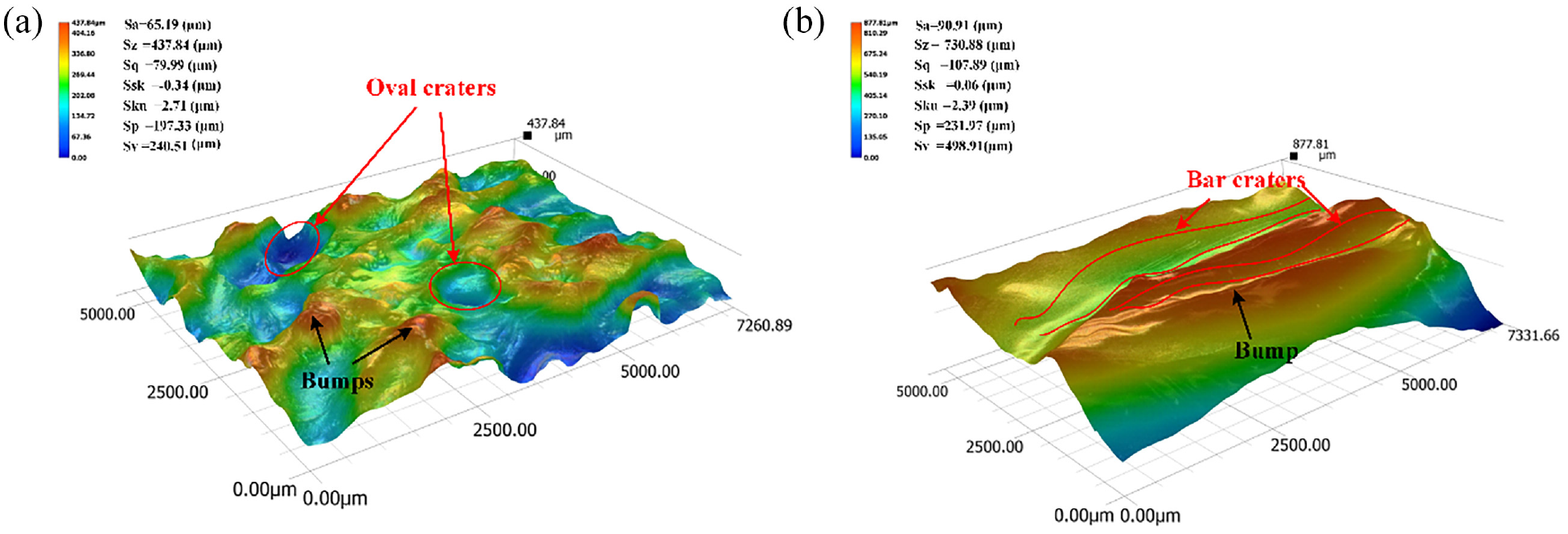
Three-dimensional morphologies in different media: (a) air machining and (b) argon machining.
Oval craters and bumps were always found on the surface of the workpiece machined in air, whereas, at 30 V, bar craters appeared on the surface of the workpiece. Moreover, there were always oval pits on the surface machined in air because air has a higher dielectric strength and is more easily deionised. Moreover, because of the high-resistance insoluble material formed during machining, it was more difficult for the next discharge to occur, and the depth and width of the pits increased, whereas the surface roughness decreased significantly. At 30 V, oval pits and bar pits both appeared because the discharge energy was enhanced and the plasma channel was more difficult to extinguish, resulting in both a continuous arc and a single arc.
Surface morphology and elemental analysis of the workpiece
The microscopic morphology of the workpiece surface is shown in Figure 13. The surface of the air-machined workpiece has a significant amount of blue-purple titanium oxide coating, as the macroscopic shape of the surface shows. A magnified observation of this area reveals an obvious recast layer on the surface. Owing to residual stresses, as well as the presence of sparse holes, form when oxygen from the air enters the recast layer during the metal resolidification process, the recast layer contains cracks. In contrast, the workpiece surface after argon machining is essentially free from peroxidation. Due to the generation of less high-resistance titanium oxide film, the microscopic morphology of the workpiece surface is also extremely smooth. This smoothness makes it easier for the etching products to discharge from the interstices and makes the discharge process more stable. EDS tests of the two surface machining methods reveal a 37% reduction of oxygen elements on the surface of the workpiece machined with argon compared with those machined with air, which reduces the number of chemical reactions that take place. Because titanium is extremely susceptible to oxidation, even argon-machined surfaces can generate additional oxide films owing to the involvement of ambient air in the reaction.
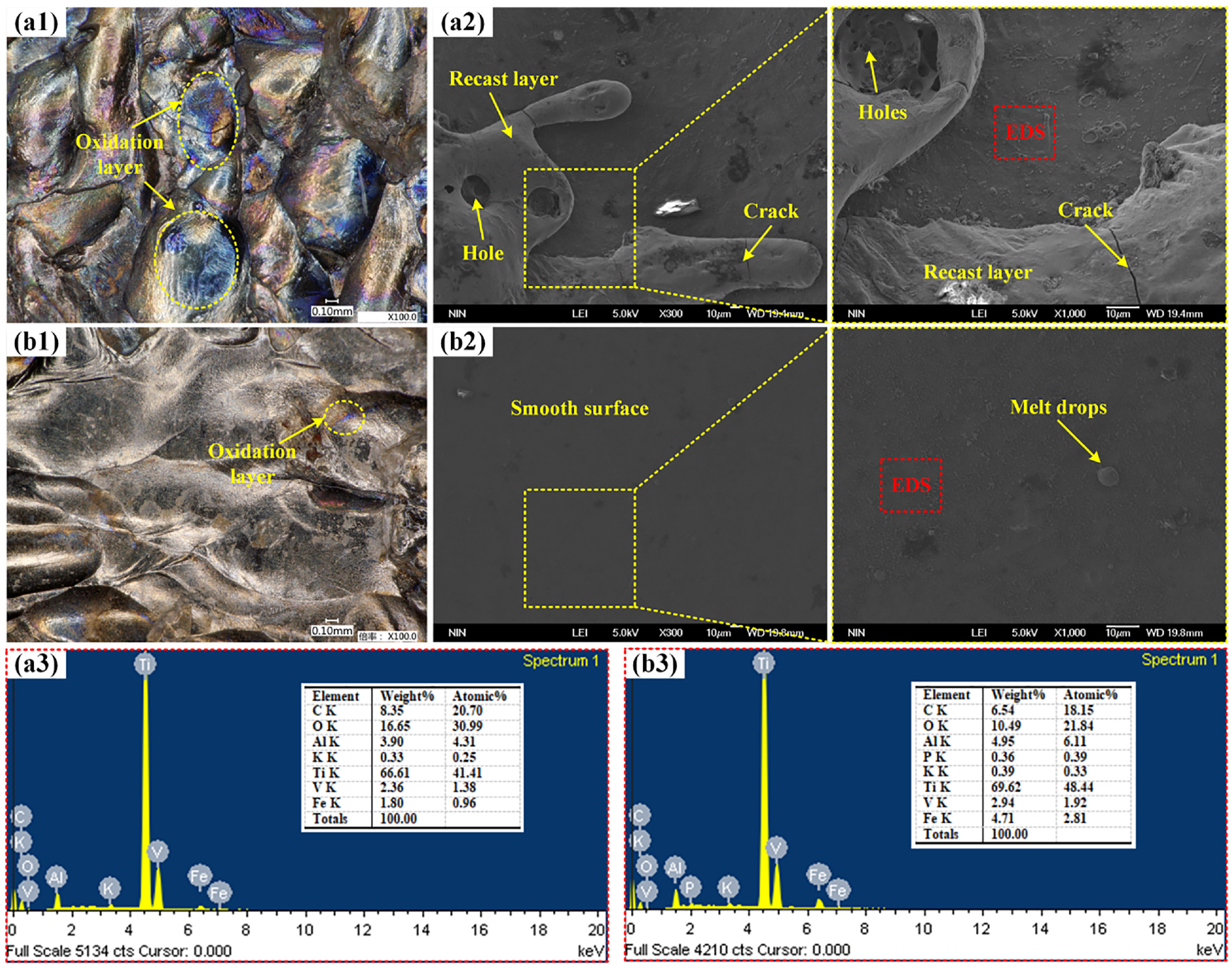
Microscopic morphology of the workpiece surface and elemental analysis: (a) air machining and (b) argon machining.
To observe the elemental distribution on the workpiece surface, EDS surface scan analysis was performed on a local area of the workpiece surface. The outcomes are displayed in Figure 14. The most extensive distribution of the workpiece surface machined by both gases was still that of the titanium matrix element. Nevertheless, the surface of the workpiece machined with argon inhibited the occurrence of oxidation reactions, generating fewer oxide layers and exposing more of the base material, which has a 13.87% higher titanium content than that of the workpiece machined with air. Only the titanium in the metallic base material has a higher oxygen content than that of the surface machined in air, which was as much as 26.1%. The entire surface exhibited elemental oxygen. In contrast, only localised areas of the workpiece surface machined with argon have elemental oxygen, effectively inhibiting the oxidation reaction during machining. Furthermore, small amounts of nitrogen are found on the air-machined surface. The titanium undergoing oxidation and also the nitrides produce high-hardness titanium nitride. Distinct compounds have different physical and chemical characteristics. When they condense after melting, large residual stresses are created inside the recast layer, so microcracks, such as those illustrated in Figure 13(a2), are observed. Machining with argon reduces the variety of metal compounds; therefore, there are fewer residual stress defects on the surface of the workpiece.
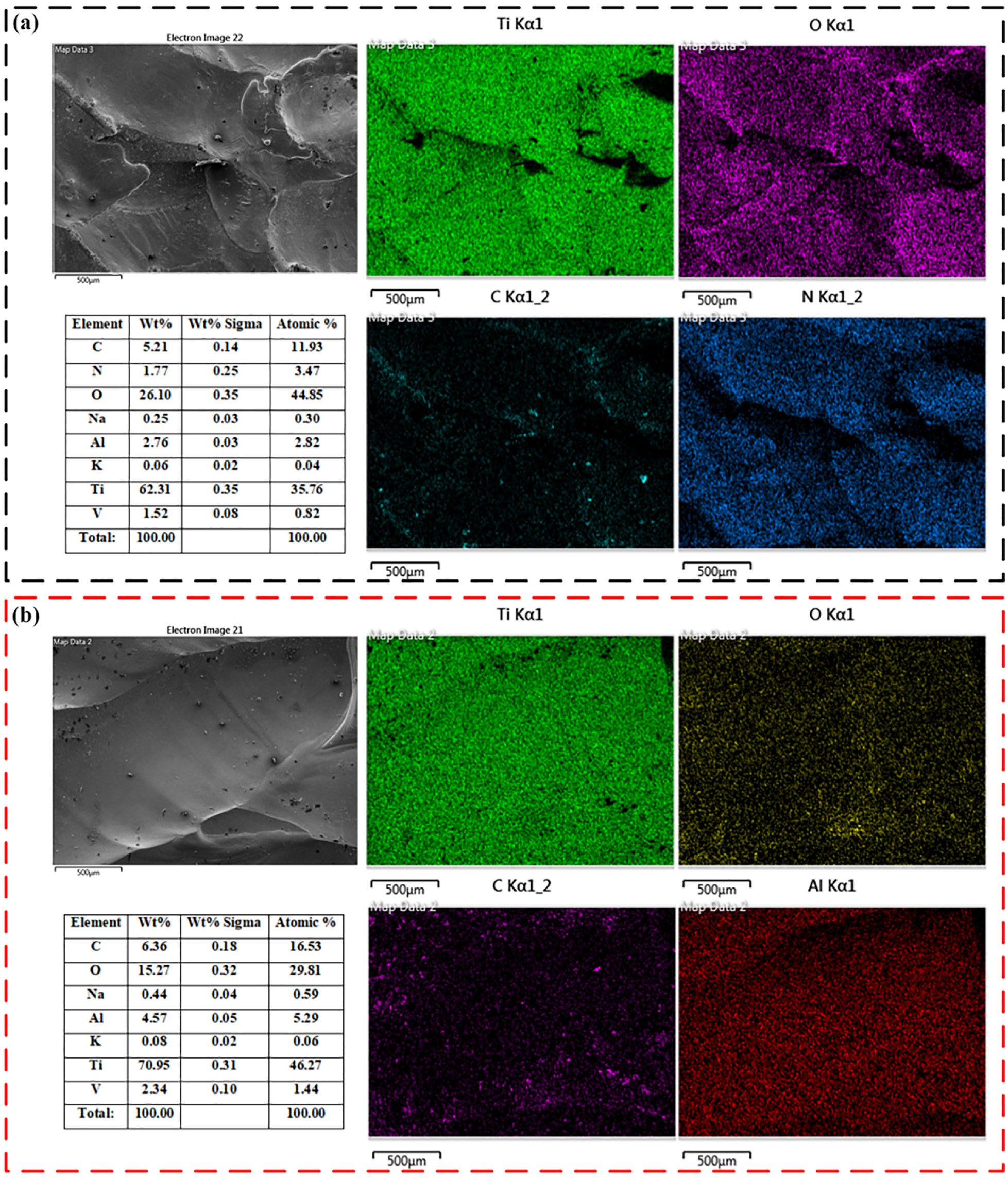
EDS surface scan analysis: (a) air machining and (b) argon machining.
Cross-sectional morphology
A corrosion solution was prepared with hydrofluoric acid, nitric acid and water and the workpiece was cut, sampled, ground, polished and etched under 25-V machining conditions. The cross section of the workpiece was observed under a metallographic microscope. As illustrated in Figure 15, the surface of the workpiece machined with both gases exhibited delamination of the recast and heat-affected layers, which occurs frequently in the electrical discharge cutting of surfaces. 27 The surface machined under air produced a high-resistance refractory material (titanium oxide, etc.), which resulted in an unstable discharge state and was prone to secondary discharge and local overheating. Therefore, the recast layer was thicker and unevenly distributed, which caused an increase in the thickness and uneven distribution of the heat-affected layer. In argon machining, when the discharge is more stable, the resulting recast layer is thinner and the thickness of the heat-affected layer tends to be consistent because of uniform heating. The connection between the recast layer, heat-affected layer, and substrate in Figure 12(a) and (b) was used for EBSD grain analysis and the transition phenomenon of grains was discovered. The gradual refinement of the grain degree from the metal matrix to the recast layer occurs because the workpiece material is melted by heat, and part of the melted material has not yet flowed out of the discharge gap. In addition, the water–gas mixing medium quickly solidifies this part of the molten material, which is again bonded to the surface to form the recast layer. Therefore, the formation of the recast layer involves the process of grain recrystallisation, and the larger subcooling causes rapid grain refinement. 28 Melt drops and microcracks, which drastically impair the properties of the material, are frequently present in the recast layer. The heat-affected layer is produced by the refinement of the matrix grains because of the heat during machining or heat transfer from the recast layer to the substrate. The recast and heat-affected layers have different material properties from the substrate, which might result in part failure in production. Compared with workpieces machined using air, the thicknesses of the recast and heat-affected layers on the surface are reduced. The residual stress is measured from the material matrix along the workpiece surface, as illustrated in Figure 15(c) and (d). The figure shows that, because the recast layer processed by argon is thinner, the probability of microcracks is lower; thus, the residual stress is smaller. Because there is less heat build up, the residual stress in the heat-affected layer also decreases. With the effect of liquid filling, the good cooling effect makes the diffusion of heat energy does not affect the substrate, Therefore the residual stress on the substrate is almost flat.
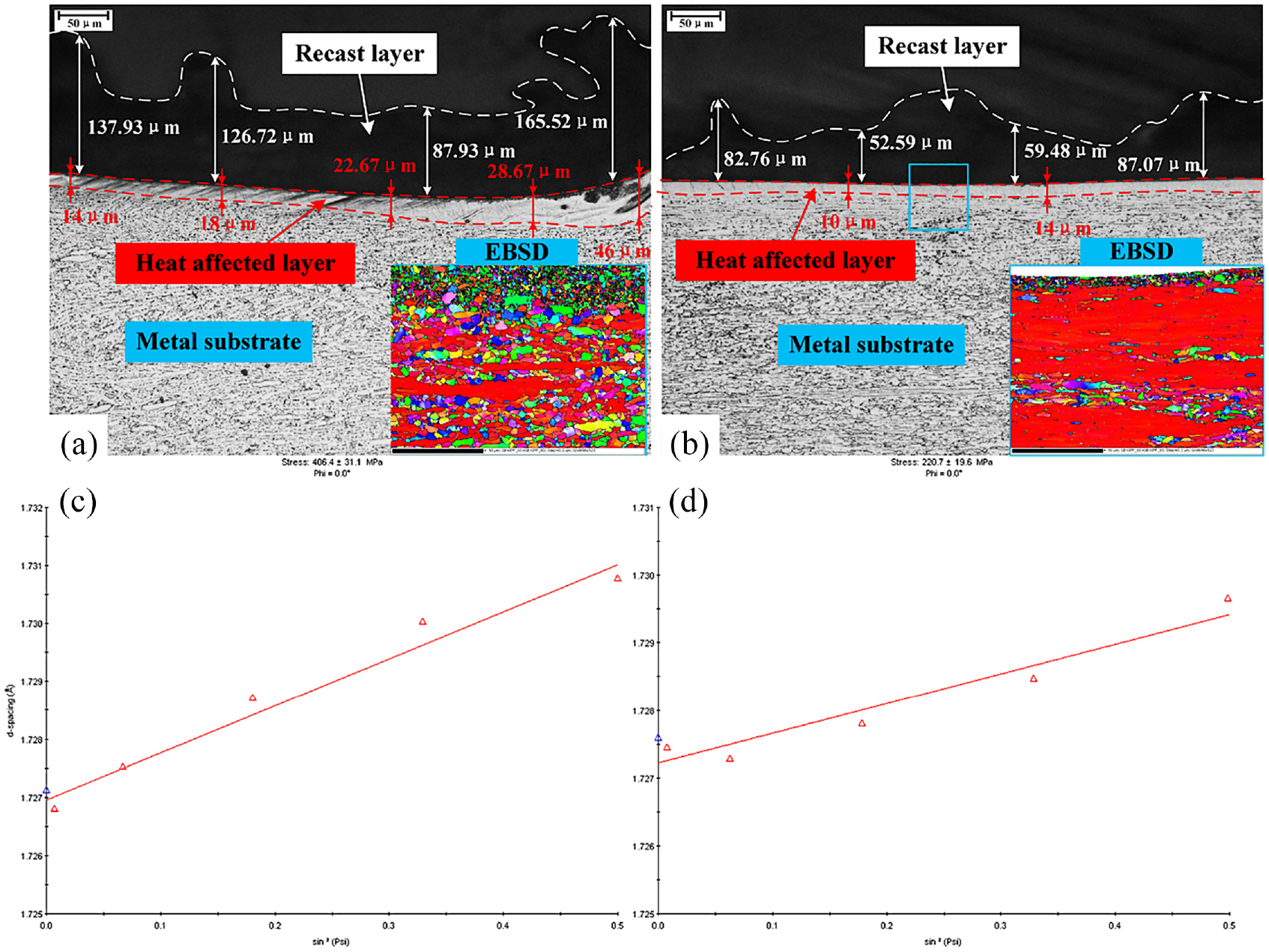
Cross-sectional morphology: (a and c) air machining and (b and d) argon machining.
Conclusions
The machining properties of Ti6Al4V titanium alloy machined with argon–water and air–water media were investigated experimentally. The MRR and electrode wear rates for machining with both gases at different voltages, rotational speeds, milling depths and gas flow rates were examined. The discharge characteristics and causes of electrode wear for machining with both gases were analysed. In addition, the surface morphologies of the machined workpieces were scrutinised and elemental analyses were performed. Finally, the cross-sectional morphology of the workpiece was studied and the causes of the defects were analysed. The following conclusions were drawn.
When cutting Ti6Al4V titanium alloy using an argon–water medium, the arc light is blue, and the material removal process is more violent than that of the air–water medium. The MRR of the argon–water process is higher than that of the air–water process in all cases and the MRR increases linearly with the increase in voltage and milling depth, whereas the MRR fails to change significantly with the change in electrode speed and gas flow rate. In the case of an argon–water medium, the main factors affecting the MRR are the milling depth and voltage, and the MRR for 6-mm-deep milling is approximately 12% higher than that of air–water machining.
Argon–water machining has a higher REWR than air–water machining. The proper machining voltage and milling depth lead to a stable discharge state, and the REWR is 0.16% higher at 25 V than that of air–water machining while ensuring a proper MRR.
When argon is the medium, the discharge energy is concentrated, making it easy to create a continuous arc for as much as 2 s, producing a wide discharge gap and resulting in the formation of long strip craters on the surface of the workpiece. When air is the medium, the discharge energy is lower, the discharge gap is smaller, and it is easy to cause a secondary discharge, resulting in the formation of oval craters on the surface of the workpiece.
The surface in air–water processing has a significant amount of blue–purple oxide film, producing more compounds and more microcracks and holes in the surface recast layer compared with the surface in argon processing, which has a small amount of oxide film, an oxygen element reduction of 6.16%, and a smoother, flatter surface.
The heat-affected and recast layers produced by argon processing are thinner than those created by air processing. The highest difference in the thickness of the heat-affected layer is 18 µm, and it is flatter, with a refinement tendency from the metal matrix to the surface of the recast layer.
Footnotes
CRediT authorship contribution statement
Yinan Zhao: Data curation, Methodology, Writing—Original draft preparation, Supervision. Jianping Zhou: Conceptualisation, Reviewing and Editing, Funding acquisition. Shengsheng Zhang: Formal analysis, Software. Xiangyu Dai: Experimental planning, Investigation. Ru Zhang: Experimental planning, Investigation. Zhouwei Liu: Data curation, Graphics Processing. Yan Xu: Validation.
Declaration of conflicting interests
The author(s) declared no potential conflicts of interest with respect to the research, authorship, and/or publication of this article.
Funding
The author(s) disclosed receipt of the following financial support for the research, authorship, and/or publication of this article: This work was supported by the Tianshan Innovation Team Project (Grant No. 2022D14002) and the Natural Science Foundation of China (Grant No. 51765063).