
Abstract
In this study, Ti6Al4V rods were butt-welded by rotary friction welding. The experimental results show that the weld quality, in terms of the tensile strength and hardness, decreases radially. Therefore, the radius of the welded parts that are viable for rotating friction welding is limited because the areas located far from the centre of the axis have poor mechanical properties. The parameter that impacts the tensile strength and microhardness the most during rotary friction welding of Ti6Al4V is the axial pressure, which includes the friction pressure and forging pressure. A high forging pressure produces fine, equiaxed, and recrystallized grain structures in the welded joint, resulting in a high tensile strength and microhardness. In addition, an increased forging pressure can be used in rotary friction welding to reduce the radial differences in the mechanical properties of the welded joints.
Introduction
Machined parts made by friction welding are becoming increasingly popular because the friction welding process has many advantages. Generally, structural components are fabricated from oversized ingots, forgings and extrusions. This fabrication method is costly because of the large amount of material that must be removed during the fabrication process. 1 Friction welding reduces the material required to make a component by joining small workpieces to produce a preform, which is subsequently machined to the desired dimensions. This method provides a substantial improvement to the buy-to-fly ratios, which significantly reduces manufacturing costs. This is especially true for titanium alloys since their cost is expensive. Titanium alloy Ti6Al4V is a lightweight, high-strength material that is widely used in the aerospace industry. Titanium alloys are also very important materials in other manufacturing fields, such as the automotive and medical device industries. In recent years, many reports on linear friction welding of Ti6Al4V have been presented.2–10 However, limited research has focused on the welding of Ti6Al4V by rotary friction welding. The rotary friction welding method was successfully applied to weld titanium alloys used in highly stressed gas turbine components, such as disc and spacer assemblies. 11 During the rotary friction welding process, the most important parameter is the input heat of the welding process.12–15 This heat input depends on the coefficient of friction, rotation speed and axial pressure. Therefore, the change in these parameters affects the quality of the welded joint. Many researchers have investigated the effect of friction welding parameters on the welded joint quality of stainless steel, 13 aluminium and copper,14,15 for example, to find the optimal friction welding parameters. However, the rotating friction welding process is complex and nonlinear, and it is strongly affected by the mechanical and thermal properties of welding materials. The welding optimal technology parameters for one material may not be suitable for another material. Therefore, a study of the influence of parameters on the welding quality of Ti6Al4V alloys is also needed. Ti6Al4V is an (α+β) alloy, and the cooling speed has a strong influence on the change in the phase structure. Pardhi 16 argued that the cooling rate is important because it changes the microstructure at the weld interface. When the axial pressure is high, the cooling speed is fast, and vice versa; when the rotation speed is fast, the cooling speed decreases. If the cooling process is fast, then the β phase is almost untransformed; therefore, the microstructure contains more phase β than any other phase. However, if the cooling process is slow, the β phase is transformed to the α phase, and the microstructure contains β, α and (α+β) phases. In the rotary friction welding process, the temperature rises at the weld surface during welding due to heat generated from friction, and the heat is then transferred to inside the components. Therefore, there is an uneven heat distribution within the workpiece in both the axial and radial directions. As the cooling process occurs, the rate of the temperature attenuation at these locations varies. The result of that process is that the microstructure in the welding zone differs significantly from the microstructure of the parent material, making the tensile strength and microhardness nonuniform inside welded joints in both the axial and radial directions. This paper presents an experimental investigation of the hardness and tensile strength at different positions in a rotating friction weld to find the weakest position in the welded joint. The influence of the welding parameters on the welded joint, such as the rotation speed, pressure and friction time, is also analysed in detail.
Experimental methods
The parts used in the rotary friction welding experiment of this study are cylindrical titanium rods composed of Ti6Al4V with diameters of 15 mm and lengths of 60 mm. The weld surfaces of the titanium rods are cleaned with acetone to eliminate any impurities and remove any oil, grease or dirt. During the rotary friction welding process, the workpieces are combined under load, and the technological process is done in three phases, as presented in Figures 1 and 2. During phase 1, one part is rotated against the other part, which is not moving, as shown in Figures 1(a) and 2(a). During phase 2, when the rotating part reaches a sufficient angular velocity, the fixed part is brought into contact with it by the axial force, which causes frictional heat to develop at the interface surface, as shown in Figures 1(b) and 2(b).
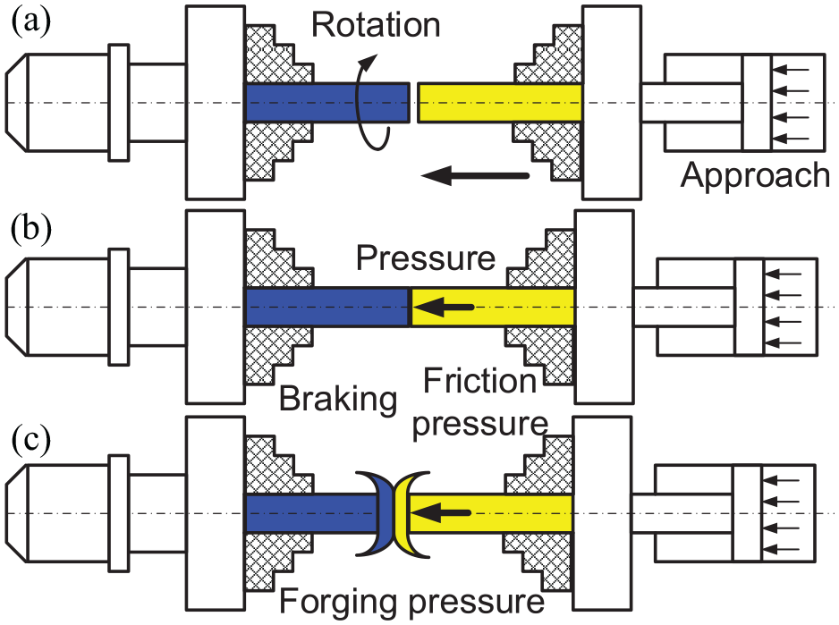
Schematic of the phases that occur during rotary friction welding: (a) friction phase, (b) braking phase, and (c) forging phase.
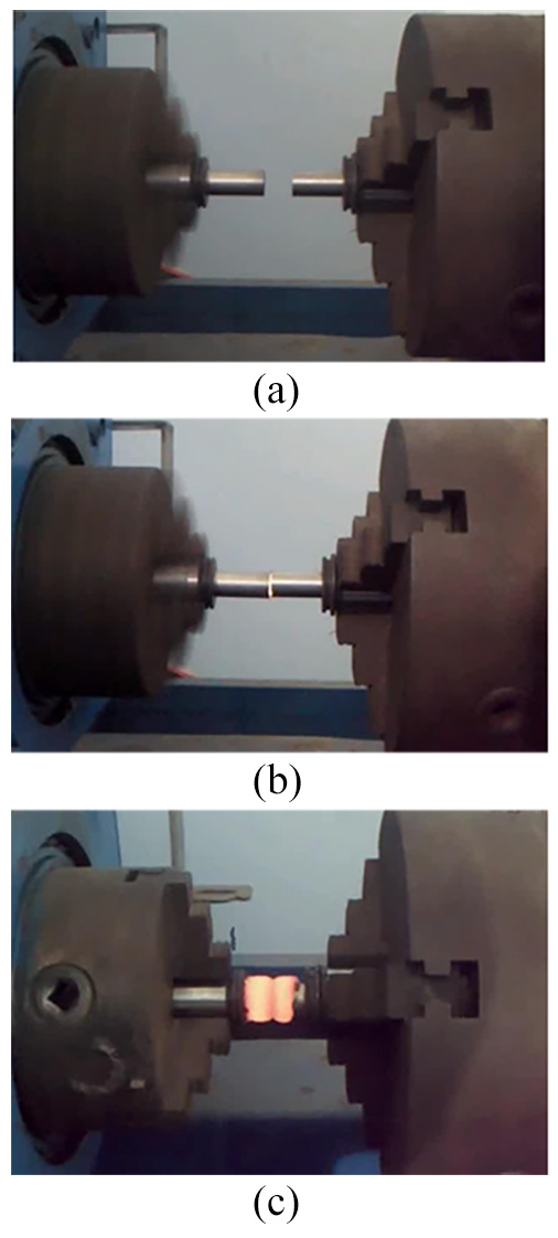
Actual phases that occur during rotary friction welding: (a) friction phase, (b) braking phase, and (c) forging phase.
During phase 3, when the joint area is sufficiently plastic as a result of an increase in the temperature, the rotation is stopped, and the forging force is increased to the maximum value to forge and consolidate the joint, as shown in Figures 1(c) and 2(c). At this point, extrusion of the plasticized material at the welding zone occurs, so a round collar shape is formed where the material has extruded. The heat generated by the welding process depends on the long velocity according to the equation as 12 :
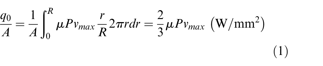
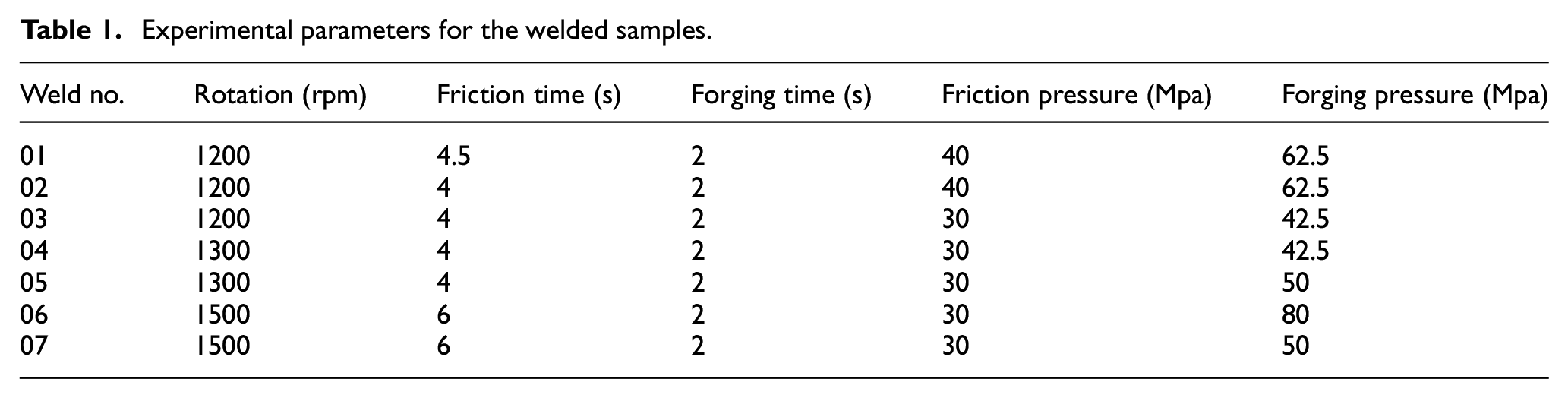
where q0 is the net power (W), μ is the friction coefficient, A is the cross section (mm2), P is the friction pressure (N/mm2), R is the surface radius (mm), and vmax (m/s) is the maximum long velocity at the outer edge. This input heat strongly influences the rotation speed and axial pressure. The temperature achieved at the weld interface depends on the input heat supplied during the friction welding process and friction time. To reduce the time required for the welding process and to increase productivity, a high input heat is chosen, and this value is theoretically calculated to be approximately 10 W/mm2, in which the friction coefficient is assumed to be 0.577. 12 By using equation (1) with the boundary condition for the input heat power above, literature recommendations16,20,23 and a large number of trials, the following rotary friction welding parameters are adopted for this study: the rotation speed is 1200–1500 (rpm), friction time is 4–6 (s), friction pressure is 30–40 (MPa), and forging pressure is 42.5–80 (MPa). The forging time is kept constant since this parameter does not significantly affect the weld quality. The details of the experimental parameters used in this study are shown in Table 1.
Experimental parameters for the welded samples.
To investigate the influence of the welding process on the mechanical properties of the welded joints, such as the tensile strength and microhardness, the welded joint quality was evaluated by the hierarchy slicing method in the radial direction, and the HV hardness of welded samples was measured at different positions in both the radial and axial directions, which is presented in detail in the next sections.
Results and discussion
Microstructure
Welded joint sample #03 is used as a representative to investigate the changes in microstructure in the friction welding joint. The microstructures of the welded joint are examined at points 1, 2, 3, 4 and 5, as shown in Figure 3(a).
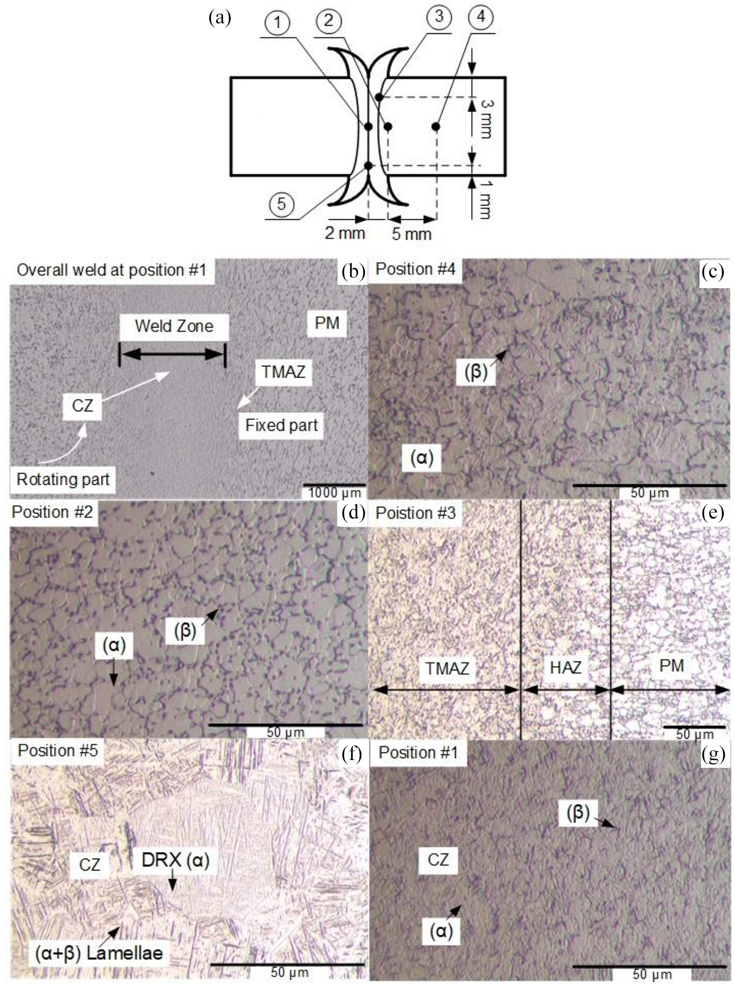
Optical micrographs at different positions of the weld joint in sample #3: (a) schematics of the examined points, (b) overall weld at position #1, (c) microstructure at position #4, (d) microstructure at position #2, (e) microstructure at position #3, (f) microstructure at position #5, and (g) microstructure at position #1.
Weld zone
As shown in Figure 3(b), the weld zone is located at the weld interface and is formed after the two weld parts are exposed to heat and pressure. During this process, one part is rotating, and the other part is resting. The material flow is observed as circumferential motion. The part of the material in the fixed part does not appear to flow. Figure 3(b) shows that the welded area is a continuous region, which indicates that rotating friction welding is successful for the Ti6Al4V alloy.
Parent metal
The microstructures at positions #2 and #4 are shown in Figure 3(d) and (c), respectively. The microstructures of these points are characterized by primary α and transformed β, and they are the same as the microstructure of the parent metal. This indicates that the region 2 mm from the welding interface is the parent metal region.
Centre zone
Figure 3(g) shows the microstructure at position #1, that is, the point located at the centre line of the welded joint. It can be observed that the microstructure of this point is primary α particles and secondary α lamellar phases in the β matrix. There has been a phase transition during the rotating friction welding process. Figure 3(f) shows the microstructure at position #5, which is very similar to the microstructure at position #1. However, at position #5, the microstructure contains many diamond-shaped α particles. This is probably due to the higher oxygen ratio at this location than that at other areas around the weld interface. The main reason for the formation of these small diamonds is that the cooling process occurs above the β phase transition temperature. When the friction phase is finished, the cooling process then occurs immediately, and the temperature is reduced in the welded area. Since the cooling process begins at different temperatures at different locations, it results in the formation of a biphasic microstructure in the friction welded Ti6Al4V alloys. In general, the grain size observed in this welded region is very fine because the temperature at the welding surface is above the β phase transition temperature, and recrystallization occurs during the cooling process.
Therefore, the CZ includes primary α and transformed β phases, as shown in Figure 3(f) and (g). Compared to that of the parent material, the microstructure in the CZ is significantly refined. It can be affirmed that dynamic recrystallization (DRX) has occurred in the CZ due to the significant plastic deformation and frictional heating during the rotating friction welding process. The microstructure change in the CZ is characterized by a fine lamellar structure (α+β), and the microstructure in the CZ can thus be defined as a bicrystal. The formation of a bicrystal microstructure in the CZ indicates that there are points in the welding region where the maximum temperature is below the β phase transition temperature. The β→ (α+β) transformation is created during the cooling phase of the rotating friction welding process, resulting in a smooth lamellar (α+β) structure due to the relatively high cooling rate. It is concluded that the recrystallized grain size of the weld zone at position #5 increases along the radial direction due to the rise of temperature.
The thermal mechanical affected zone
Figure 3(e) shows the microstructure at position #3. The area adjacent to the weld interface is referred to as the thermo-mechanically affected zone (TMAZ). In the TMAZ, as shown in Figure 3(e), the material flow is formed by the rotation of the two parts at the weld interface. The material flow in the circumference direction appears in the material from the rotating part. This flow is a typical result of rotating friction welding, and the material flows in a circular motion because one element is rotating and the other is stationary. This flow of material is not observed in the radial direction. This is explained by an increase in the temperature at the weld interface, which makes the material soft but does not melt it. The welding temperature has not increased to the melting point of the material. Two parts are thus welded in the solid state.
The heat-affected zone
The heat-affected zone is adjacent to the TMAZ, as shown in Figure 3(e). The microstructure of the HAZ seems to be almost identical to the microstructure of the parent material (PM).
Influence of the friction welding parameters on the mechanical properties of the welded joint
Influence of the friction time and rotation speed on the width of the welded joint
The width of welded joints is defined as the distance between the weld interface and the outermost edge of the HAZ. Vill 19 stated that the rotation speed is the least sensitive parameter on the width of a welded joint. This statement was also supported by Yates 20 regarding the inertial friction welding of Ti6Al4V. However, Da Silva, 21 Li et al. 22 and Bohme 23 found that if the rotation speed was low, then the welding width would be small. Pardhi 16 agreed that the width of weld joints is reduced when the axial pressure is increased, which means that additional materials are ejected from the weld joint in plastic form due to an increase in the pressure. However, an increase in the rotation speed increases the width of the weld joint. This study investigates the effect of friction time and rotation speed on the width of welded joints. The results in Figure 4 show that welded sample #02 with a friction time of 4 s has a joint width of 0.8 mm, and welded sample #01 with a friction time of 4.5 s has a width of 1.5 mm. This can be explained by the fact that an increase in the friction time also increases the heat transfer time in the part. This results in a wide area of heat-affected material.

The width of the friction welded joints.
Only the rotation speed is changed in welded samples #03 and #05. Namely, welded sample #05 is fabricated at 1300 rpm, and welded sample #03 is fabricated at 1200 rpm. The weld widths of the two samples are similar, and it can be concluded that the rotation speed does not significantly affect the weld width during rotary friction welding. This result is also consistent with the conclusions in Vill. 19
Influence of the forging pressure on the decrease in the weld width
To investigate the forging pressure impact on the weld width, two welded samples, # 06 and # 07, are studied and analysed. Both welded samples have the same parameters for rotation speed, friction pressure and friction time of 1500 rpm, 30 MPa and 6 s, respectively. Welded sample #06 is fabricated with a forging pressure of 80 MPa, and welded sample #07 is fabricated with a forging pressure of 50 MPa. The experimental results of the two welded samples are shown in Figure 5. It should be noted that the shapes of the welded joints during rotating friction welding are very different. During rotating friction welding, the heat at the centre of the welded joint is higher than that at the circumference because the heat loss at the circumference is rapid due to contact with the air. The welded joints therefore form curves, the welded area at the centre is narrow, and the weld width increases gradually at the edge of the part, as shown in Figure 5(a). This is different from that for linear friction welding, where the weld joint shape is quite regular in the horizontal direction due to the linear effect in contrast to the rotation.17,18
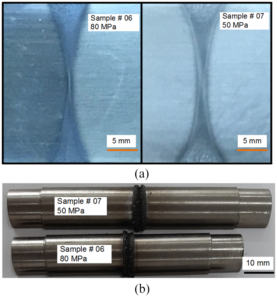
Influence of the forging pressure on the weld width: (a) the change in the width of the welded joints and (b) the change in the length of welded joints.
As shown in Figure 5(a), the welding pattern for sample # 06 is unsatisfactory because the weld width at the centre line is very small compared to that for the position at the outer edge of the weld. Weld #07 is fabricated with a decreased forging pressure, so it has an increased weld width. In general, an increased forging pressure causes the material to be ejected to the outer region, and therefore, the weld has a decreased weld width. When the forging pressure increases from 50 MPa to 80 MPa, the length of the welded part is reduced by approximately 8 mm, as shown in Figure 5(b). It can be concluded that if the forging pressure is increased, then both the width of the welded joint and length of the welded parts are reduced. This result is also consistent with the conclusions in Pardhi. 16
Influence of the technical parameters on the microhardness
The HV hardness of welded samples #1, #2, #3, #4, #5 and #6 are measured at different positions that are separated by 0.25 mm, as presented in Figure 6. The hardness measurement process is repeated at locations 1.5 mm from the main axis in the direction of the welding part diameter. The selection of the locations for hardness measurement as described above aims to examine the different hardness levels in both the axial and radial directions of the welding part. The Vickers hardness distributions of the welds at the centre line are measured and presented in Figure 7. Compared to the 310–340 HV microhardness of the Ti6Al4V parent material, the hardness of the weld area increases at approximately ± 0.75 mm around the weld interface.
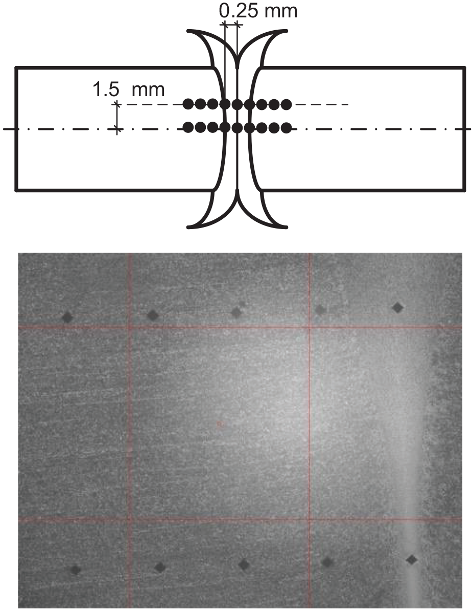
Locations used for the measurement of the HV hardness in the welded joints.
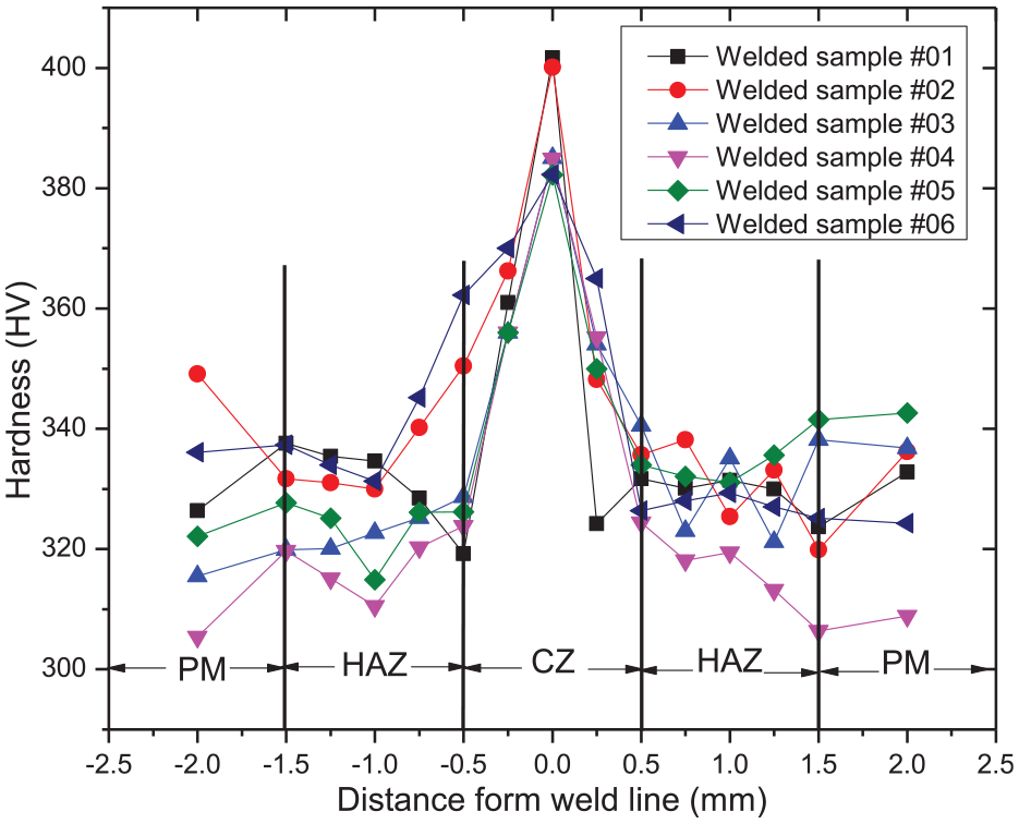
Microhardness at the centre line.
The experimental results in Figure 7 show that the HV hardness at the centre line increases from approximately 380 HV to 400 HV. The hardness measured in the six welded samples, namely, # 01 to # 06, is 401.7 HV, 400.1 HV, 385 HV, 384.9 HV, 382.2 HV and 382.3 HV, respectively. The experimental results reveal that the material hardness in the welded areas is much higher than that of the parent material. This increase in the microhardness is due to compression during the forging process. In particular, the hardness of welded samples #01 and #02 is slightly increased compared to that of the remaining welded samples. This can be explained by the fact that the low rotational speed causes the coefficient of friction to increase so that the input heat of the welding process increases dramatically. Moreover, the high friction pressure during the welding process of these two welded samples also increases the temperature in the welded area. Therefore, the cooling rate of these two welded samples occurs faster than that of the other samples due to the higher temperature at the weld surface, which causes fine grains in these two welded samples compared to the grains in the rest of the weld. 19
Thus, a low rotation speed and high pressure create welded joints with a high microhardness. However, the hardness of welded sample #6, which is made with a higher forging pressure than that of welded samples #1 and #2, is smaller than the hardness of these two specimens. This can be explained as follows: since welded sample #6 is processed with a number of revolutions of 1500 rpm, which is larger than the number of revolutions of 1200 rpm of samples #1 and #2, the coefficient of friction in that case may be lower. Therefore, the heat generated is lower, resulting in a reduced hardness. This result also coincides with the conclusions of the researchers in Da Silva 21 and Li et al. 22 In addition, the HV hardness measured for welded samples # 01 and # 02 are almost the same, indicating that small changes in the time of forging do not affect the HV hardness. Both welded samples # 01 and # 02 are fabricated with a high forging force, so the hardness of the material in the welded area of these two welded joints is higher than that of the other samples. However, the forging force is high, so it reduces the length of the welded parts. Therefore, the technical parameters need to be balanced between two factors: the HV hardness and the remaining length of the part after welding.
The experimental results presented in Figure 7 also show that there is a small difference in the microhardness between the HAZ and parent material. The hardness measured in this zone is also erratic. In the same welding pattern, the HV hardness decreases at locations located far away from the centre line in the radial direction, as shown in Figure 8. For example, the results of the hardness measured for welded sample # 01 show that at point 0, the hardness is 401.7 HV; at the 1.5 mm point, it is 378.8 HV; at the 3 mm point, it is 362.8 HV; at the 4.5 mm point, it is 341.9 HV; and at the 6 mm point, it is 344.9 HV. The microhardness of the remaining welded samples #02 and #03 also have similar distributions. It could be concluded that there is a decrease in the HV hardness in the radial direction of welded joints.
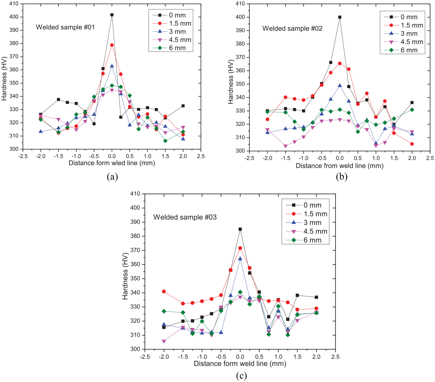
Microhardness measured in the radial direction: (a) measured hardness of welded sample #01, (b) measured hardness of welded sample #02, and (c) measured hardness of welded sample #03.
Influence of the technical parameters on the tensile strength
The equipment used for the compression tensile experiments is shown in Figure 9. This equipment can be used to measure tensile, peeling, deformation, tearing, adhesive and puncture forces.
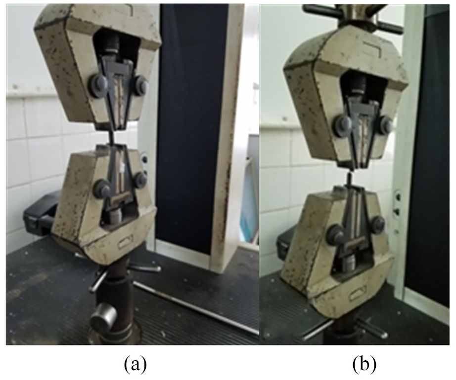
Compression tensile testing experiments: (a) during the tensile test and (b) upon completion of the tensile test.
The welded samples used in the experiments for tensile strength include #01, #02, #03 and #05. Each welded sample is cut into two slices, including the central position and edge position, as shown in Figure 10. The experimental results are listed in Table 2.
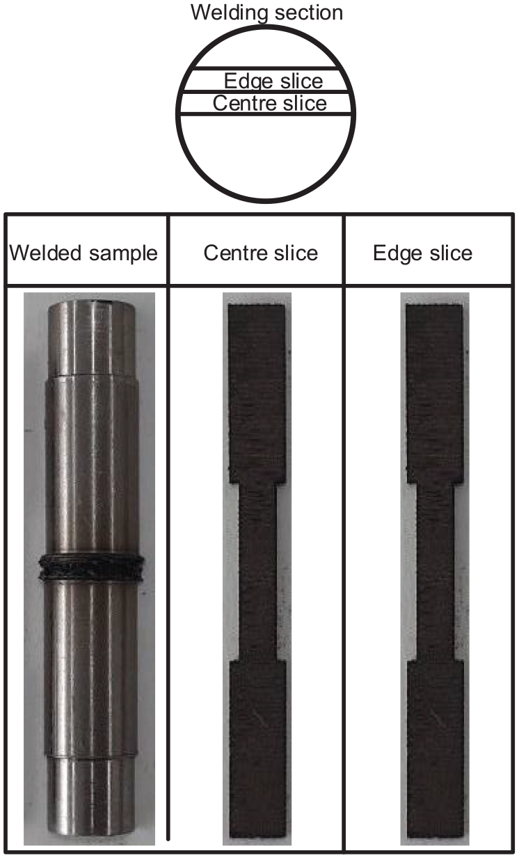
Samples for the tensile strength test.
Tensile strength experimental results.
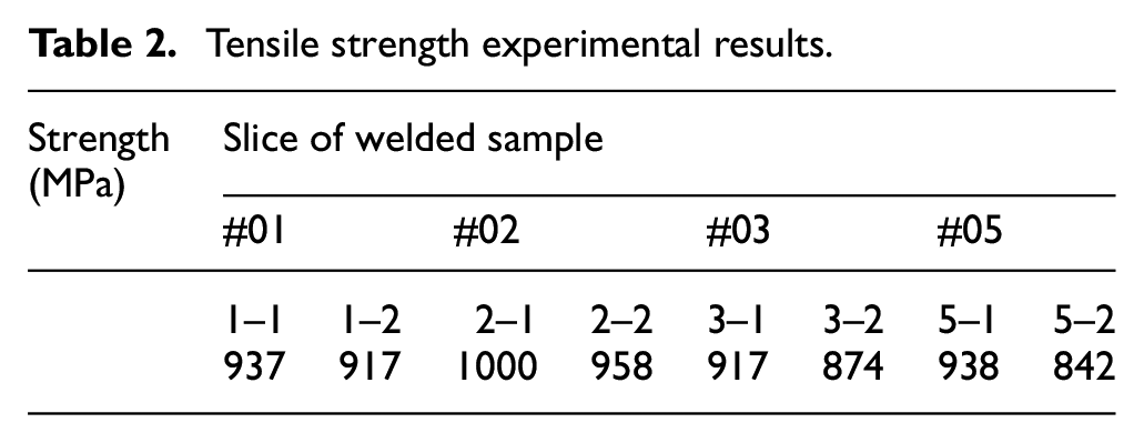
To reduce the length of the manuscript, the paper only presents the stress-strain curve of welded sample #01 at the central (1–1) and edge (1–2) positions, as shown in Figure 11. The fracture stress of the edge slice is lower than that of the centre slice, as shown in Figure 11. The stress-strain curves of the other welded samples also have similar shapes.
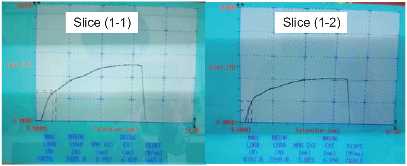
The stress-strain curve of the weld positions in sample #01.
The experimental results in Figure 12 show that all the welded samples are broken at locations that are outside of the welded area; specifically, the fracture position has a distance of 5–10 mm from the welding line. This is also consistent with the experimental results obtained for the HV hardness shown in Figure 7.
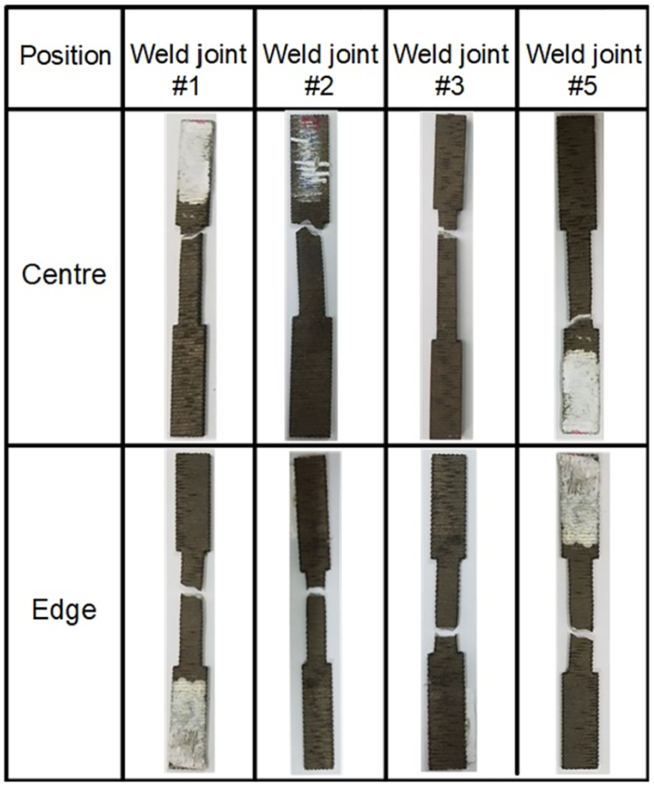
Location where the central slices and the edge slices broke during the tensile strength test.
Figure 13 shows the effect of the welding friction parameters on the tensile strength of the welded joints. The experimental results in Figure 13(a) show that if the axial pressure is increased, then the tensile strength of the welded joints also increases. However, if the time of friction is reduced, then the tensile strength tends to increase, as shown in Figure 13(b). If the number of revolutions increases, then the tensile strength also increases at the centre line, but it decreases substantially at the edge of the weld, as shown in Figure 13(c). It can be concluded that the welding quality is not uniform with respect to the radial direction. It can be deduced from equations (1) that the temperature increases gradually at positions along the radial direction during the friction period because the velocity is proportional to the radius. In addition, the forging pressure at the interface is also different in the radial direction due to changes in the tension. For the Ti6Al4V alloy, the stress is strongly related to temperature and decreases with increasing temperature.4,8 Therefore, the stress in the centre line of the welded joint is the highest. The tensile strength in the edge weld joint is smaller than the tensile strength in the centre weld joint. The radial difference becomes substantial with an increase in the radius of the part. This means that the parts that undergo rotating friction welding must have a limited diameter.
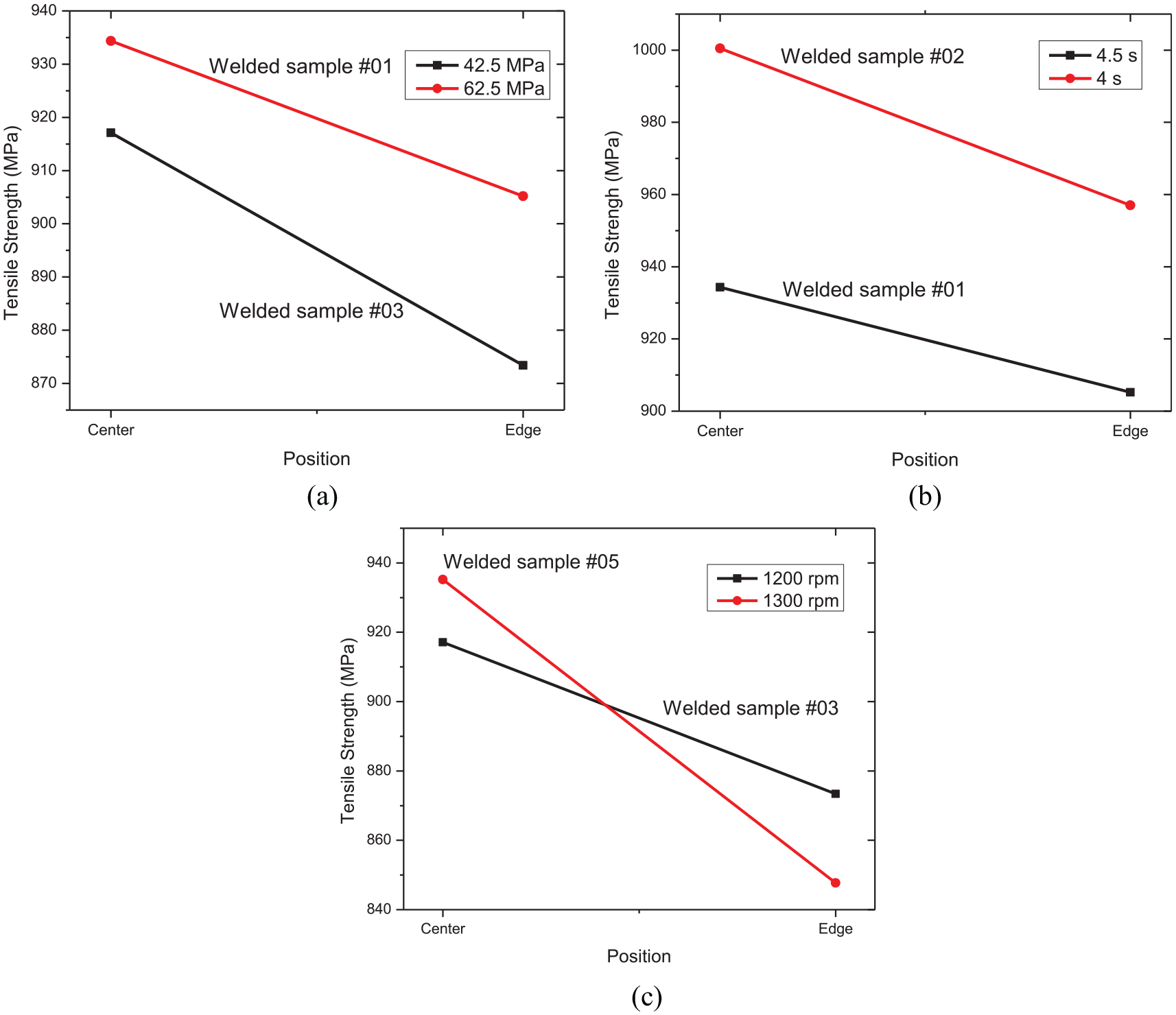
The effect of the welding friction parameters on the tensile strength: (a) influent of the forging pressure on the tensile strength, (b) influent of the friction time on the tensile strength, and (c) influent of forging pressure on tensile strength.
Generally, the heat supplied during the welding process is a technological factor that determines the success of friction welding for Ti4Al6V. 13 However, the most important parameter that affects the weld quality is the axial pressure. This factor strongly affects the tensile strength and microhardness of the welded joint.
Conclusion
This study presents the influence of rotary friction welding parameters on the HV hardness and tensile strength of Ti6Al4V alloy friction welded joints. The axial pressure is the factor that determines the quality of the weld. For rotational friction welding, the tensile strength and hardness decrease in the radial direction. Therefore, the radius of the parts during rotating friction welding must be limited because the quality of the welds at the edge of the part becomes poor. If the axial pressure is high, then the HV hardness and tensile strength increase. An increased forging pressure can be used during rotary friction welding to reduce the radial differences in the mechanical properties of the welded joints. However, this may reduce the length of the welded parts. The following conclusions are derived from this study:
Microstructures vary in welding areas due to the difference in the change in temperature.
The parameter that impacts the tensile strength the most is axial pressure. A high forging pressure in the weld zone, which produces fine, equiaxed, and recrystallized grain structures in the welded joint, results in a high tensile strength and microhardness.
If the rotation speed is changed slightly, then its effect on the weld quality is negligible if the diameter of the welding element is less than 15 mm.
An optimal set of friction welding parameters for Ti4Al6V can be proposed as follows: a rotation speed of 1200 rpm, friction time of 4 s, friction pressure 40 MPa, and forging pressure of 62.5 MPa.
Footnotes
Declaration of conflicting interests
The author(s) declared no potential conflicts of interest with respect to the research, authorship, and/or publication of this article.
Funding
The author(s) disclosed receipt of the following financial support for the research, authorship, and/or publication of this article: This research is funded by Ho Chi Minh City University of Technology, VNU-HCM, under grant number BK-SDH-2020-8140019.
Data availability statement
The data used to support the findings of this study are included within the article.