
Abstract
Micro-milling technology is an efficient method for machining titanium alloy thin-walled micro parts. However, the machinability of thin-walled microstructures can be greatly affected by chatters due to their weak stiffness, especially in difficult-to-machine materials like titanium alloys. In order to obtain high-quality thin-walled micro parts, a chatter mitigation strategy is presented and its mechanism is analyzed in this paper. The titanium alloy workpiece is submerged into a kind of high-viscosity fluid, which can improve machining stability by increasing the damping of the micro-milling process. The stability lobe diagrams (SLD) are established, and the machinability is analyzed and compared under different machining conditions. The cutting force, surface roughness, micro-tool wear, and dimension accuracy of thin-walled micro parts are selected as the evaluation criteria for the machinability assessment. Well-designed micro-milling experiments are carried out under dry, lubrication, and chatter mitigation conditions using the same cutting process parameters. The results show that the use of cutting fluid can effectively improve machinability under stable cutting processes, but the effect of cutting fluid is weakened under chatter machining. The proposed chatter mitigation strategy can suppress regenerative chatter throughout the micro-milling process for thin-walled micro parts and improve their machinability comprehensively.
Keywords
Introduction
Thin-walled microparts are widely used in many emerging fields, including the fabrication of key components in THz slow-wave structures, micro heat sinks, microturbines, microfluidic chips, etc.1–3 Therefore, their machining quality has an important influence on product service performance. 4 The machining quality can be evaluated by machinability, which refers to surface integrity, tool life, burr formation, cutting forces, dimension accuracy, productivity, etc.5,6 Among all the fabrication methods, micro-milling has the advantages of high machining accuracy, high machining efficiency, and low machining energy consumption, which make it effective for thin-walled micro parts machining. 7 However, micro-milling the thin-walled parts is still a challenging task. Because the heavy specific cutting forces can cause deflections of the micro-tools and the tiny structures due to their low stiffness, which leads to variations in the instantaneous cutting thickness and cutting forces. 8 Over the past years, many relevant studies have been conducted in order to improve micro-milling machinability. However, most of the previous research focuses on the perspective of cutting parameters.9–12 The mechanism destroying micro-milling machinability has not been revealed fully.13,14
In the micro-milling of thin-walled parts, regenerative chatter is one of the main challenges due to the low stiffness and high spindle speed of the machining system, which makes it the most direct and unfavorable factor causing the decrease in machinability. 15 Micro-milling instability can lead to poor surface integrity, premature tool failure, low machining efficiency, etc. 16 Therefore, the chatter avoidance method is of great importance, for which the SLD is often employed to find the stable cutting region.17,18 SLD consists of the critical depth of cut for chatter-free machining under each spindle speed, and machinability can be improved using the cutting parameters in its stable region. 16 However, the maximum depth of cut in stable micro-milling operations is usually small, especially for difficult-to-machine materials like Titanium alloy, etc. Choosing cutting parameters conservatively can avoid chatters, but machining quality is not the only priority, machining efficiency is also important in the micro-milling process. 19 In this sense, a method that can expand the stable machining region in SLD is necessary for the comprehensive improvement of the machining quality and machining efficiency. 20
Many scholars have made unremitting efforts in micro-milling chatter mitigation. Some pointed out that decreasing cutting force will benefit stability, so coated tools and cutting fluids are employed in micro-milling to reduce the friction between cutting tools and workpieces. 21 The results show that these methods can certainly enlarge the stable cutting area to a certain extent compared with dry machining with uncoated cutters, but the effect is not so obvious. 22 Besides, other chatter mitigation strategies have been proposed. Non-standard micro-tools can interrupt the generation of regenerative vibration. After the optimization of teeth number, shank diameter, and other important geometries of the micro-tool, the allowable cutting depth for chatter-free machining has been improved. 23 In addition, the dynamic characteristics have great impacts on the micro-milling stability. The vibration energy can be dissipated by the damping, so the tuned mass damper has been employed in chatter mitigation, which exhibits excellent performance by expanding the stable region by 13 times. 24 The design parameters were optimized by the genetic algorithm, and the nonlinear damper has better performance in chatter mitigation compared with linear damping. 25 Ultrasonic vibration assistance has been proven effective in micro-milling chatter mitigation, which leads to the periodic separation between the micro-tools and the workpieces, expands the effective rake angle of the tool, and makes it easier for the cutting fluid to enter the cutting area. 26 In addition to expanding the stable machining area of the SLD, some active chatter mitigation methods have been proposed, in which the piezo actuator is employed to compensate for regenerative vibrations. 27 However, the hysteresis effect is still needed to be further investigated and the equipment is too expensive and complex. 28
To sum up, the main obstacle restricting micro-milling machinability is regenerative chatter, especially in the fabrication of thin-walled micro parts due to the low stiffness.29–31 Therefore, an effective chatter mitigation method is needed.27,32 Many meaningful methods have been put into practice, but they also have limitations. Additional equipment is basically required which is expensive to implement and complicated to install. 33 Therefore, their large-scale applications have been restricted, and an easy, inexpensive, and effective chatter mitigation method is in urgent need.
The vulnerable stiffness characteristics of thin-walled micro parts make them different from the general micro-milling processes. However, the influence of micro chatters on machinability during the machining process has not been discussed systematically. In this paper, a novel chatter mitigation strategy for micro-milling thin-walled micro parts is presented using high-viscosity fluid. Its feasibility is verified by well-designed experiments under dry machining and chatter mitigation machining conditions. The dynamic parameters are obtained and the SLDs are established, respectively. The machining parameters are selected according to the SLD and the chatter mitigation effect has been validated from the perspectives of surface roughness, tool wear, cutting forces, and dimension accuracy. In addition, the effects of cutting fluids and cutting parameters in improving machinability are also discussed and analyzed.
Experimental setup and mechanism of chatter mitigation
Micro-milling experiments for titanium alloy thin-walled micro parts under various machining conditions are carried out on a KERN Evo five-axis machining center, as shown in Figure 1(a). The spindle speed of the Kern machining center can reach 50,000 r/min, and the positioning accuracy in the three directions of x, y, and z can reach ±0.5 μm, which guarantees a high machining accuracy. Therefore, the influence of machine tool errors on the machining quality can be ignored. The lubricating system on the machining center is shown in Figure 1(b). The cutting fluid used in the experiment is Blasocut’s environmentally friendly cutting fluid, which has good cooling and lubricating effect. Figure 1(c) shows the experiment setup for micro-milling chatter mitigation. A container is installed on the workbench and filled with high-viscosity liquid. In order to prevent the negative effects of chatter during micro-milling on the machinability of thin-walled parts, the titanium alloy workpiece is immerged into the high-viscosity fluid, which is silicone oil with a viscosity of 800 mm2/s in this experiment.
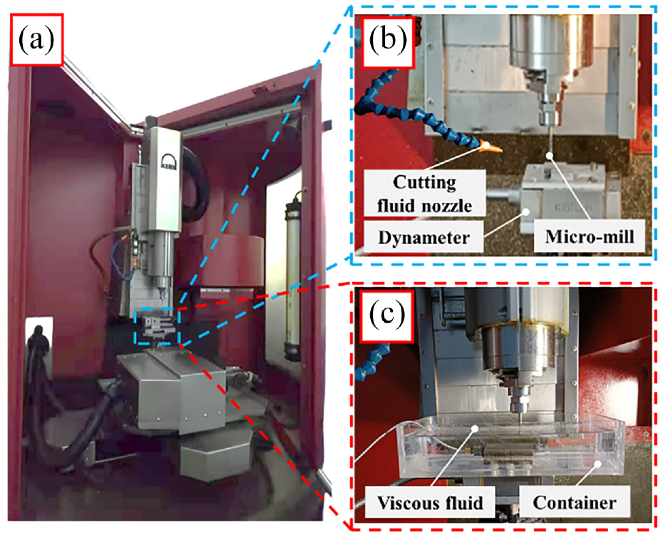
Experimental setup: (a) kern machining center, (b) dry and lubrication machining setup, and (c) chatter mitigation machining setup.
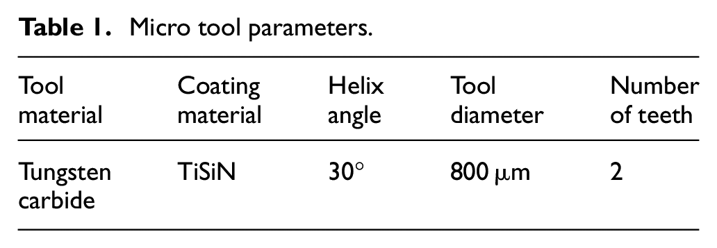
All the micro-mills used in the experiments are purchased from the same batch. Their main parameters are listed in Table 1.
Micro tool parameters.
The type of titanium alloy workpiece employed in the experiments is Ti-6Al-4V. Its main mechanical properties are listed in Table 2.
Mechanical properties of Ti-6Al-4V.
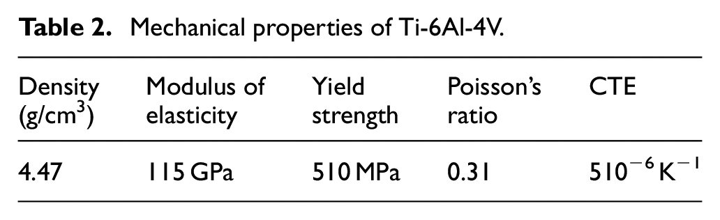
Figure 2 is the schematic for the thin-walled workpiece dimensions. The width and height of the thin walls are 200 and 1000 μm, respectively. The cutting length of each micro mill is 1000 mm.
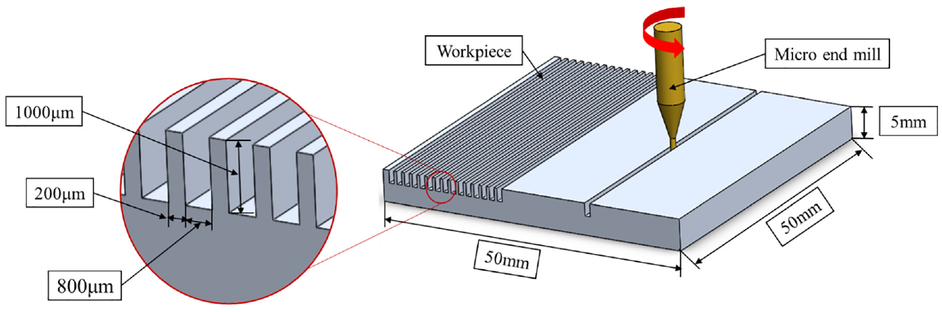
Schematic of micro-milling of thin walls.
The surface roughness, tool wear, dimension error, and cutting force are measured as criteria for evaluating the machinability of titanium alloy thin-walled micro parts. The white light interferometer in Figure 3(a) is used to measure the surface topography, the coaxial imager in Figure 3(b) is used to measure the thickness of thin-walled parts and tool wear, and the Kistler dynamometer in Figure 3(d) is used to measure the cutting Force. Besides, the dynamic analyzer in Figure 3(c) is used to measure the dynamic parameters of the workpiece to illustrate the damping effect of viscous fluid.
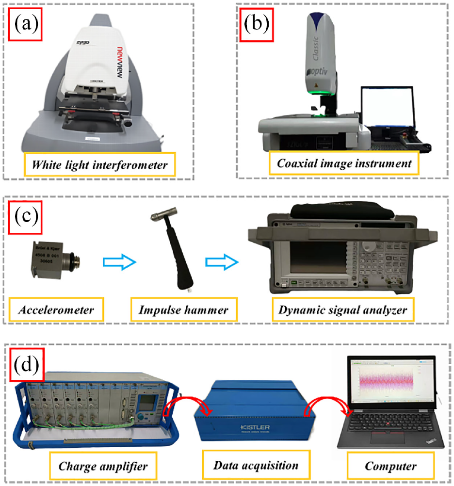
Measuring equipment for machinability analysis: (a) surface topography, (b) tool wear and dimension error, (c) dynamic characteristics, and (d) cutting force.
To further illustrate the effectiveness of the proposed chatter mitigation method during micro-milling. The frequency response functions and first-order dynamic parameters under dry machining and chatter mitigation machining are obtained in Figure 4 and Table 3, respectively.
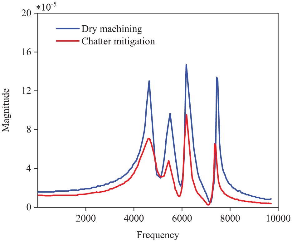
The frequency response function of dry machining and chatter mitigation machining.
First-order dynamic parameters of the micro-milling system.
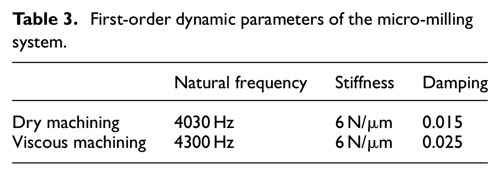
It can be observed from Table 3 that the micro-milling damping coefficient is enlarged by the viscous liquid, which leads to the expansion in the stable cutting region, while the natural frequency and stiffness are almost unchanged.
Besides, the SLD is established and verified according to the method proposed in Song et al. 34 at the feed rate is 100 mm/min, as shown in Figure 5. The critical depth of cut for chatter-free machining increases at each spindle speed when the damping is enlarged. In addition, from the perspective of cutting parameters, increasing the spindle speed is beneficial to machining stability according to the SLD.
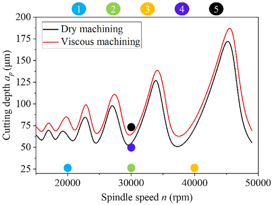
The SLDs of dry machining and chatter mitigation machining.
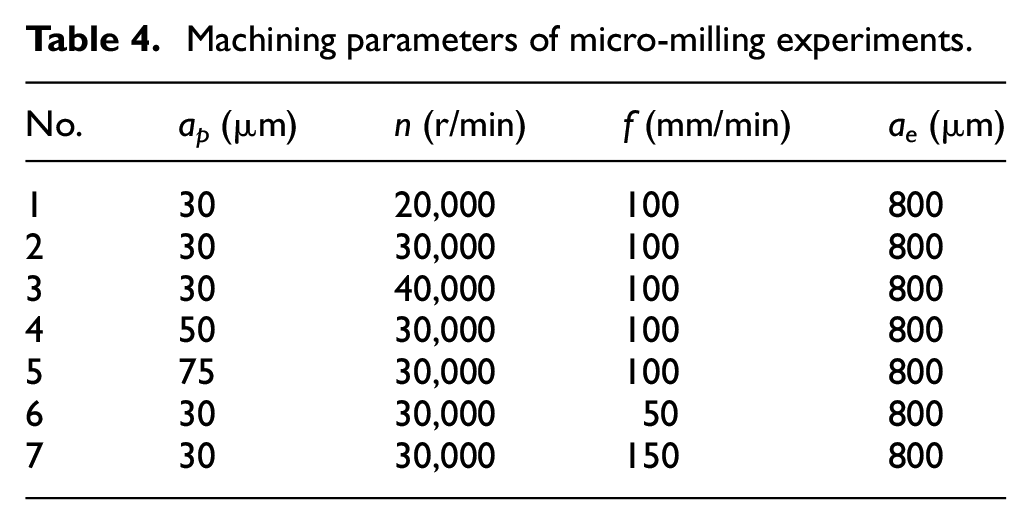
On this basis, the first five groups of cutting parameters are selected, which are listed in Table 4. In order to illustrate the effect of feed rate on machinability, the sixth and seventh groups of cutting parameters are selected. The same cutting parameters are employed in the dry, lubrication, and chatter mitigation machining conditions. Each set of experiments is repeated three times, and the experimental results are within the 95% confidence interval.
Machining parameters of micro-milling experiments.
Results and discussion
After conducting three groups of micro-milling experiments under three different machining conditions. The cutting force, surface roughness, dimension errors, and tool wear under different cutting conditions are measured and analyzed in this section.
Cutting force
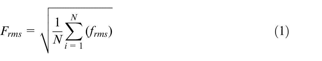
Cutting force is one of the most important indexes reflecting the performance of the micromachining process, which has an essential influence on surface quality, dimension accuracy, and tool wear. At the same time, the chatters in the micro-milling process can also be detected by analyzing the cutting force signals. Figure 6 shows the variations of the average cutting forces with cutting parameters under dry and lubrication cutting conditions. The cutting forces are calculated according to equation (1). Where Frms is the root mean square of the sampling cutting force frms, and N is the number of sampling points.
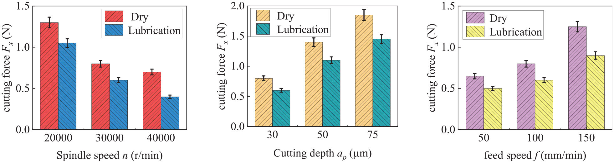
Cutting force variations with cutting parameters.
It can be observed in Figure 6 that using cutting fluid can reduce the average cutting force under each group of cutting parameters. This is caused by the lubrication effects in the cutting area, which can reduce friction between micro-tools and the workpieces. At the same time, the cutting force has a decreasing trend as the spindle speed increases. Because higher cutting temperatures will soften the workpiece material. In addition, the average cutting forces show an increasing trend as the feed rate increases, which is caused by larger cutting thickness. Besides, larger depths of cut will certainly lead to growth in average cutting forces.
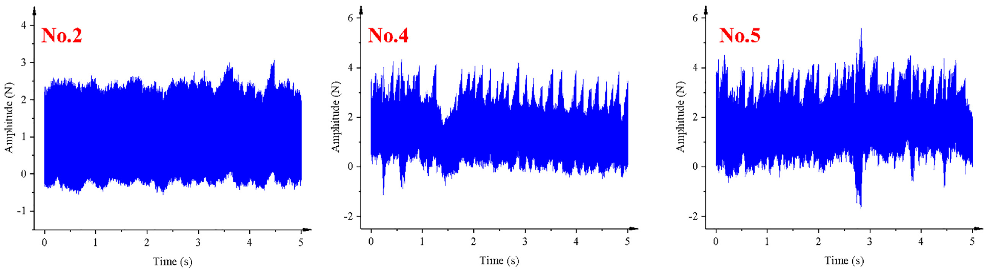
In relation to the above analysis, it seems that there is no difference between the fabrication of thin-walled parts and the general micro-milling process. However, compared with the common micro-milling processes, the machining of thin-walled micro parts presents its own features. Due to the small size and low stiffness, chatter is inevitable when the depth of cut exceeds a threshold, which will cause negative impacts on machinability. In order to detect the chatters in the micro-milling process, the time-domain cutting forces in dry machining are measured and shown in Figure 7(a) for the second, fourth, and fifth experiments. The cutting force signals are not filtered, and the sampling frequency is 10,000 Hz. The signals recorded before machining are used to compensate for the measured values during machining. In addition, the corresponding power-frequency analysis is carried out, as shown in Figure 7(b), in which the magnitudes of cutting force have severe fluctuations in the fourth and fifth experiments. As a comparison, the high-frequency components can be found in the corresponding power spectrum as shown in Figure 7(b). While the power of the second experiment mainly concentrates on 500 and 1000 Hz, which are spindle and tooth-passing frequencies, respectively. This phenomenon is consistent with Figure 5, for example chatters will occur when the depth of cut exceeds the critical value.
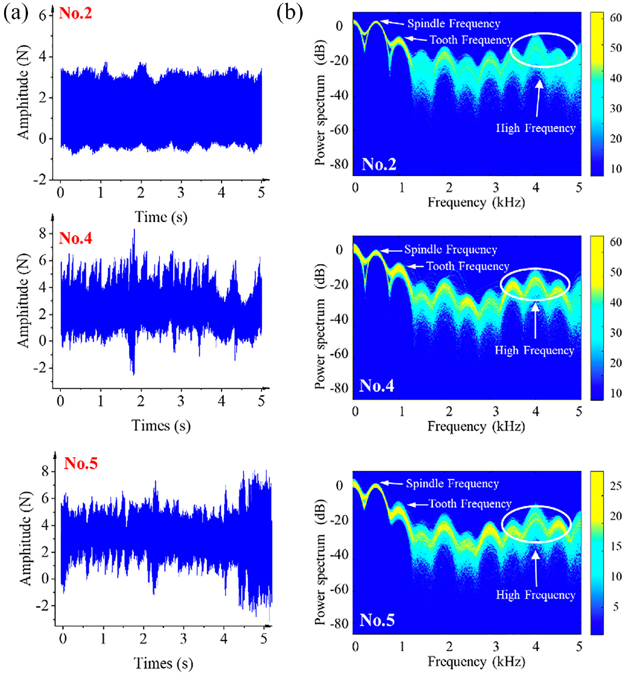
Cutting force analysis under dry machining: (a) time domain cutting force variations and (b) power-frequency analysis of cutting forces.
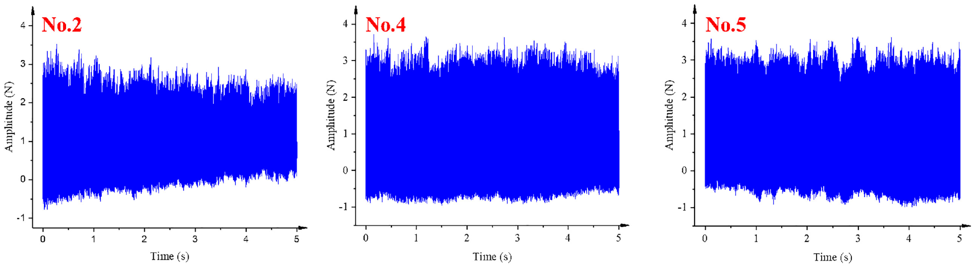
Figure 8 shows the time-domain cutting forces under lubrication machining conditions. The results indicate that the application of cutting fluid can reduce the amplitude of cutting forces, but it cannot suppress regenerative chatters effectively.
Time-domain micro-machining forces under wet machining.
In order to validate the proposed chatter mitigation strategy, the cutting forces of the corresponding conditions are analyzed in Figure 9. The results show that the cutting forces are steady and chatters can be suppressed effectively by increasing micro-milling damping.
Time-domain micro-machining forces under chatter mitigation machining.
Surface roughness
The bottom surface is used to characterize the surface topography, as shown in Figure 10. In addition, the morphologies of the bottom surface are measured by the white light interferometer and compared under different machining conditions, as shown in Figure 11.
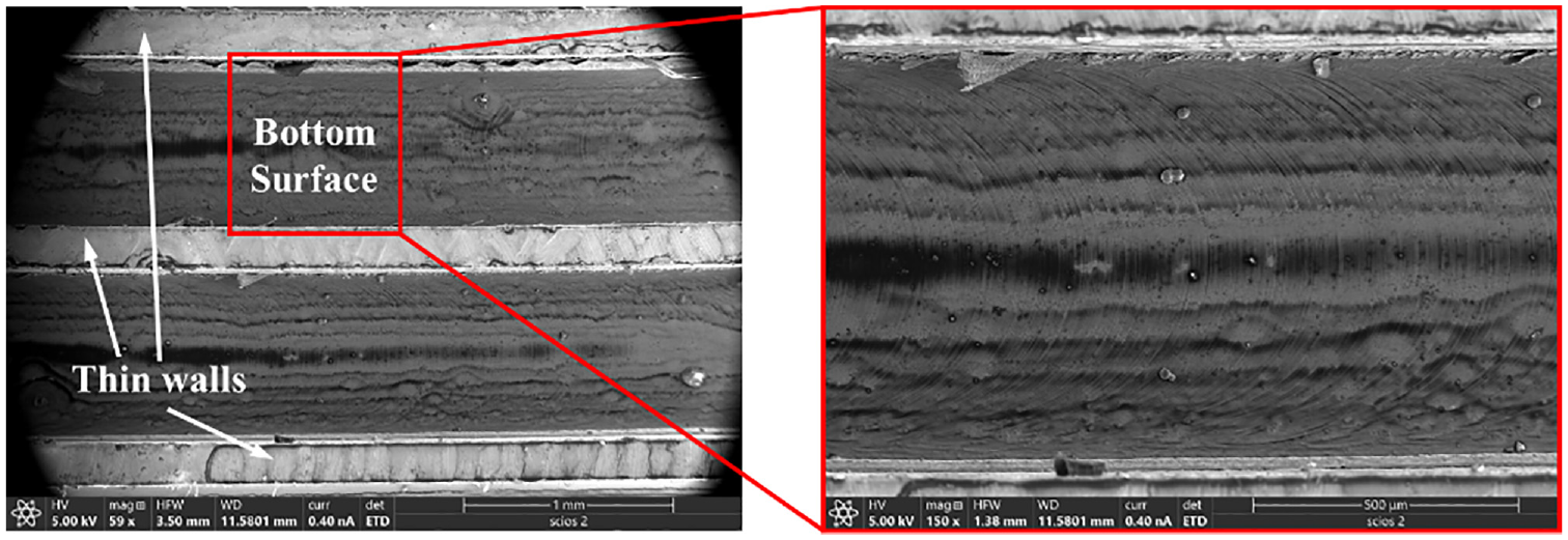
The bottom surface that measured by SEM.
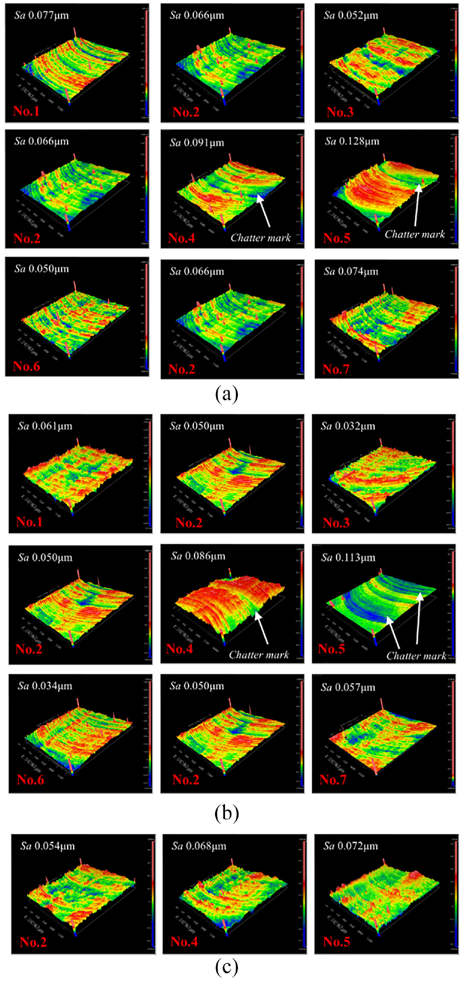
The surface morphologies under different machining conditions: (a) dry machining conditions, (b) lubrication machining conditions, and (c) chatter mitigation machining conditions.
In the fourth and fifth experiments, obvious chatter marks can be observed in the dry and lubrication machining. However, there is no chatter mark in the chatter mitigation machining process in the corresponding experiments, which indicates the mitigation of regenerative vibration is beneficial for surface integrity.
Surface roughness is a commonly used indicator of machinability for its significant impact on product performance. Reasonable selections of cutting parameters can improve surface quality. Therefore, the influence of cutting parameters on surface quality is discussed first, and their variation trends under different conditions are shown in Figure 12. Under different conditions, the increase of the spindle speed can lead to smaller surface roughness. While the increase in the cutting depth and the feed rate will cause opposite results. This result is consistent with the SLD, in which the increasing spindle speed will enlarge stable cutting depth. Besides, the best combination of cutting parameters can be obtained. In dry machining, the minimum surface roughness Sa is 0.05 μm, which can be obtained at the spindle speed is 40,000 r/min, the feed speed is 100 mm/min, and the depth of cut is 30 μm. In lubrication machining, the minimum surface roughness Sa is 0.032 μm, which can be obtained at the spindle speed is 30,000 r/min, feed speed is 50 mm/min, and depth of cut is 30 μm. The result indicates the surface quality can be improved using cutting fluid
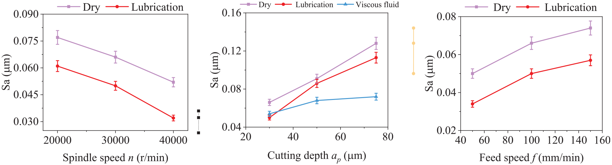
Surface roughness variations with cutting parameters.
In order to have an in-depth understanding on surface quality improvement, the effects of different methods are compared in Figure 13. For the use of the cutting fluid, the largest promotion can be observed in the third experiment, but the promotion effects in the fourth and fifth experiments are not obvious. This result indicates that the surface quality can be greatly improved by cutting fluid in the stable cutting process. As for the unstable cutting process, the main reason for deteriorating surface quality is regenerative vibration, in which the effect of cutting fluid is not as obvious as the viscous liquid.
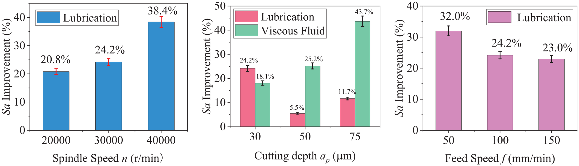
Sa improvements under lubrication and chatter mitigation conditions.
Dimension errors
Chatter vibration has more pronounced effects on dimensions perpendicular to the machining direction. Therefore, dimensions in the width direction have been measured and analyzed. In addition, the vertical dimensions have been measured as supplementary, as shown in Figure 14.
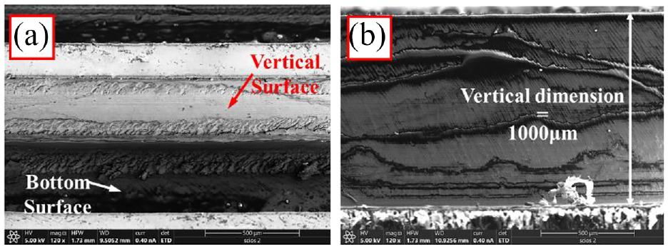
(a) Schematic diagram of thin-walled structure and (b) vertical dimension of the thin-wall.
Both the thin-walled structures and the micro-tools will deform under the action of periodic milling force due to their low stiffness, which makes dimension errors unavoidable after the micro-milling process. Therefore, the dimension accuracy of thin-walled parts is selected as an index to reflex the machinability in this study. The corresponding schematic diagram is shown in Figure 15.
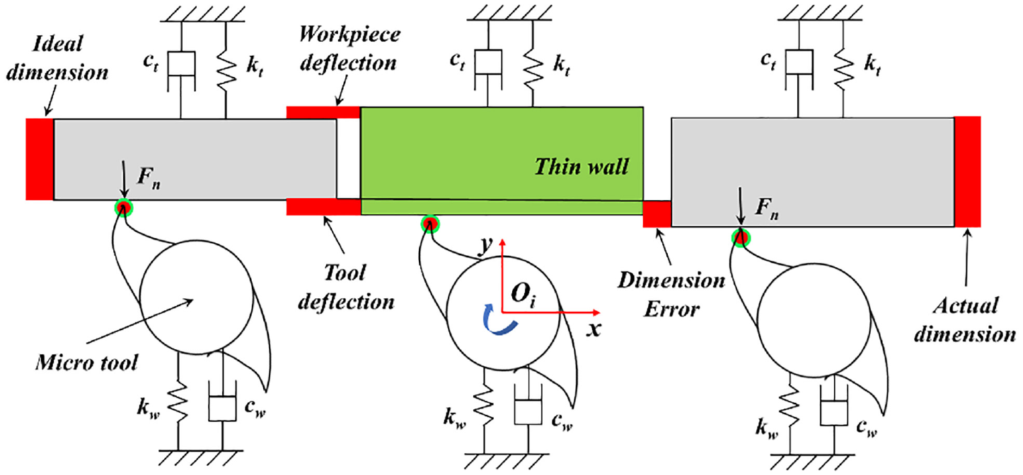
Schematic of dynamic deflections of the micromachining system.
The dimensions of thin-walled parts under different machining conditions are shown in Figure 16 and variation laws of the dimension error are shown in Figure 17.
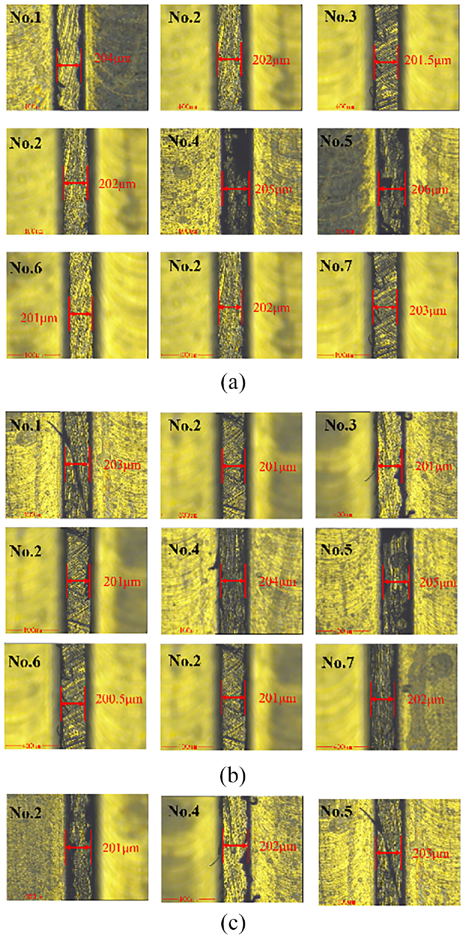
Dimensions of thin-walled parts after machining: (a) dry machining conditions, (b) lubrication machining conditions, and (c) chatter mitigation machining conditions.
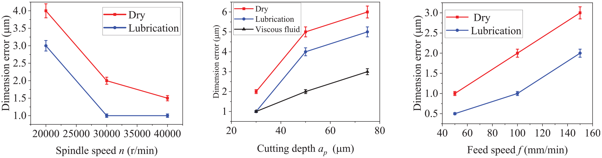
Dimension error variations with cutting parameters.
The dimension errors of thin-walled parts have similar variation trends as the average cutting force, which indicates that cutting force is the main factor reducing the dimension accuracy. However, the micro-milling process is not static, for example the dimension accuracy is not just determined by the stiffness of the workpiece and the dynamic characteristics need to be taken into consideration. In Figure 17, the dimension accuracy of the fourth and fifth experiments has been improved effectively in chatter mitigation conditions. Because the fluctuations of micro-milling force caused by chatters also play an important role in reducing dimension accuracy but it can be improved by the proposed chatter mitigation method.
Tool wear
Titanium alloy is one of the most difficult-to-machine materials for its low thermal conductivity and small elastic modulus. Micro tools experience greater specific stress during micro-machining, so tool wear is inevitable, especially the uncoated ones. In return, the worn tools will cause damage to surface quality and dimension accuracy. Therefore, extending tool life is of great significance, but the wear evaluation criterion of micro-tools has not been unified at present.
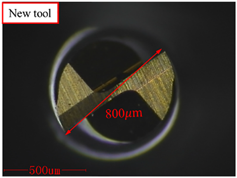
In the micro-milling process, the cutting-edge radius has an important influence on the material removal mechanism due to the scale effect. Therefore, reduction in tool diameter is chosen as the most important metric for microtool wear, because it is easy for measuring and can reflect the loss of cutting-edge radius. The bottom view of a new tool is shown in Figure 18.
Bottom topography of a new micro-tool.
The variation laws of tool diameter reduction with cutting parameters are shown in Figure 19. The reduction of the microtool diameter is smaller in lubrication machining compared with dry machining. Because the friction between the tool and the material can be reduced and heat generated during the machining process can be taken away by the cutting fluid. The results show a similar trend to the average cutting force, which indicates the loss in tool diameter is dependent on the friction between cutting tools and the workpieces. Besides, it can be observed in Figure 20, viscous liquid can reduce tool diameter wear as well, but the effect is not as good as the cutting fluid.
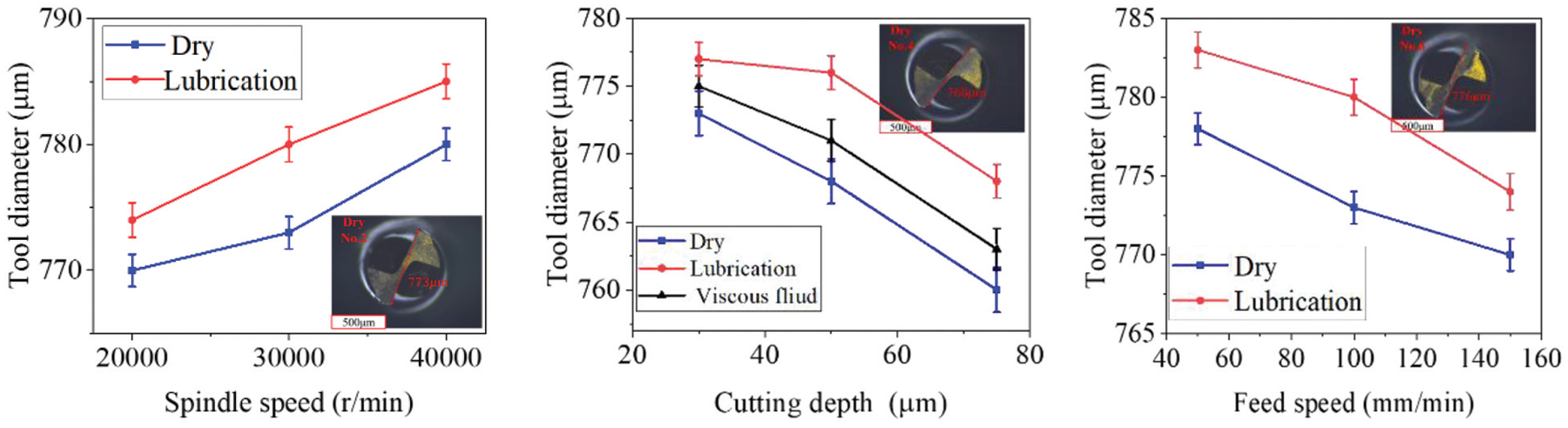
Tool diameter deviations with cutting parameters.
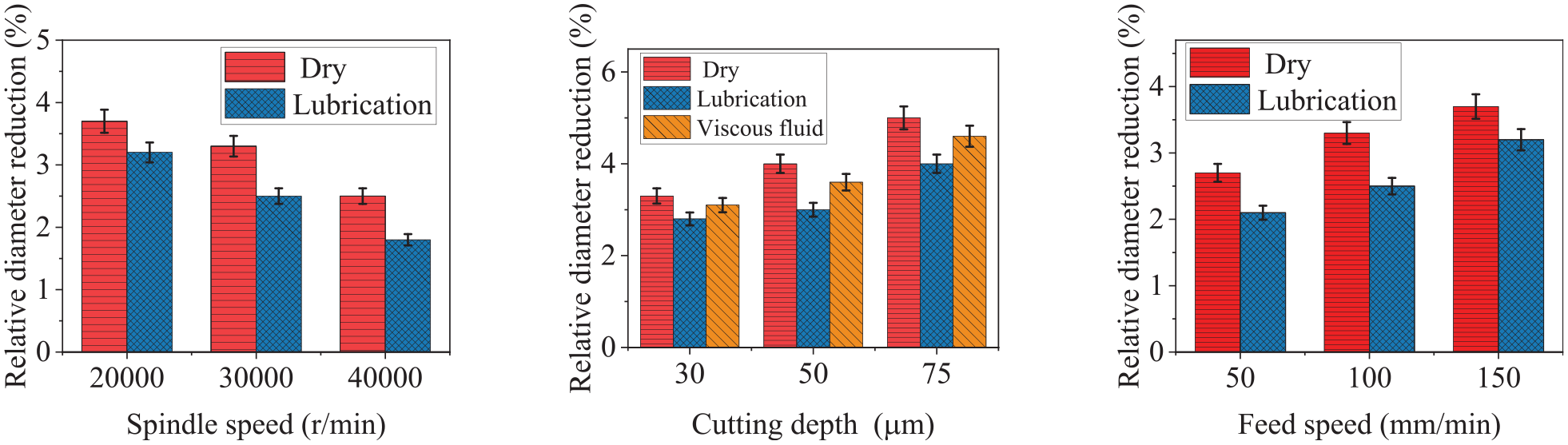
Relative diameter reduction variation with cutting parameters.
In order to characterize the tool wear more comprehensively, the morphology of the cutting edge is compared under different machining conditions. The cutting edge of a new tool is shown in Figure 21(a). The cutting-edge experience chipping damage when chatter occurs under dry cutting conditions as shown in Figure 21(b). The chipping will be reduced to a certain extent in lubrication machining conditions as shown in Figure 21(c). However, the chipping can be effectively suppressed in viscous liquids as shown in Figure 21(d), which indicates that chatter is the main reason causing cutting-edge chipping.
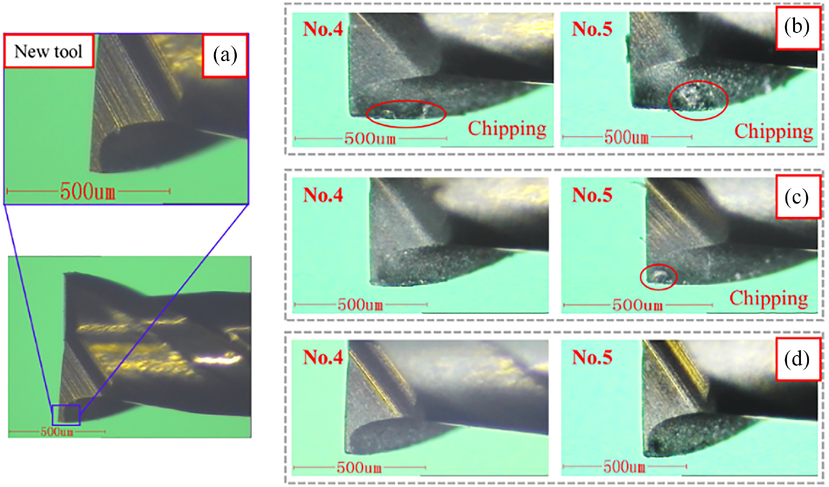
The cutting edge of micro-tool: (a) new microtool, (b) dry machining condition, (c) wet machining condition, and (d) chatter mitigation condition.
The adhesive wear can cause the falling-off of tool coatings, which can increase the friction between the tool and the workpiece, and reduce the strength of the tool and tool life. Therefore, the morphology of the minor flank surface of the microtool is also measured. The morphology of a new tool minor flank is shown in Figure 22(a). Serious material adhesion can be found on the tool minor flank in the dry machining as shown in Figure 22(b) after the micro-milling process. As for the elimination of material adhesion, the effect of viscous liquid is not as obvious as the cutting fluids as shown in Figure 22(c) and (d).
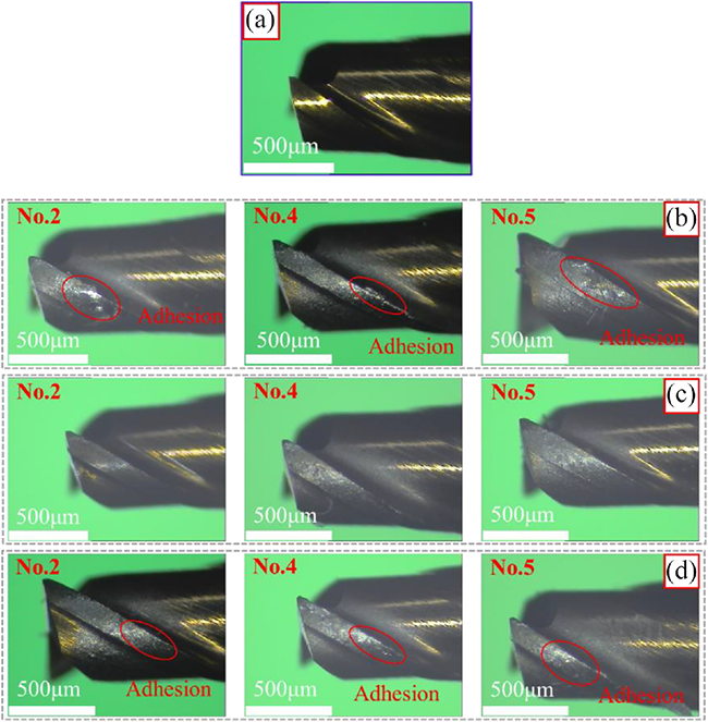
Material adhesion of minor flank face: (a) new microtool, (b) dry machining condition, (c) wet machining condition, and (d) chatter mitigation condition.
Conclusions
The machinability of micro-milling titanium alloy thin-walled parts was investigated under dry, lubrication, and chatter mitigation cutting conditions in this study. The machinability is evaluated by the measurement and analysis of cutting forces, surface roughness, dimension accuracy, and tool wear. The results show that the machining conditions and cutting parameters have significant influences on machinability because the improper selection of cutting parameters will cause instability in micro-milling due to its weak stiffness. The application of cutting fluid is not sufficient for chatter suppression, but the chatter mitigation strategy proposed in this paper can expand the stability cutting depth in the micro-milling process by increasing damping.
Specific conclusions can be drawn as follows.
Increasing the spindle speed, reducing the feed rate, and reducing the depth of cut can improve the surface quality under dry, lubrication, and chatter mitigation machining conditions.
Under the same cutting parameters, the cutting fluid can decrease cutting force and improve the surface quality, dimension accuracy, and tool life of micro-milling titanium alloy thin-walled parts for its lubrication effect. However, the effects will be weakened under unstable cutting processes.
The regenerative vibration is detrimental to the machinability of thin-walled Ti-6Al-4V micro parts fabrication. The chatter mitigation method proposed in this work can suppress chatters and improve machinability by expanding the stable cutting range in SLD.
Footnotes
Declaration of conflicting interests
The author(s) declared no potential conflicts of interest with respect to the research, authorship, and/or publication of this article.
Funding
The author(s) disclosed receipt of the following financial support for the research, authorship, and/or publication of this article: This research work was supported by the National Natural Science Foundation of China (Grant No. 52075129).
Data availability
The datasets used or analyzed during the current study are available from the corresponding author on reasonable request.