
Abstract
Machining of slender (low rigidity) parts is associated with tool/workpiece deflections due to induced cutting forces resulting in machining error (dimensional inaccuracy of the machined surface). The development of smart fixtures is seen as an enabler for reduction of machining error. To reduce lead times, the smart fixtures need to be designed in an efficient way by using more virtual simulations and less physical iterations. This paper presents the development of a novel methodology for machining error prediction in milling of a fixture-workpiece system. The methodology integrates a cutting force model, a finite element based fixture-workpiece system and a multi-step error predictive approach. The methodology was first validated on a flexible thin-wall Ti6Al4V slender part where less than 6% difference was achieved between predicted and measured machining error. The difference between predicted and measured cutting forces was approximately 6%. After the gained confidence, the methodology was applied to the flexible thin-wall Ti6Al4V slender part encompassed by a fixture with three actuators acting as supports. The predicted machining error was reduced from the range of 0.2–0.33 mm (no actuators) to the range of 0.12–0.14 mm (with three actuators). This demonstrated the capability of the developed methodology to aid the design of future smart fixtures with the potential to reduce lead times during their development.
Introduction
The accuracy of the machined surface profile is important for the dimensional accuracy of components which are designed to deliver functional performance. 1 Machining induces cutting forces which could cause a deflection to geometrical features with low stiffness leading to the generation of undesirable machining error. 2 Therefore, the use of computational methods for error prediction and error compensation is sought in precision machining to deliver required dimensional accuracy. Fixtures are used to accurately locate and tightly hold the workpiece in machining, assembly and inspection as well as to reduce deflections through purposely designed supports.3,4 The fixture should be able to establish and secure the position of the workpiece throughout the manufacturing operation. 5 During the machining process development stage, a fixture needs to be designed, fabricated and tested. This might require a number of iterations until an optimum fixture is designed and fabricated for the machining process. Therefore, modelling and simulation methodologies can be employed to support the development of smart fixtures to reduce iterations leading to potential reduction of lead times and costs.6,7
Peripheral milling of flexible components is a common machining operation in the aerospace as well as in other sectors. A typical example of peripheral milling is a jet engine impeller. The peripheral milling of the impeller blades is associated with deflections due to the thin nature of the blades and the induced cutting forces.8,9 To address the deflection challenge in peripheral milling, researchers have developed a wide range of approaches in the last three decades. For instance, Kline et al. 10 studied the deflection of a clamped flexible plate in peripheral milling. Altintas et al. 11 analysed the cutting forces and deflections, both dynamically and statically, in peripheral milling of such a flexible plate at a particular location, by neglecting the time varying structural properties and changes in the immersion boundaries. Tsai and Liao 12 analysed the machining error in the peripheral milling of thin-walled workpieces by assuming that the tool and the workpiece deform to their static equilibrium positions. Ratchev et al. 13 developed an analytical cutting force model based on a perfect plastic layer applied to machining error prediction of low-rigidity components. Bolar and Joshi 14 predicted the cutting forces in milling of a thin-wall by applying a three-dimensional, thermo-structural, finite-element-based mathematical model. Zhang et al. 15 predicted the stability in milling using a dynamic model of thin-walled part. Ma et al. 16 applied the elastic deformation theory of thin shells to predict the spring back effect after clamping of thin-walled parts with curved surfaces. Agarwal and Desai 17 utilised a mechanistic cutting force model to estimate the induced cylindricity error during end milling of thin-walled circular components using finite element based framework and particle swarm optimisation algorithm. Yu et al. 18 reported an experimental method based on multi-layer machining for obtaining optimum cutting parameters based on analysing the machining error. The development of comprehensive predictive and experimental methods that consider the structural deflections of the cutting tool/workpiece and the chatter instability requires further research effort to address the milling error challenge as reported in.19,20
The mitigation of machining error could be achieved by applying error compensation approaches (e.g. modification of the toolpath). Rahman et al. 21 presented a modification of the toolpath using a three-dimensional volumetric error model while Bohez 22 presented a general error compensation approach using closed loop volumetric error relations. Cho et al. 23 proposed an integrated error compensation method using inspection database for profile milling. Yang et al. 24 developed comprehensive error compensation strategy using a general fixture layouts. Gao et al. 25 obtained machining errors from the measured force and measured error relationship. Law and Geddam 26 developed a compensation methodology to integrate both the force and deflection models, based on a cutting force model and a discrete deflection model. Ratchev et al. 27 developed machining dimensional form error prediction of low rigidity components by integrating analytical flexible force model and finite element model for prediction of a part deflection. Yue et al. 28 compensated machining error at surface profiles by modifying the toolpath using an off-line compensation algorithm in corner milling. Si and Wang 29 developed an iterative compensation strategy to reduce the tool/workpiece deformation-induced surface error during the five-axis flank milling of thin-walled workpieces by modifying the tool tip position and tool axis orientation.
Despite the existing research in machining error prediction and compensation of tool/workpiece system, the inclusion of a fixture in error predictive models is still immature in its technology readiness. Therefore, the research in this paper is focused on the development of a novel methodology for machining error prediction in milling considering the entire fixture-workpiece system. The novelty of the methodology for error prediction is the holistic integration of a cutting force model, a finite element based fixture-workpiece system and a multi-step error predictive approach. The advantage of the proposed methodology is that it can be used for the design of smart fixtures leading to potential reduction of lead times. The methodology is first validated on a flexible Ti6Al4V slender part without the use of a fixture to gain confidence in the predictability of the cutting forces and machining error. As a demonstrator, the validated methodology is then applied to the flexible slender part supported by three actuators to reduce machining error.
Methodology
A top-level overview of the machining error prediction scheme for smart fixturing systems is shown in Figure 1. The overview is comprised of three main elements. The first element includes the CAD modelling, finite element (FE) meshing and modelling of a fixturing system. The part geometry is generated as a CAD solid model and fed into a FE model. The part is meshed with three degree of freedom elements to accurately describe the stiffness of the part as well as to be coupled with spring elements representing components of the fixture. To represent the realistic stiffness after material removal, the geometry is modified and re-meshed. At each position of the cutting tool, static elastic analyses are performed to predict the deflection caused by the applied cutting forces, hence the stiffness at that position. The second part consists of integration of a virtual spring-damper model, analytical cutting force model and multi-step error predictive approach. These models are nonlinearly correlated in order to achieve an equilibrium state in milling of flexible parts clamped in a deformable fixturing system. To avoid the complexity of the contact modelling in the FE model, the components are modelled with springs and dampers coupled in a virtual spring-damper systems to represent the interaction between the fixture and the workpiece. The non-linear force-deformation profiles of the spring-damper systems are used to emulate the behaviour of fixture components. The machining cutting forces are calculated by considering the changes of the immersion angles on the engaged tooth, which affects the uncut chip thickness. The uncut chip thickness is also affected by the deformation of the flexible part. To find the equilibrium between the induced cutting force and deflection, a multi-step machining error prediction model is developed. In the finite element model, a moving load generated by the cutting force model acting on the engaged cutter edge in the cutting zone following the toolpath is applied to the workpiece. The third part of the scheme is the error analysis and compensation, which can be applied to further mitigate machining error. In smart fixturing systems, actuators can be used as supports to control the machining induced deflections and potential vibrations. 2 The milling error prediction scheme can be used to optimise the position and the number of actuators to minimise the machining error. Furthermore, the actuators could be integrated into a control system for automated control in smart fixtures.
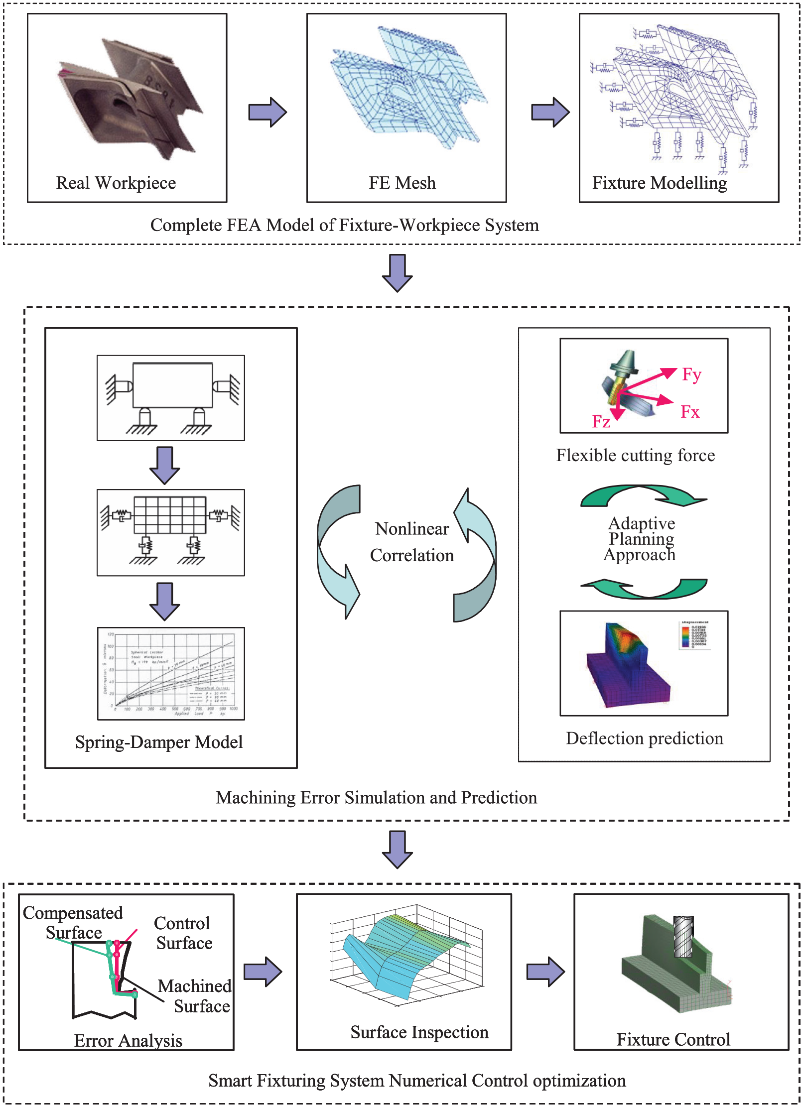
An adaptive machining planning environment methodology.
Modelling of a fixture-workpiece system
Components of the fixture (supports, actuators, clamps) can be modelled using a spring-damper system. As an example, a spring-damper model can represent an actuator in one degree of freedom as shown in Figure 2. To represent three degrees of freedom, three spring-damper models can be applied.
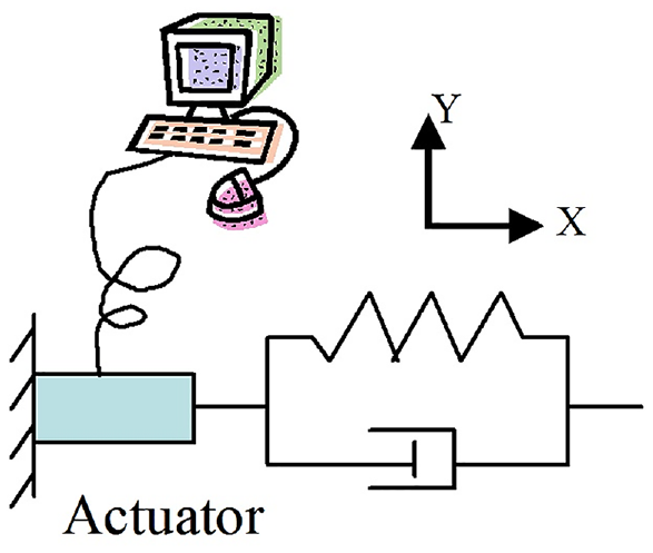
An example of a spring-damper system of an actuator.
When an actuator is compressed, it is in contact with the workpiece. In this case, the relative movement (displacement) between the workpiece and the actuator is negative and equal to the deformation caused by the compression. When the displacement becomes positive, the actuator loses contact with the workpiece and the spring does not generate a resistance. In the model, a force function F is constrained under a given upper limit Fupper (see Figure 3). To avoid relative movement (loss of contact or sliding) between the workpiece and the actuator, a lower force limit, Flower, is applied to the force function. The model for the virtual spring can be defined as a nonlinear force-displacement relationship,

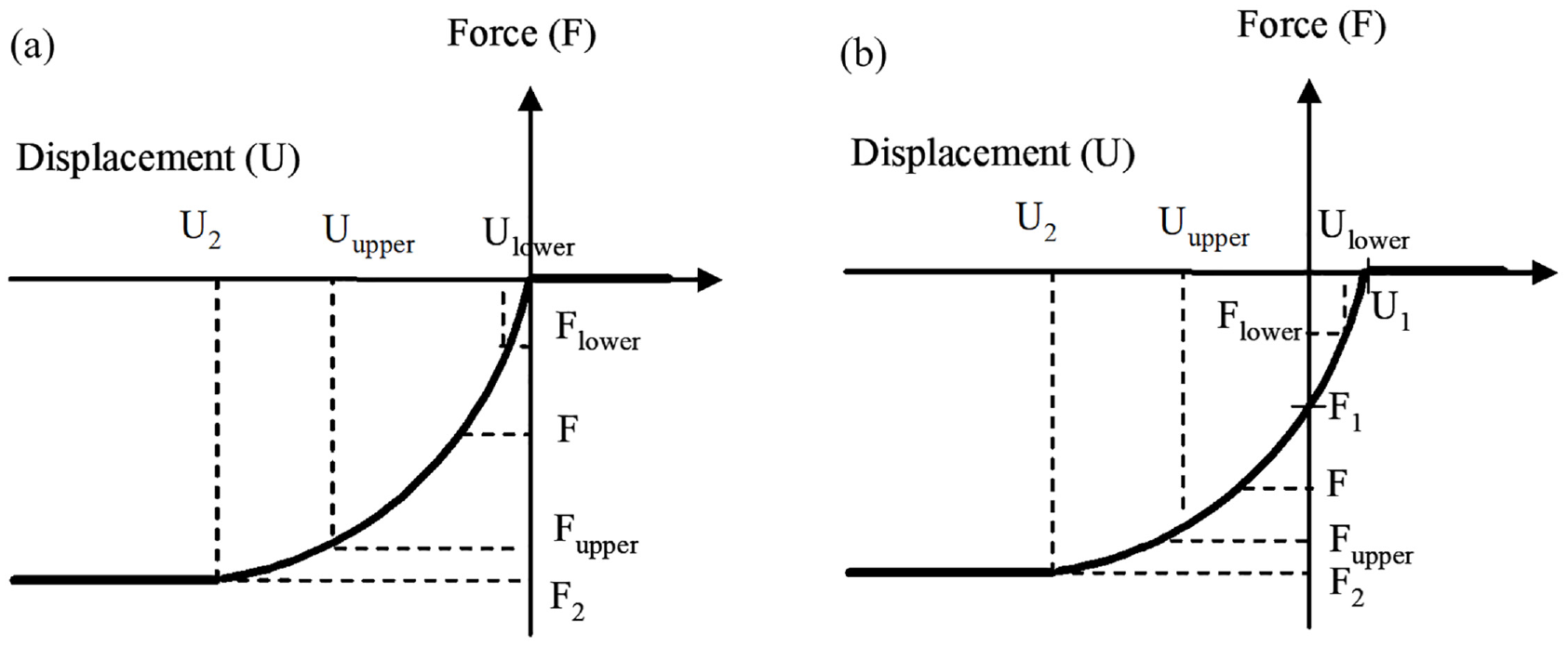
A nonlinear model for a spring,
where the force, F, is applied by

The exact data for the force-displacement relationship can be obtained using the experimental methodology developed in Ratchev et al. 30 The virtual springs can be modelled using finite element codes by applying the corresponding non-linear stiffness in tension and compression. For scenarios when the actuator loses contact with the workpiece, the spring should be modelled with zero stiffness in tension. Due to the initially applied force, the actuators are initially compressed.
Figure 4 shows a model of a thin-wall flexible slender part created in ANSYS representing a fixture-workpiece system with three actuators modelled with three spring elements. The red area represents the clamped material, while the red arrow shows the applied cutting force. The applied stiffness for the three actuators is 3 kN/mm. The Ti6Al4V slender part is modelled with a modulus of elasticity of 110 GPa and Poison ration of 0.33. Static analysed are conducted to find the relationship between applied force and deflection for a modelled fixture-workpiece arrangement. The same model without springs is used for the validation of the proposed machining error prediction approach.
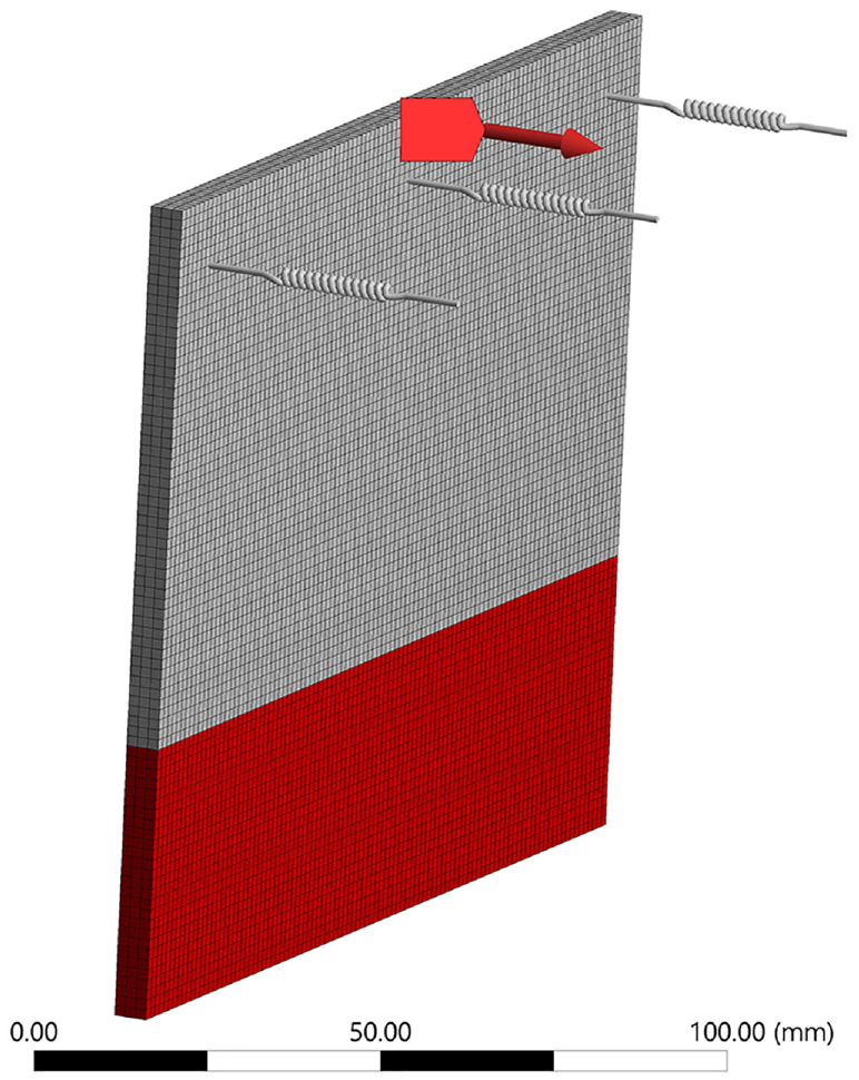
FE model of a fixture-workpiece system with three actuators modelled with springs in ANSYS.
Theoretical cutting force model in milling
In this study, a machining process of down milling is used. An infinitesimal segment of a mill cutter tooth is assumed as oblique cutter. Three force components,
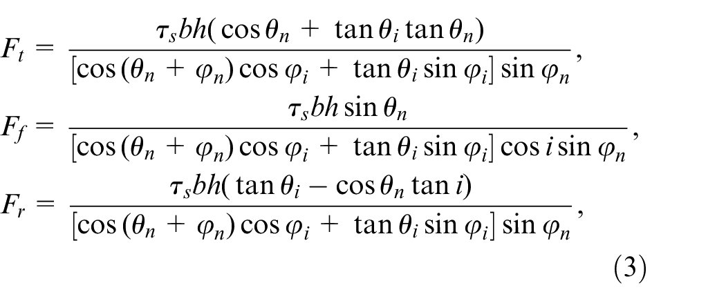
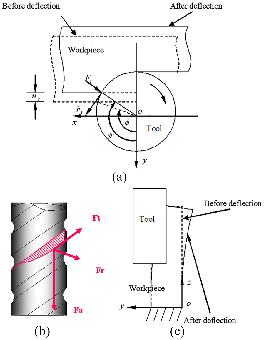
Illustration of cutting forces and workpiece deflection. (a) view along z-axis, (b) cutting edge, and (c) view along x-axis.
where

It needs to be highlighted that the shear plane model has its limitations.
32
The model does not consider the tool geometry, tool material, contact conditions over the tool-chip and tool-workpiece interfaces. It also does not represent the properties of the workpiece material including hardening, thermal and strain rate effects.
33
Despite the limitations of the shear plane model, it has been favourably used in machining applications.
32
The angles
where
Multi-step error predictive approach
The error compensation in the y-direction is chosen as an example to illustrate the general error compensation approach (see Figure 6). Figure 6(a) shows the point p on the nominal surface finish which is laying at the cutting position when the cutter is passing through the sampling point j (see Figure 6(b)). As the cutter is engaged, under the cutting force, the designed cutting position p on the workpiece deflect to the position p1 (see Figure 6(b)). As a consequence, in a machining process without error compensation, the desired point on the line ab of the workpiece deviates to a1b1 due to workpiece deflection. As the machining process is completed, the actual cutting point at the sampling point j changes to p2 as the deflected part recovers. The actual surface finish in the plane xpy on the workpiece will take positions at a2b2 after recovery of the workpiece by error of U.
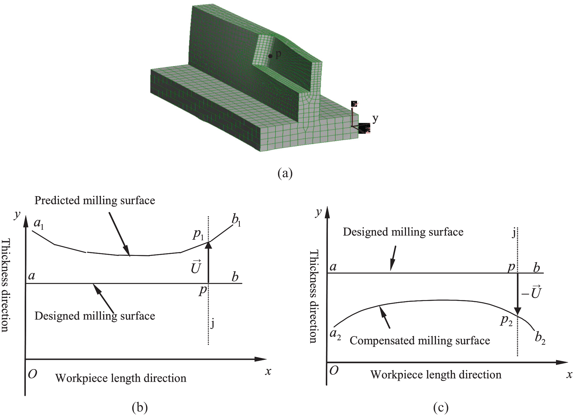
Actuator numerical control for error compensation. (a) 3-D view of cutting point p when cutter passes sampling point j, (b) 2-D down-view of the predicted error at the sampling point, and (c) 2-D down-view of the compensated error at the sampling point j.
In machining of flexible structures, the cutting force changes due to the change of the effective radial depth of cut which depends on the deflection of the part, tool and fixture response. To resolve this complex dependency, an interactive approach is employed to find the equilibrium state of the cutting force and the part deflection. A multi-step error prediction for force induced error requires sampling points along the workpiece length (see Figure 6) where the workpiece deflection (U1) is obtained from the equilibrium state of the flexible cutting force and workpiece deflection through an iterative procedure. Due to the workpiece deflection, the radial depth of cut is smaller than the planned one during the toolpath generation. Therefore, the removed material volume and the cutting force will be smaller than the calculated cutting force under the initially planned nominal radial cut of depth in the toolpath. In general, as soon as the radial depth of cut is compensated, the designed milling surface is moved further towards the tool. As a consequence, the radial depth of cut and cutting force become larger than the predicted force in the last iteration where the cutter and the workpiece will be in an equilibrium state at the different position. As the fixturing system compensated to X1 by error of U1, a new workpiece deflection (U2) can be found and so on. Using the compensated workpiece position (Xi) in which the errors are calculated in the previous iteration step i, a new deflection error value Ui + 1 is computed and the new deflected position of the designed cutting position on the workpiece is found. The newly predicted workpiece deflection error (Ui + 1) is again used for the workpiece position compensation from position Xi to Xi + 1. The difference between the successive two compensated positions is expressed as:

The tolerance for terminating the multi-level iteration and moving to the next sampling point is based on the difference of the workpiece deflection between two successive prediction steps (

The correction of the designed position

The machining error can be mitigated by applying an error compensation approach. As an example, a error compensation approach is depicted in Figure 6. Figure 6(a) shows the point p on the nominal surface finish which is laying at the cutting position when the cutter is passing through the sampling point j (see Figure 6(b)). As the cutter is engaged, under the cutting force, the designed cutting position p on the workpiece deflect to the position p1 (see Figure 6(b)). As a consequence, in a machining process without error compensation, the desired point on the line ab of the workpiece deviates to a1b1 due to workpiece deflection. As the machining process is completed, the actual cutting point at the sampling point j changes to p2 as the deflected part recovers. The actual surface finish in the plane xpy on the workpiece will take positions at a2b2 after recovery of the workpiece by error of U.
Results and validation
Five turning trials, representing orthogonal cutting, were conducted at a cutting speed of 18.85 m/min, depth of cut of 2.54 mm and a feed rate of 0.03 mm/rev (0.030 mm uncut chip thickness). The turning trials were conducted to obtain the parameters. Each of the trials was conducted on a separate Ti6Al4V rod with a diameter of 200 mm. Seco insert cutter with SCACR1616H09 holder and CCMT09T302-F2 HX inserter were attached on a CNC turning machine. The rake angle was 14°. The cutting forces in the tangential and normal cutting directions were measured with a dynamometer. The measured cutting forces in the tangential and normal cutting directions were 174.9 ± 4.5 N and 197.6 ± 3.1 N, respectively. The shear angle was obtained to be 32.4 ± 0.35°. A shear strength of 760 MPa is used for the Ti6Al4V workpiece material for the cutting force model.
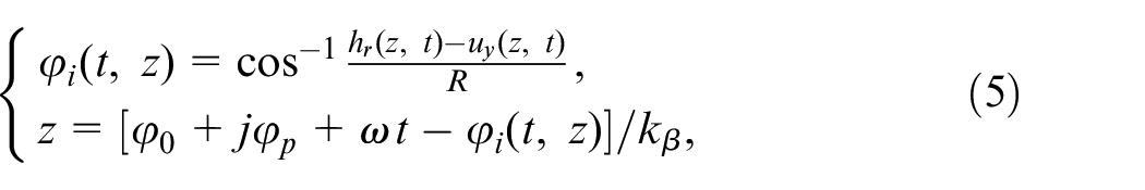
A flexible milling experiment was conducted to validate the error prediction methodology. The force components were measured with a dynamometer. The milling error on the surface finish is measured by displacement sensors on-line and inspected off-line using coordinate measurement machine. In the milling trials, the displacement sensors were fixed on the machine column perpendicular to the ideal machining surface towards the mill cutter centroid. Eight-force-component signals are sent from the dynamometer to the amplifier, a connection box and then to the data acquisition card on the computer by specific cables. The on-line displacements are detected by inductive displacement sensors that link to the connection box and then to the data acquisition card. For validation, the part is selected to be a thin-wall slender part (see Figure 2) made of Ti6Al4V alloy. The required machined profile is a flat surface. During milling, the workpiece deflection is in the y direction, which is perpendicular to the machined surface, showed the most significant machining error of the surface profile. The contributions of the workpiece deflection in the feed direction (workpiece longitudinal direction), x, and the tool axial direction, z, are negligible. Therefore, the investigation is focused only on error prediction and in the y direction.
The deflection was measured at nine equally spaced points at intervals of 15 mm along the line
The predicted and measured force components in the workpiece thickness direction, Fy, and the resultant force obtained for the thin-wall slender part without actuators are shown in Figure 7. Figure 8 shows the measured and predicted milling error. The predicted values are obtained under the same machining condition as in the corresponding experimental trials. By comparing the predicted and measured cutting forces and milling errors, it can be seen that the predictions capture the physical behaviour of the cutting forces and induced milling error. The maximum difference between the predicted and measured forces in the workpiece thickness direction (y) is less than 9%. On average, the difference at all sampling points is approximately 6%. In regard to the milling error, the average difference is less than 6%.
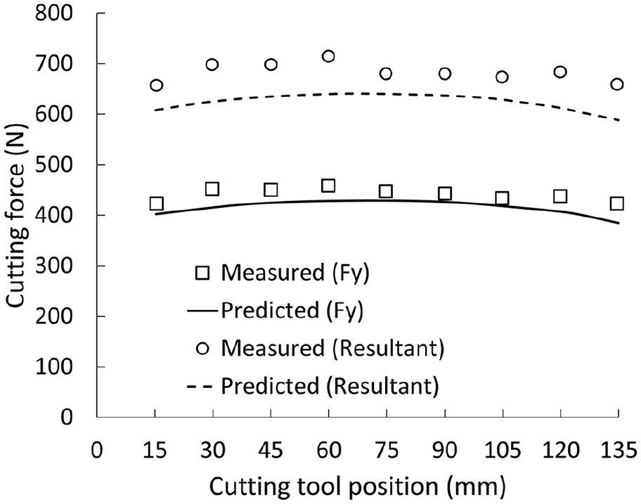
Comparison of the measured and predicted forces (no fixture).
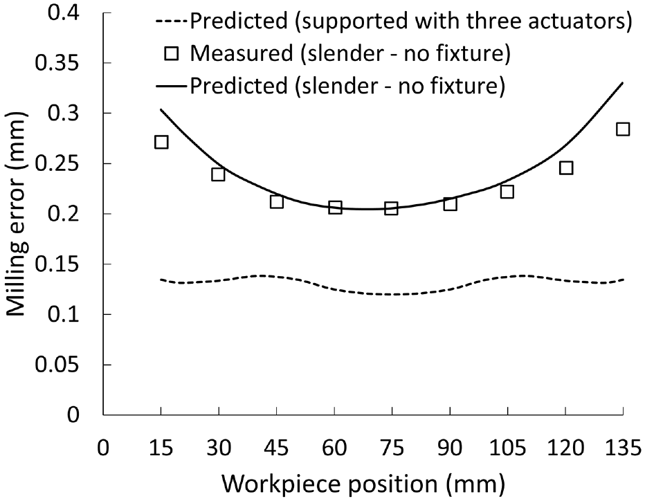
Comparison of the measured and predicted milling error in the thickness direction.
Figure 8 also shows the predicted milling error for a fixture modelled with three actuators (see Figure 4). It can be seen that the milling error is reduced, and it is in the range of 0.12–0.14 mm. It can be also seen that the milling error is more uniform across the machined surface. Both factors, reducing the milling error in magnitude and producing more uniform error distribution across the machined surface, can lead to more successful mitigation of the machining error using compensation.
Conclusions
This paper presents a finite element based milling error prediction methodology for enabling the simulation of a fixture-workpiece behaviour in milling of a low rigidity Ti6Al4V slender part. The methodology was fostered by an advanced theoretical cutting force model and a multi-level error prediction approach. The following key findings were derived from this research work:
The results of the experimental validation of a low rigidity Ti6Al4V slender part showed an average difference between predicted and measured cutting forces at nine sampling points of approximately 6%.
The predicted and measured milling errors were compared, and the average difference at nine sampling points was found to be less than 6%.
The low rigidity Ti6Al4V slender supported with three modelled actuators showed more uniform distribution of the predicted milling error. Also, the milling error reduced from the range of 0.2–0.33 mm (no actuators) to the range of 0.12–0.14 mm (with actuators).
The results from the simulations and experiments demonstrated that the proposed methodology is capable of predicting the milling error with desirable accuracy providing the confidence that the methodology can be used in the design workflows for development of smart fixturing systems. The proposed methodology has the potential to be used for process monitoring and control through the use of controllable actuators to further mitigate machining errors as well as mitigation of vibrations by considering the dynamics of the milling process. These would require further investigation in a near future research.
Footnotes
Declaration of conflicting interests
The author(s) declared no potential conflicts of interest with respect to the research, authorship, and/or publication of this article.
Funding
The author(s) disclosed receipt of the following financial support for the research, authorship, and/or publication of this article: Authors wish to acknowledge the financial support from the UK Engineering and Physical Science Research Council (grants: GR/R13098/01 and EP/E001904/1) and the European Commission (VERDI project: grant agreement 516046).